Creating 3D Isometric view of various structural elements in AutoCAD
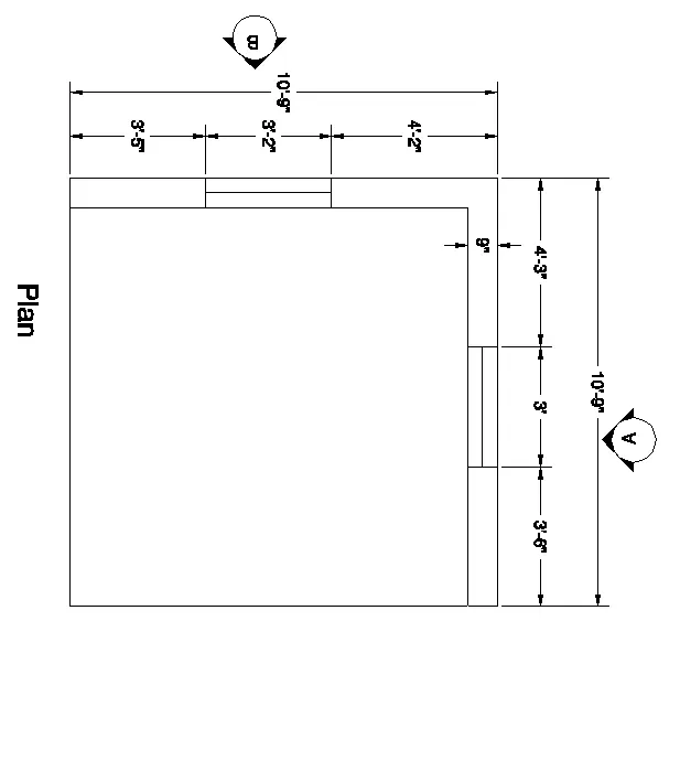
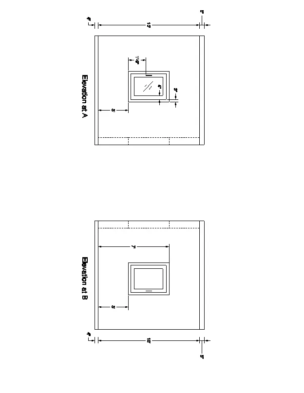
1. Create a 3D Isometric View of the building with plan and elevation given.
Aim:
To create a 3D Isometric View of the building with plan and elevation given using the AutoCAD software
Introduction:
Create a 3D Isometric View of the building with plan and elevation given
Procedure:
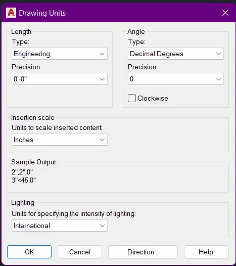
- First of all open after open the software, type UN for units command
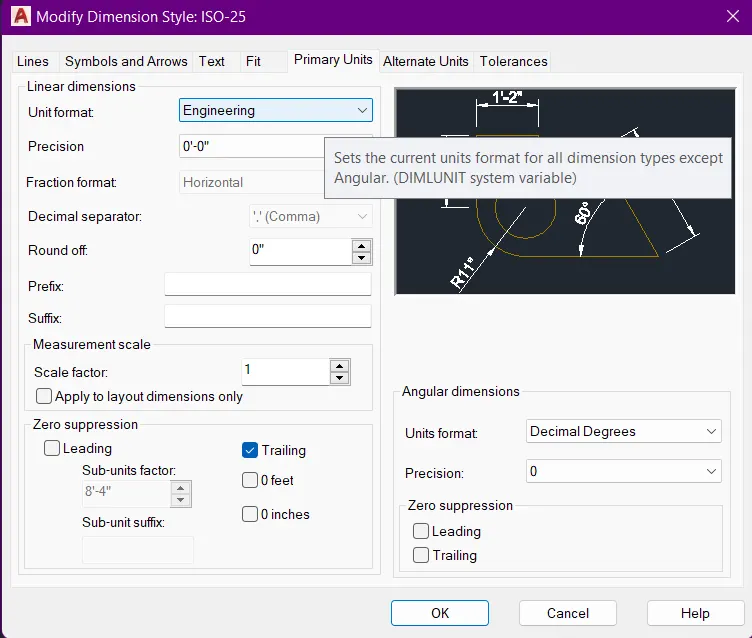
- And then select the length type is Engineering, precision is 0'-0" and finally select the insertion scale is Inches
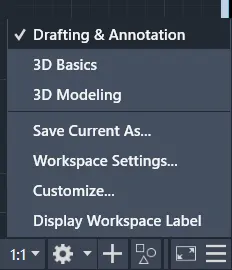
- This drawing starts with the Drafting & Annotation window of workspace
- Then give a Dimension style is which type i want to give this drawing
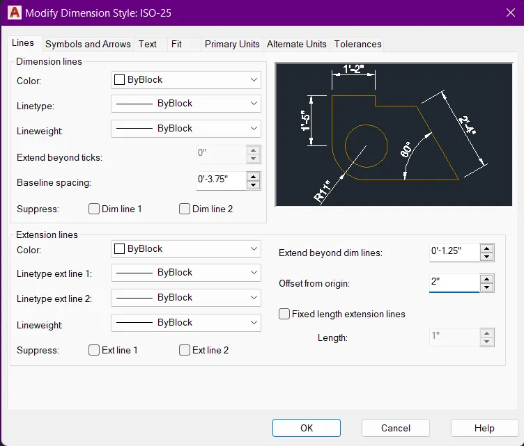
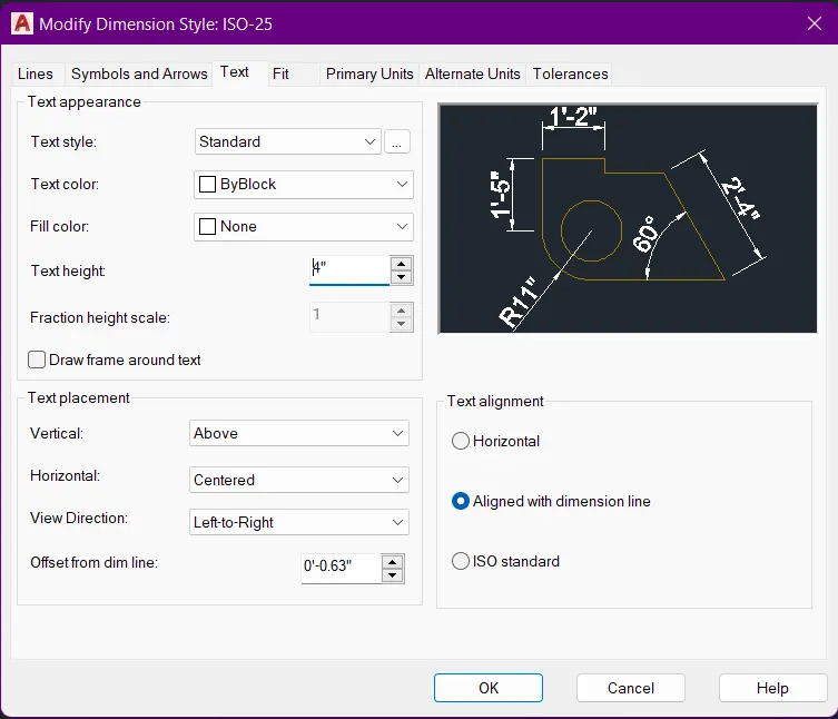
- Type Dimstyle command and select Modify button
- Then give a values of Line, Text and Primary units
- The Primary Units is Engineering, precision is 0'-0" and finally select the insertion scale is Inches
- In the Line tab give the Offset from the line is 2"
- In the Text box give the text height is 4"
- Next start to draw the plan of the building as given in the question
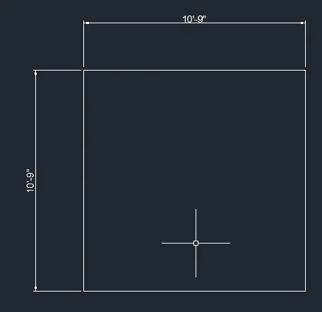
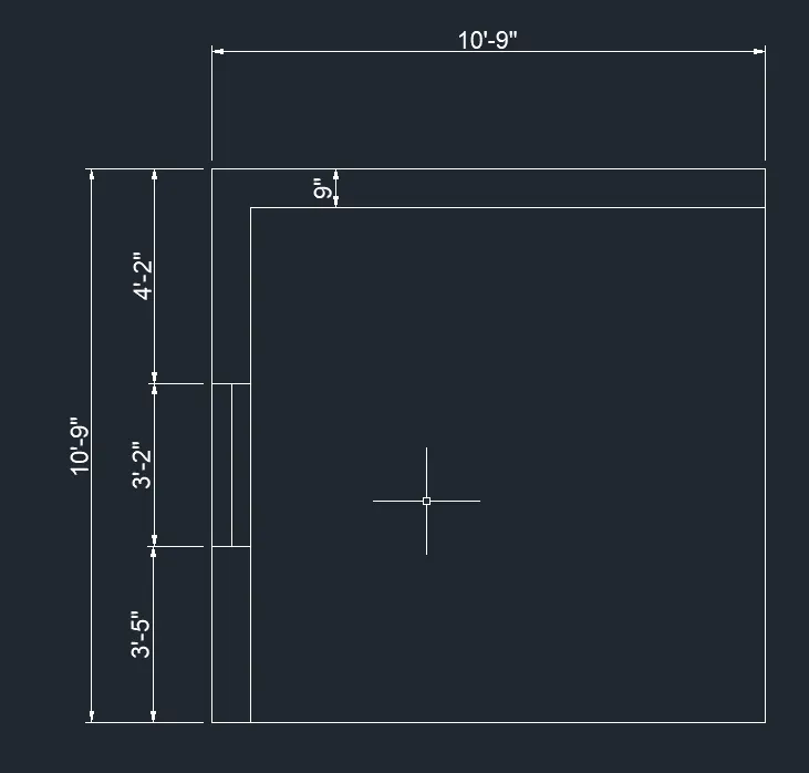
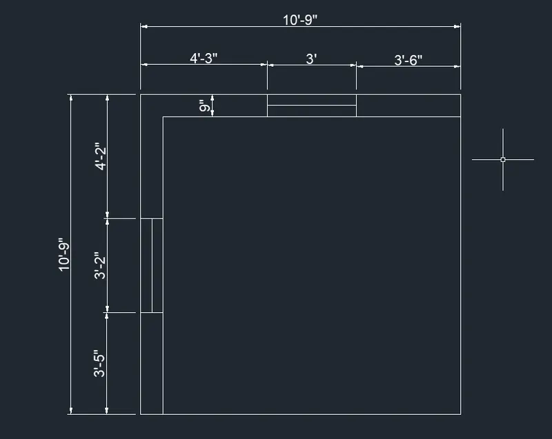
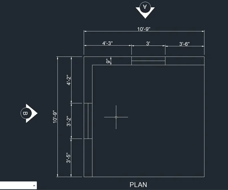
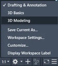
- Then use the 3D Modeling workspace for create the 3D view of the sketch
- And create a boundary for the extrusion of the walls
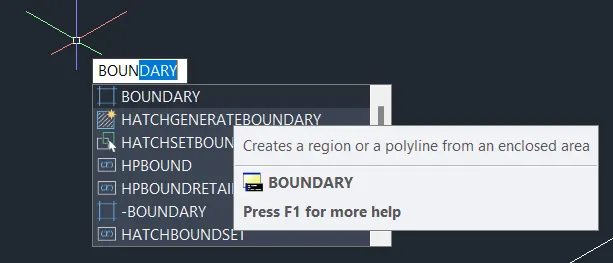
- Here, type the Boundary command and select the wall areas and create the boundary
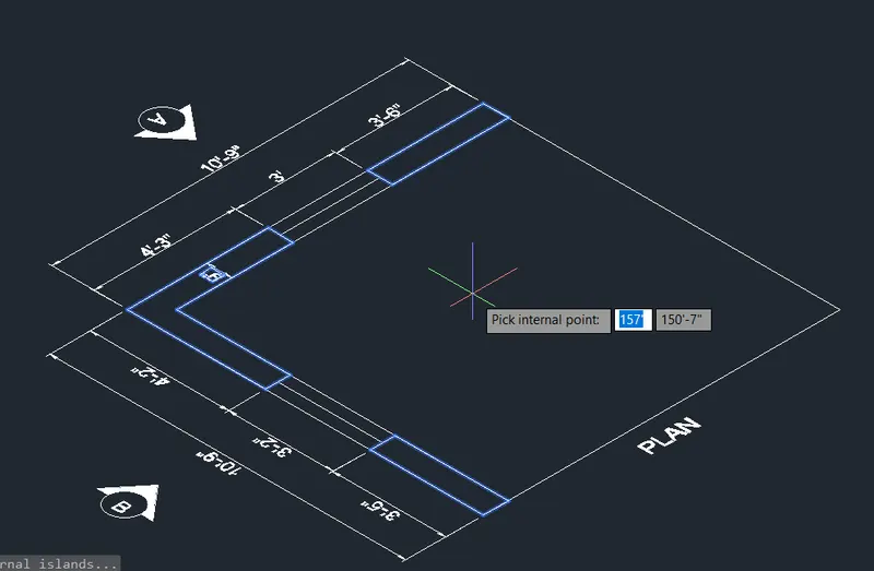
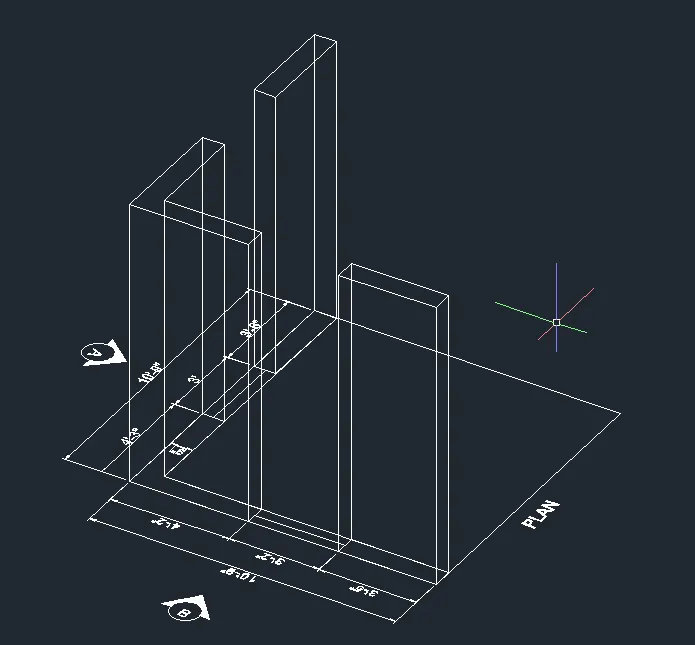
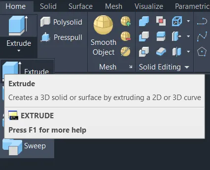
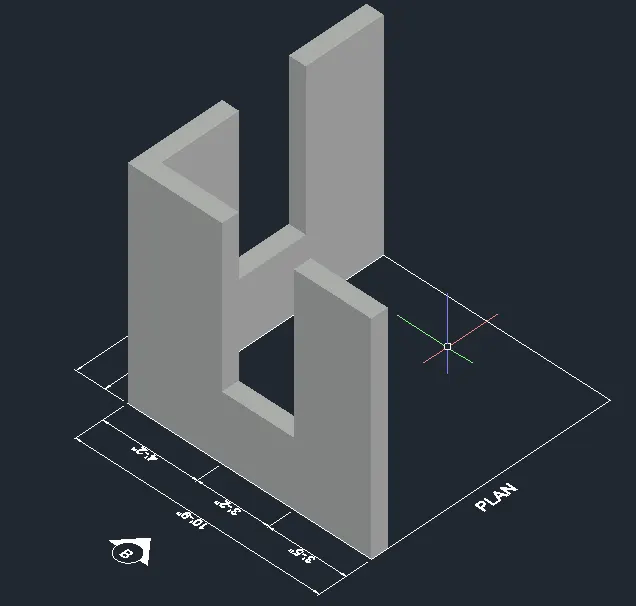
- And create the wall by using the Extrude command the height of 10'
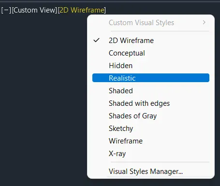
- Then go to Realisitic for see the 3D view of the walls
- The boundary is created by this process
- After type the boundary command the dialogue box will open as shown in below figure
- Select the Pick Point and select the areas and click OK

- Here, using the UCS command for select the Axis of the drawing
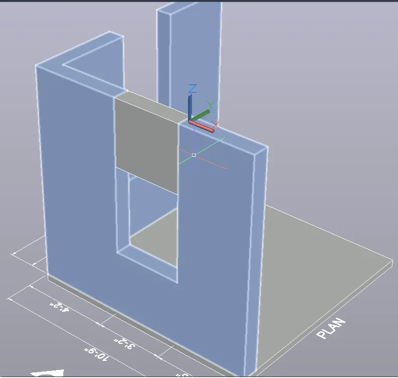
- Click Face option to create the Rectangle using the REC command
- And refer the height of the window then Extrude the rectangle for the Window
- For the both side walls
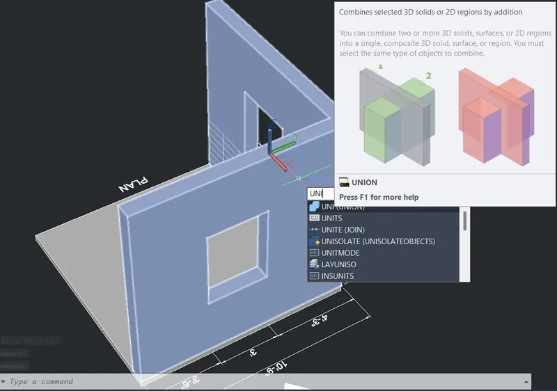
- Then using the Union command for create the model in one object
- Type the Union command and select the all extruded objects and then click Enter button
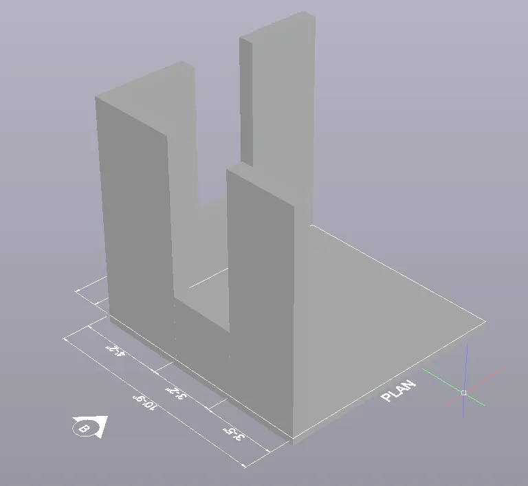
- Here, create the floor area in the wall bottom side by using the Boundary and Extrude commands
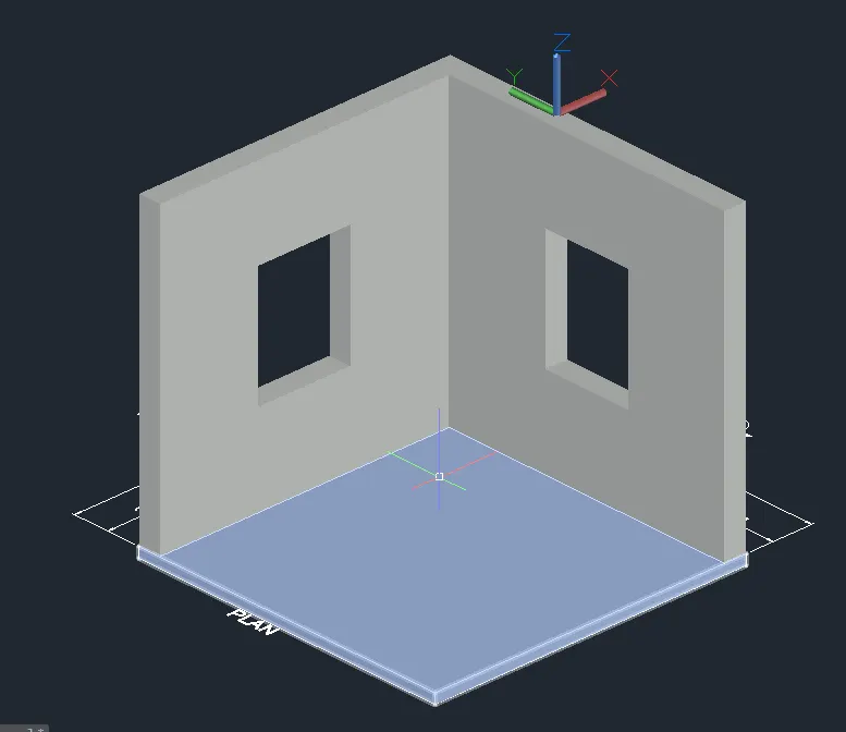
- And then create a window in both side walls as given in the Elevation drawings
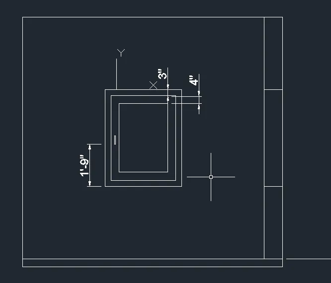
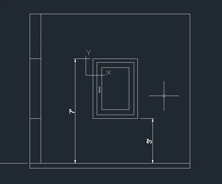
- The size of the window is also refer that drawing
- Here using the REC command and Offset the rectangle in two times 3" & 4"
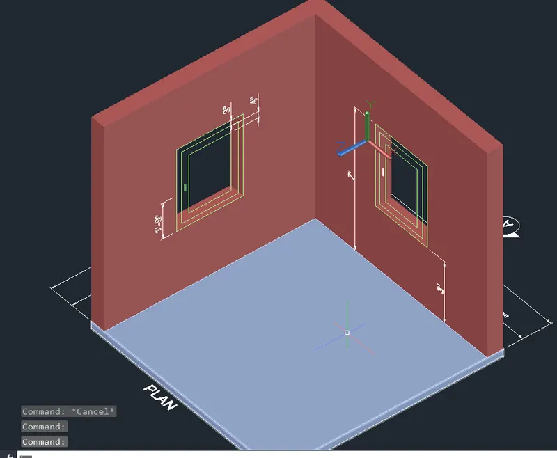
- THe window is drawn as shown below figures
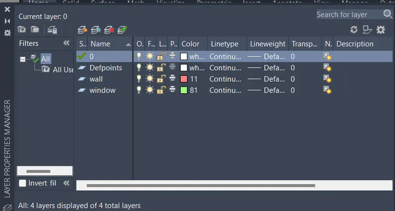
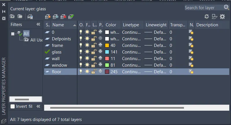
- Creating the Layer properties for Walls, Windows frames and glasses
- The Layer properties are taken in as shown in below figure
- Give the name and color of the layer is as i want
- And select the walls and give the layer to that walls
- Then select the window lines and give the window frames layers
- And Extrude the window frames in 5" and creating the Glass frames in 3" and the glass is 1"
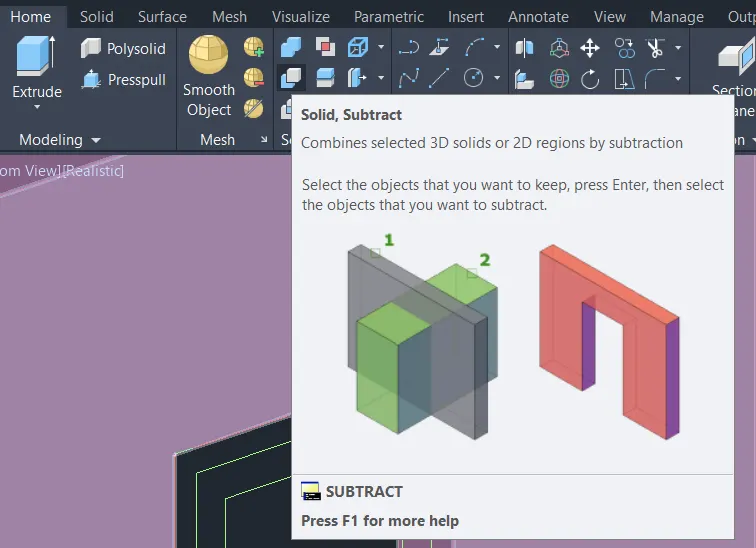
- Finally create the window using the Extrude and the Subtract commands
- And finish the 3D model drawing by using the all commands as shown in above steps
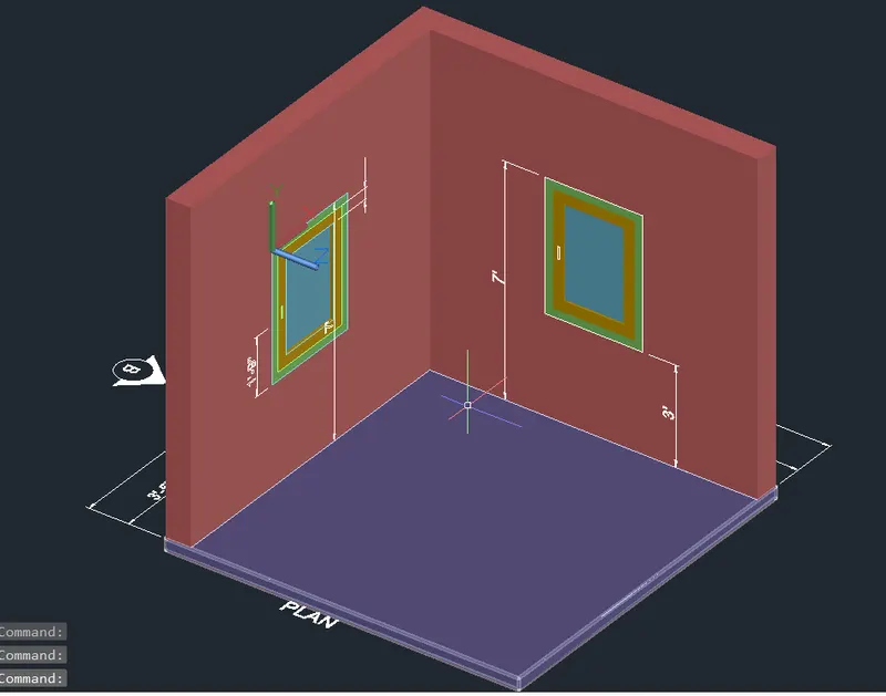
- Take the screenshots by using the Snipping tool
- The shortcut of the snipping tool is Windows key+Shift+S
- The screenshots are taken in each steps are completed as i want to take
- Finally upload the figures to the given question
Result:
The creation of the 3D Isometric View of the building with plan and elevation given using the AutoCAD software is created successfully
2. Create the 3D View of the Building Façade as given in the plan and elevation. Also, see the detail of the window.
Aim:
To create the 3D View of the Building Façade as given in the plan and elevation by using the AutoCAD software
Introduction:
Create the 3D View of the Building Façade as given in the plan and elevation. Also, see the detail of the window
Procedure:
- First of all open after open the software, type UN for units command
- And then select the length type is Engineering, precision is 0'-0" and finally select the insertion scale is Inches
- This drawing starts with the Drafting & Annotation window of workspace
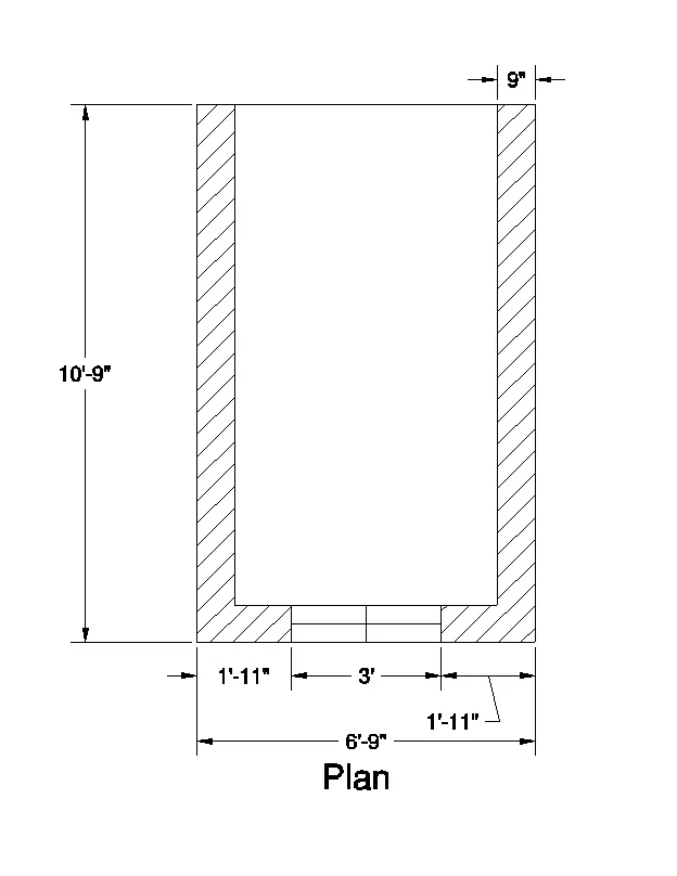
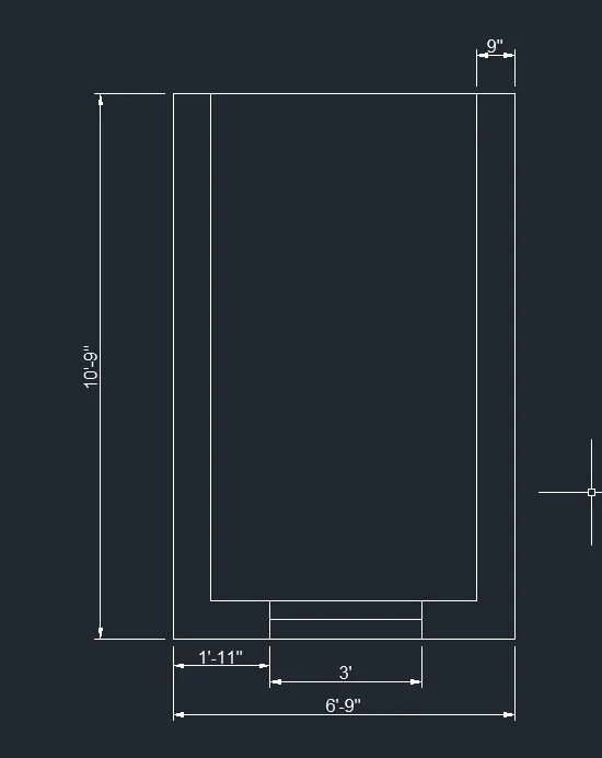
- Draw the Plan of the model drawing using the Line and Offset command
- Measure the dimension using the Dimlinear command
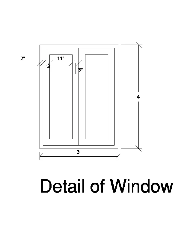
- Draw the window as using the details of window drawing in the question
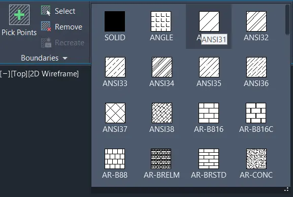
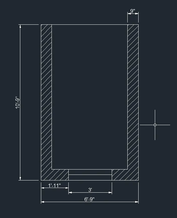
- Then Hatch the all around walls using the Hatch command
- The Hatch name ANSI31, This hatch represents the wall
- The Hatch is like as shown in below drawing
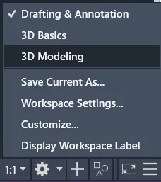
- And move to 3D Modeling worksapce for create the 3D view of the Plan
- Then create the Layer properties for the Walls, windows and annotation
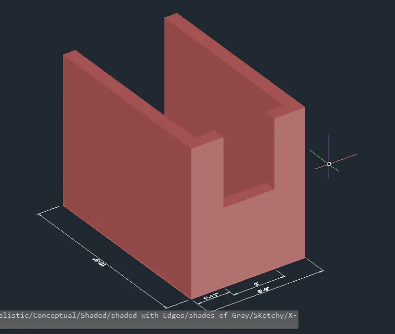
- The window is drawn with reference of the window details drawing
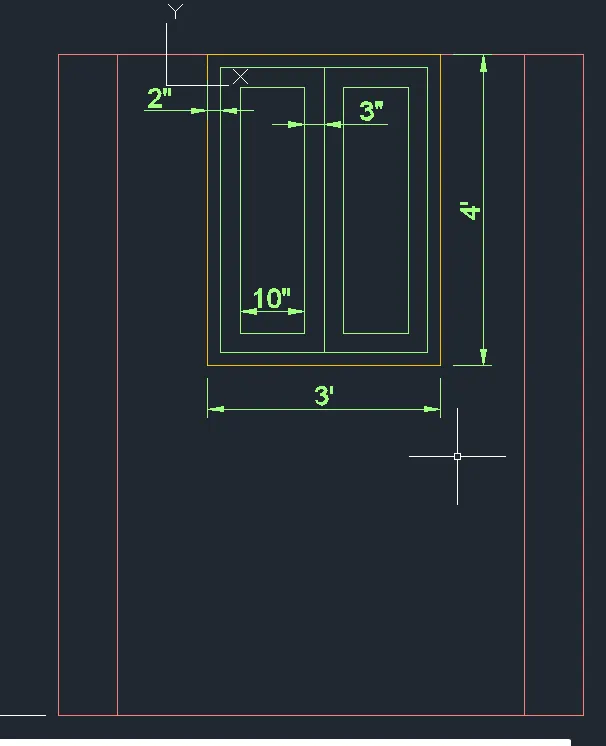
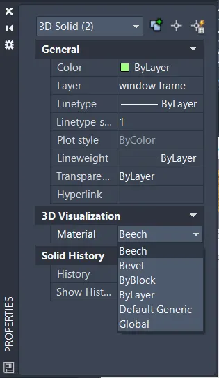
- Here, I have given the Mateials for windows by using the Material Browser tool in Visualize tab
- The procedure of the material insert to the object is given below figures
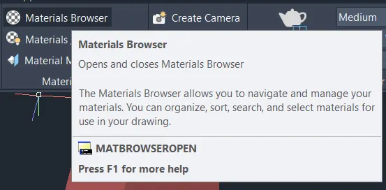
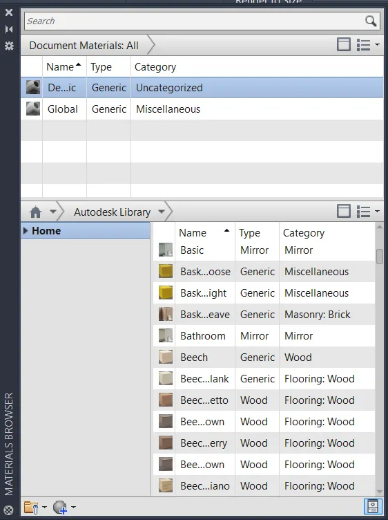
- Here, click the Add new material option and select the material i want
- And click the Add to document & edit button
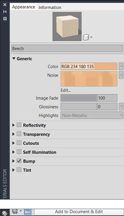
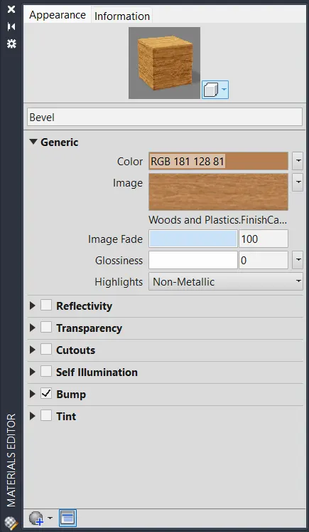
- Then right click the object which one i have to give the material
- And select Properties option and select the Material
- Then select the Material what i insert in the material library
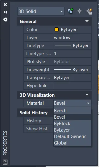
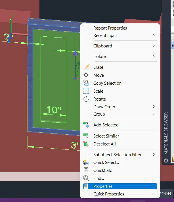
- Here, the window is as shown in below figure
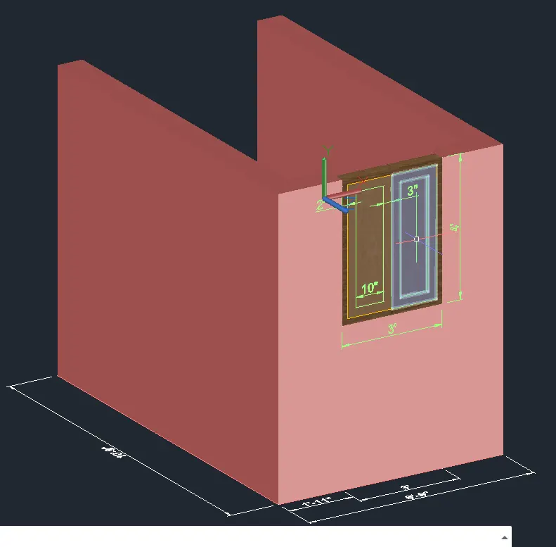
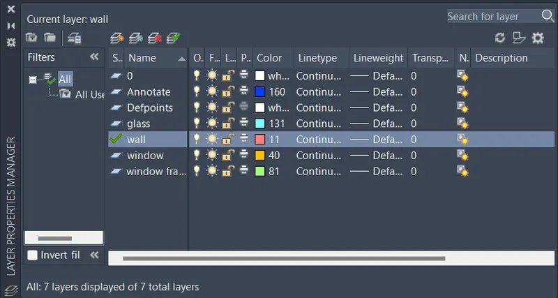
- And then create a plane lines using Line command for Extrude the wall
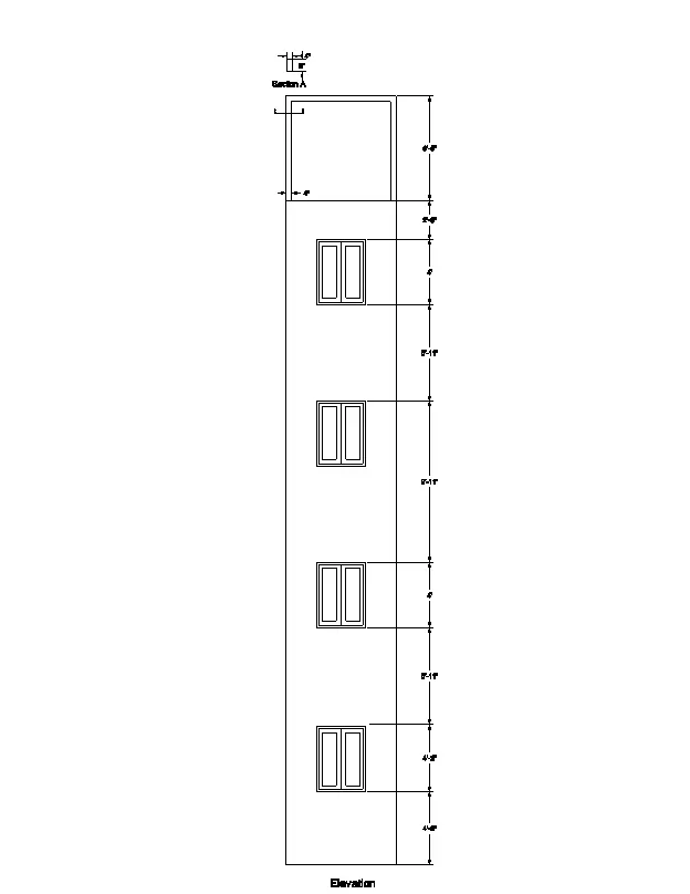
- Copy the window to next level of the building using the Copy command
- Then Extrude the wall using the Extrude command in Home tab
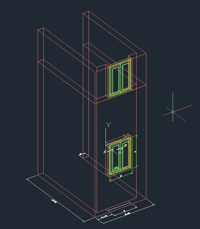
- This progress is continue until finishing the upper level of the building
- And create the roof by assuming
- At last create the extrusion work in the top of the building by using the UCS command
- And select the Face option and select the face of the building
- Then ceate a elevation of the extra work like rotated channel section using the Line command
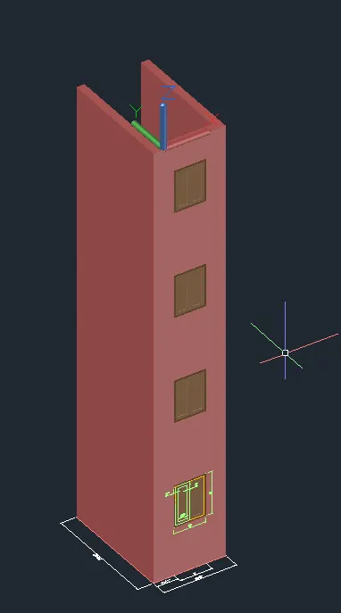
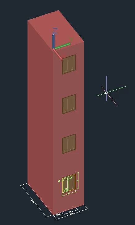
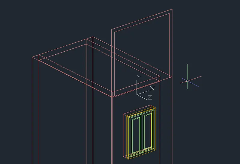
- Extrude the line the distance of 9" from the edge of the building
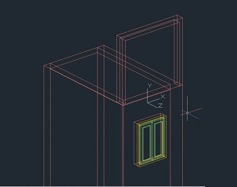
- Then see the Realistic view of the drawing
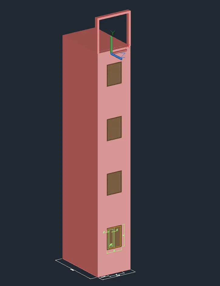
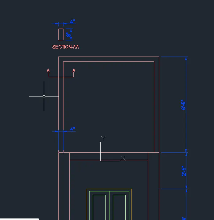
- Finally take the dimension using the Dimlinear command
- Give the layer for the dimensions
- Take the screenshots by using the Snipping tool
- The shortcut of the snipping tool is Windows key+Shift+S
- The screenshots are taken in each steps are completed as i want to take
- Finally upload the figures to the given question
Result:
The creation the 3D View of the Building Façade as given in the plan and elevation and refer the window details drawing is drawn using the AutoCAD software successfully
3. Create the ismoteric 3d view of a stair with railing as shown in the plan and elevation. Assume the size of the balustrades and the hand rails.
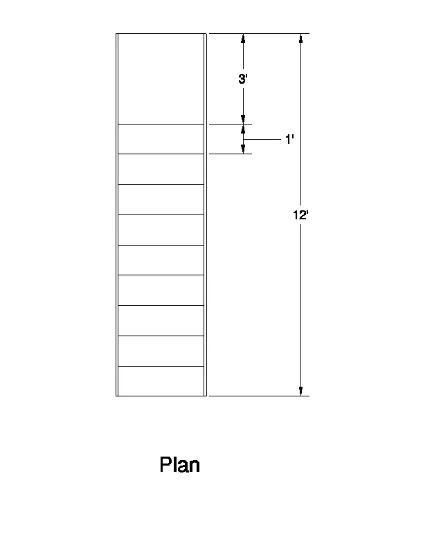
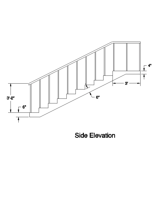
Aim:
To create the ismoteric 3d view of a stair with railing as shown in the plan and elevation using the AutoCAD software
Introduction:
Create the ismoteric 3d view of a stair with railing as shown in the plan and elevation. Assume the size of the balustrades and the hand rails
Procedure:
- First of all open after open the software, type UN for units command
- And then select the length type is Engineering, precision is 0'-0" and finally select the insertion scale is Inches
- This drawing starts with the Drafting & Annotation window of workspace
- First draw the stair paln using the Line command as given in the question and take the dimension using the Dimlinear coammand
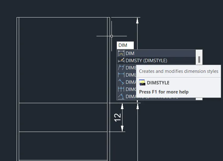
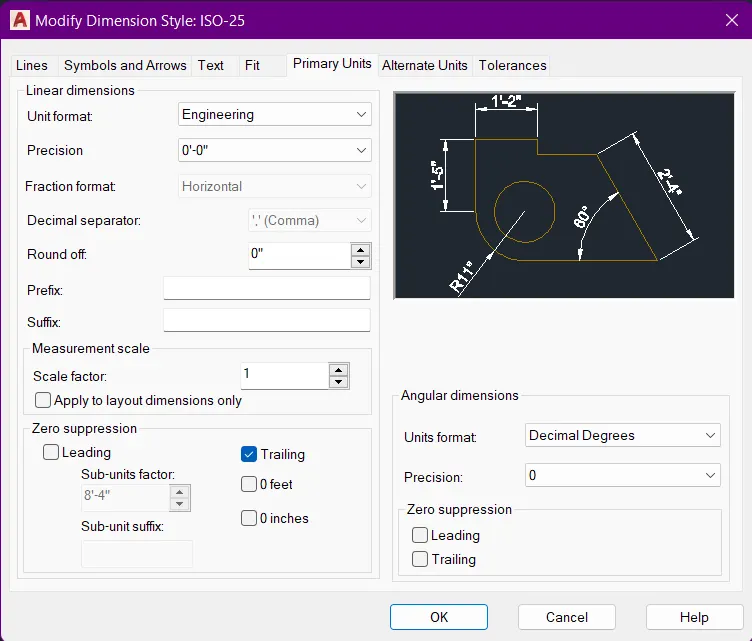
- And edit the Primary units and Lines in Dimstyle command
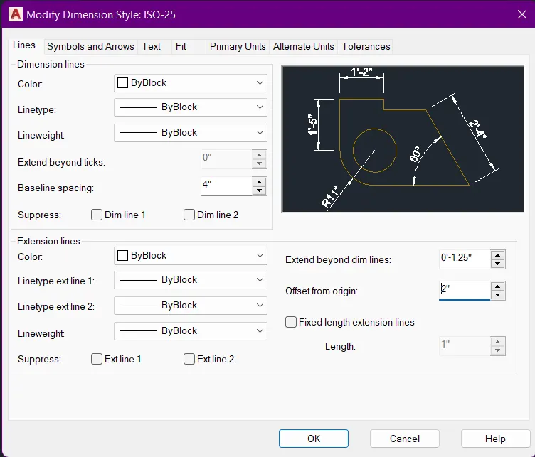
- Then give a values of Line and Primary units
- The Primary Units is Engineering, precision is 0'-0" and finally select the insertion scale is Inches
- In the Line tab give the Offset from the line is 2"
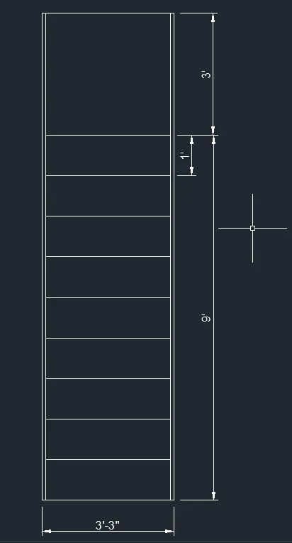
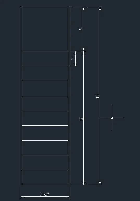
- Then draw the side elevation of the stair by using the Line command
- And the railing also using the Line command the height of 3'-2"
- Take the dimension using the Dimlinear command
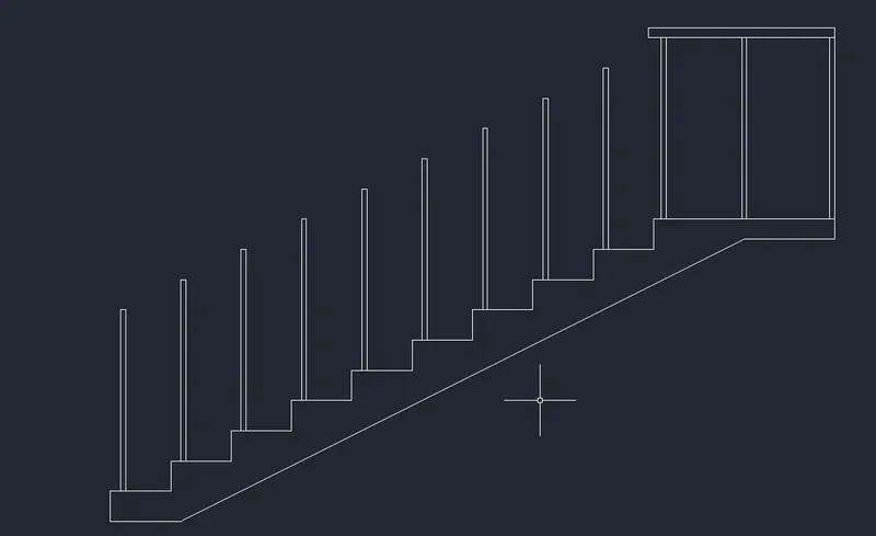
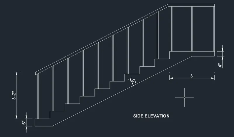
- And move to 3D Modeling workspace for create the 3D model of the stair with railing
- Change the View of the side elevation drawing
- This view is 3D rotate the side elevation drawing
- And using the Boundary command for create a boundary
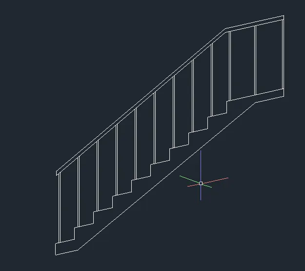
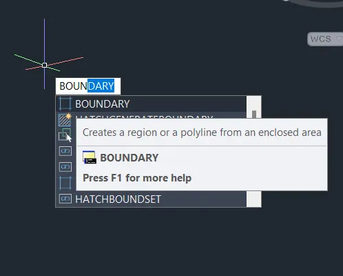
- Here, select the boundary and extrude the stair by using of Extrude command in Home menu bar
- And create the railing using the Boundary and Extrude command
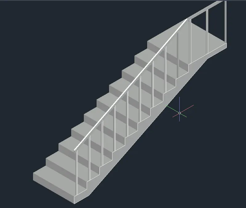
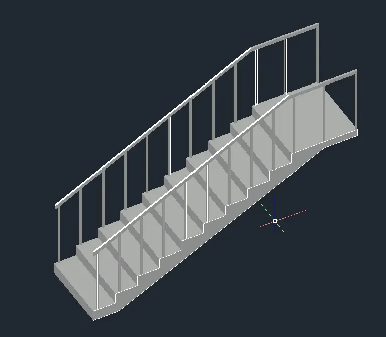
- Then copy the railings to the another side of the stair using the Copy command
- The 3D view of the stair is as shown in below figure
- And finish the model of the staircase
- Take the screenshots by using the Snipping tool
- The shortcut of the snipping tool is Windows key+Shift+S
- The screenshots are taken in each steps are completed as i want to take
- Finally upload the figures to the given question
Result:
The creation of ismoteric 3d view of a stair with railing as shown in the plan and elevation using the AutoCAD software is created successfully
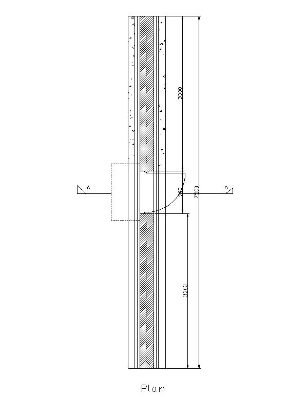
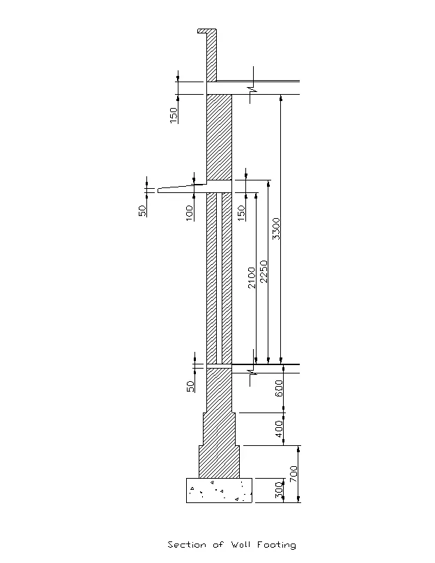
4. Create the 3D view of a Wall with spread footing . Create the Door opening only. Assume the size of the parpaet and the coping. See the plans and elevation for the details. Also, create a rendered view of the model with materials as of your choice.
Aim:
To create the 3D view of a Wall with spread footing using AutoCAD software
Introduction:
Create the 3D view of a Wall with spread footing . Create the Door opening only. Assume the size of the parpaet and the coping. See the plans and elevation for the details. Also, create a rendered view of the model with materials as of your choice
Procedure:
- First of all open after open the software, type UN for units command
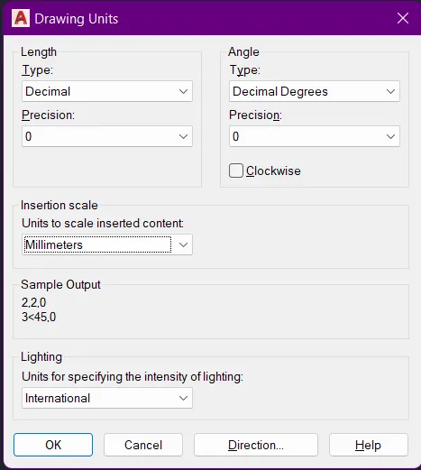
- And then select the length type is Decimal, precision is 0 and finally select the insertion scale is Millimeter
- This drawing starts with the Drafting & Annotation window of workspace
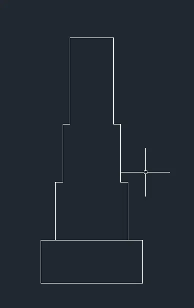
- First create the spread footing using the Line command in as given sizes
- And draw the cross section of the footing to parapet wall with refer the dimension given in the question
- The wall thickness is 300mm
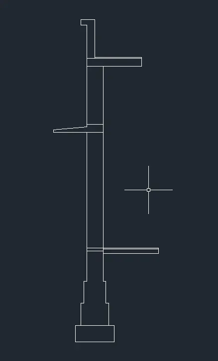
- Then move to 3D Modeling workspace
- Rotate the section drawing with help of 3D rotate option and set boundaries
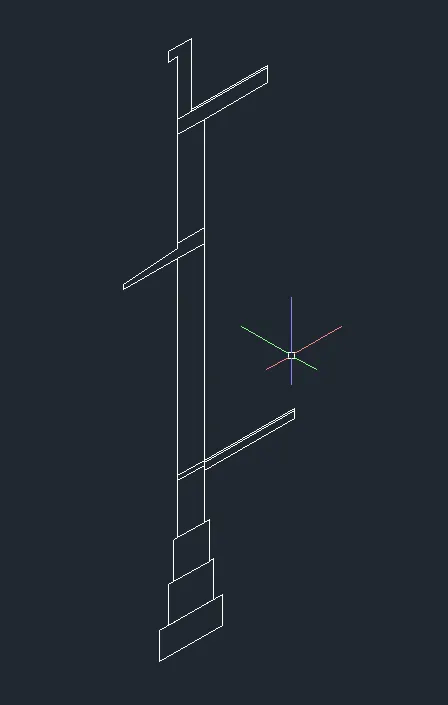
- Here, using REC command to create boundries of the each section of the building
- The boundaries are created by using the Boundary command
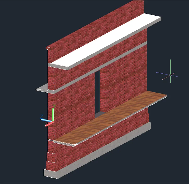
- And use the Extrude command in the length of the drawing is 7500mm as in the question
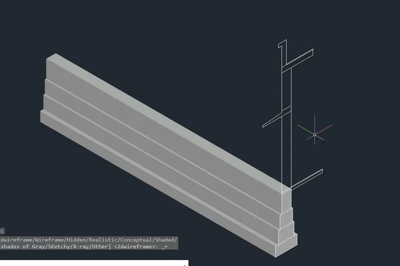
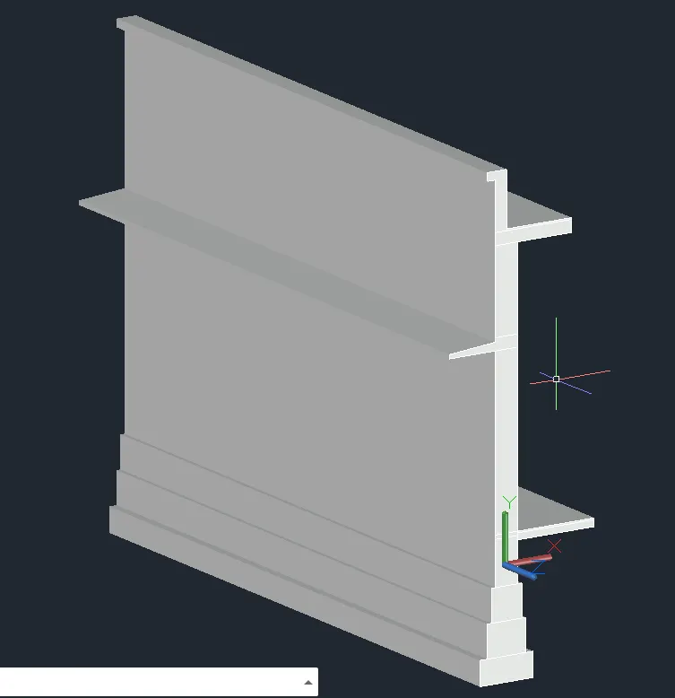
- Create the Rectangle for door in given spacing from the edge of the building
- And create boundary of the door and create a box in the door size
- Here, using the Subtract command for opening in the wall area
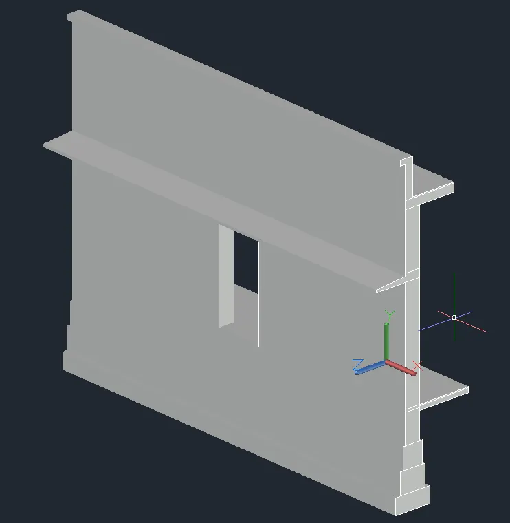
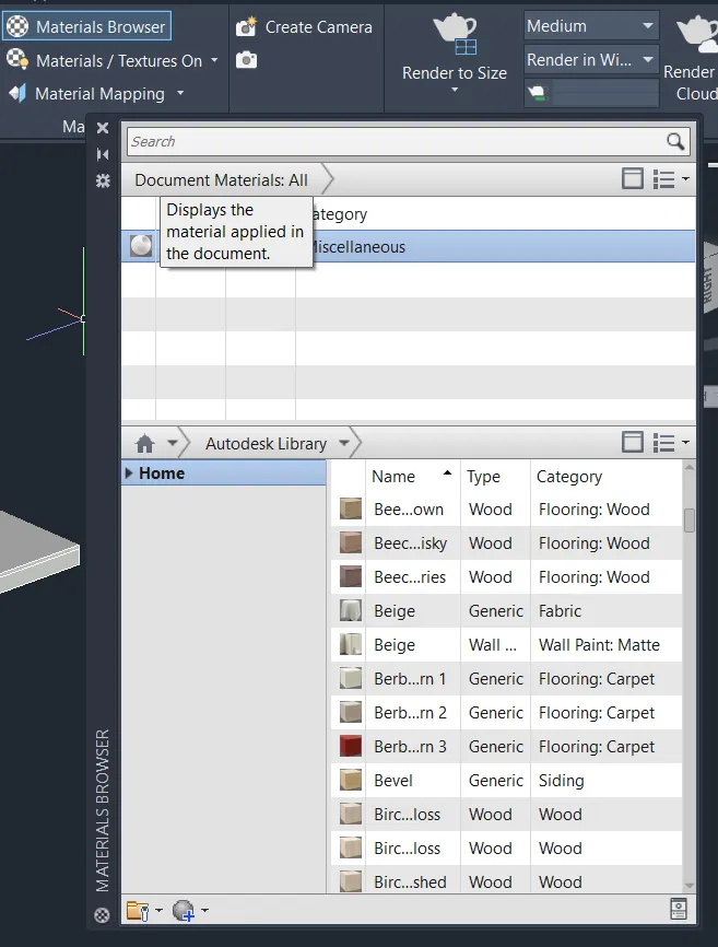
- Then give a material to the building created sections
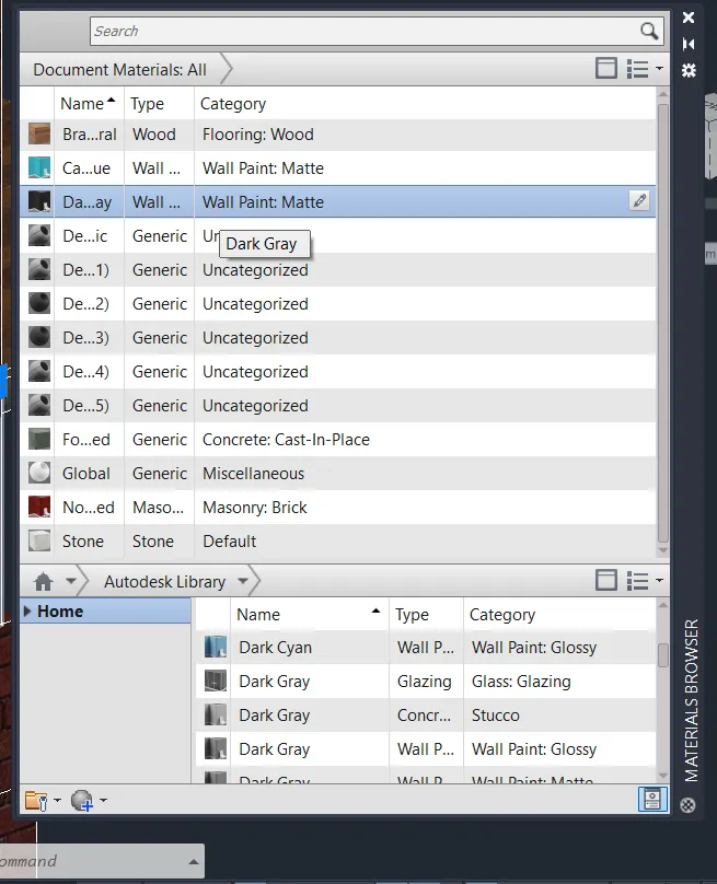
- Using Material Browser option in visualize tab
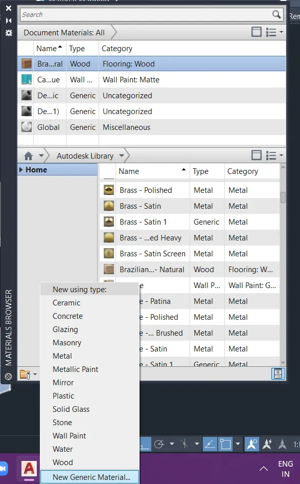
- Here, click the Add new material option and select the material i want
- And click the Add to document & edit button
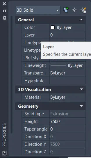
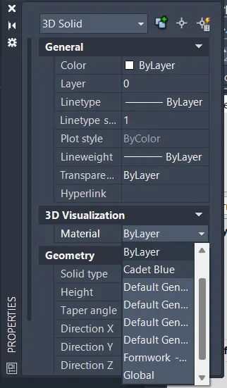
- Then right click the object which one i have to give the material
- And select Properties option and select the Material
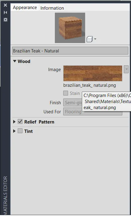
- Then select the Material what i insert in the material library
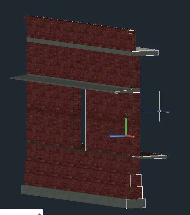
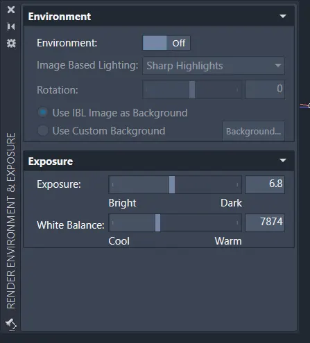
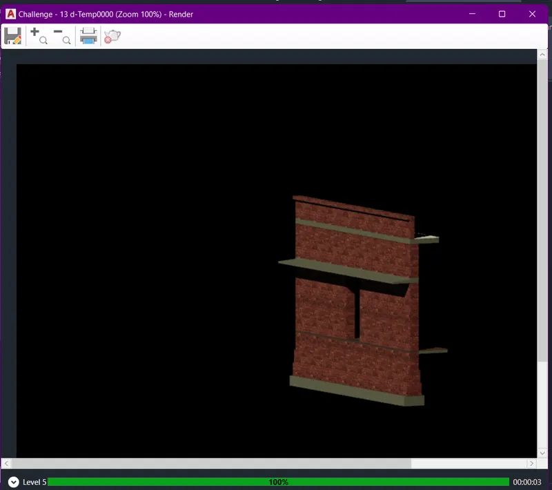
- Render the model using the RR command and adjust the brightness and clarity
- And click Render option
- Then it will finish in a second
- Take the screenshots by using the Snipping tool
- The shortcut of the snipping tool is Windows key+Shift+S
- The screenshots are taken in each steps are completed as i want to take
- Finally upload the figures to the given question
Result:
The creation of the 3D view of a Wall with spread footing using AutoCAD software is created successfully