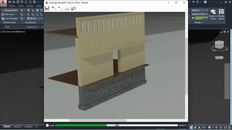
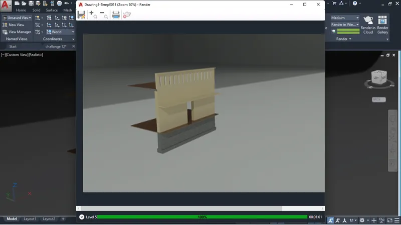
Creating 3D Isometric view of various structural elements in AutoCAD
Aim: Create a 3D Isometric View of the building with plan and elevation given.
- I am using imperial template
- Set unit to Engineering by command-UN
- now we have to go to 3d modeling how do we do that
- We can go to workspace setting and change into 3d basic or 3d modeling or we can use command- WSCURRENT to change into 3d modeling
- now go top view draw rectangle (10'9"X10'9") by command-REC
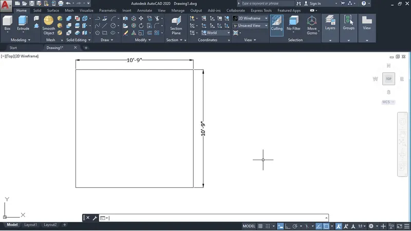
- now take offset of 9" for wall
- make window according to size
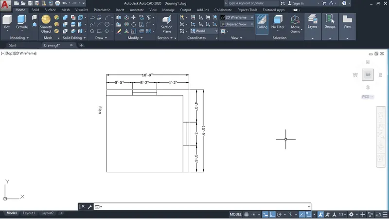
- used the construction line for elevation by command-XL
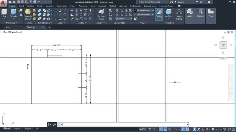
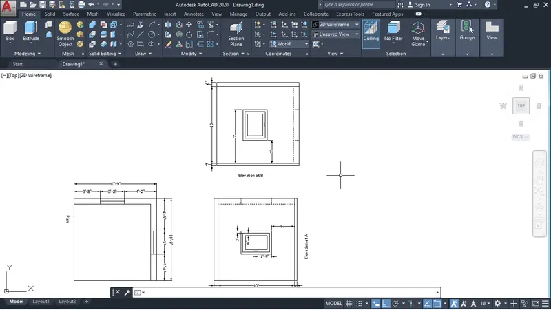
- After making elevation go to default view
- make region by command-BO or REG
- Extrude it at height 10' by command-EXT
- Extrude the window from bottom at height 3'
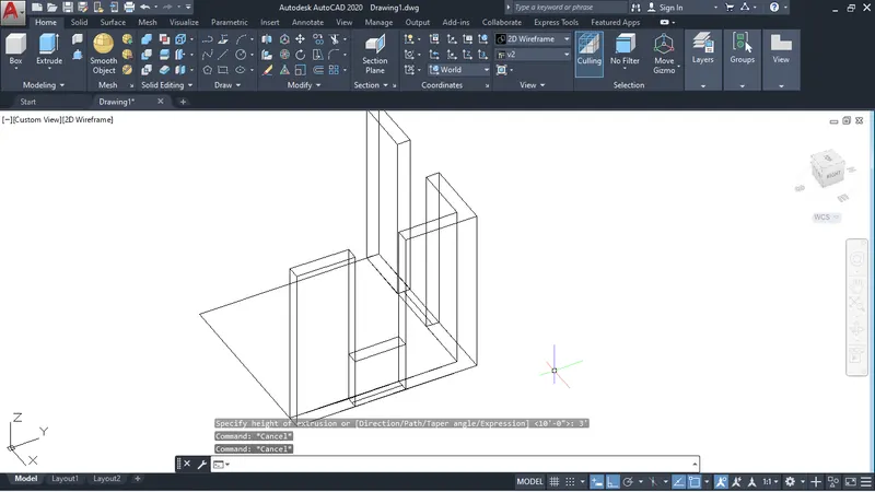
- use 3DORBIT command to see other side of the wall
- draw rectangle at bottom where window space is left
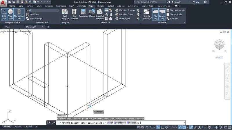
- extrude at height of 3' by command-EXT
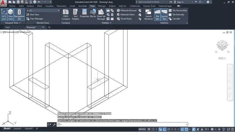
- now make the rectangle at top as you see below fig.
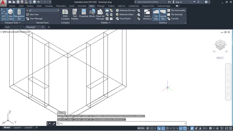
- Extrude that rectangle z-axis at height -3'
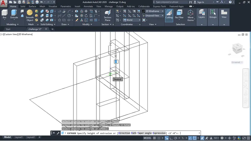
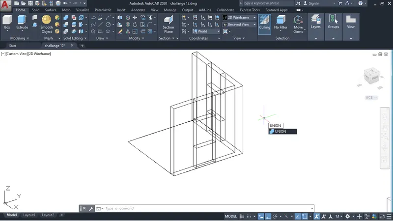
- after that make union by command-UNI
- select the object which you want to union and press enter
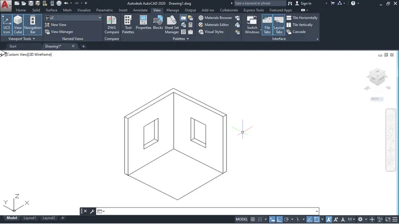
- make the copy window from the elevation
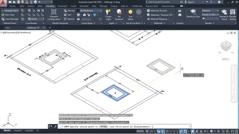
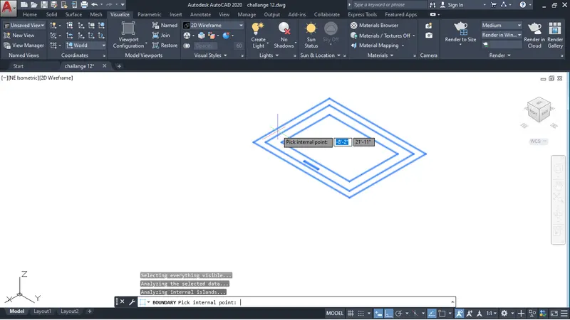
- make the region of window by command-BO
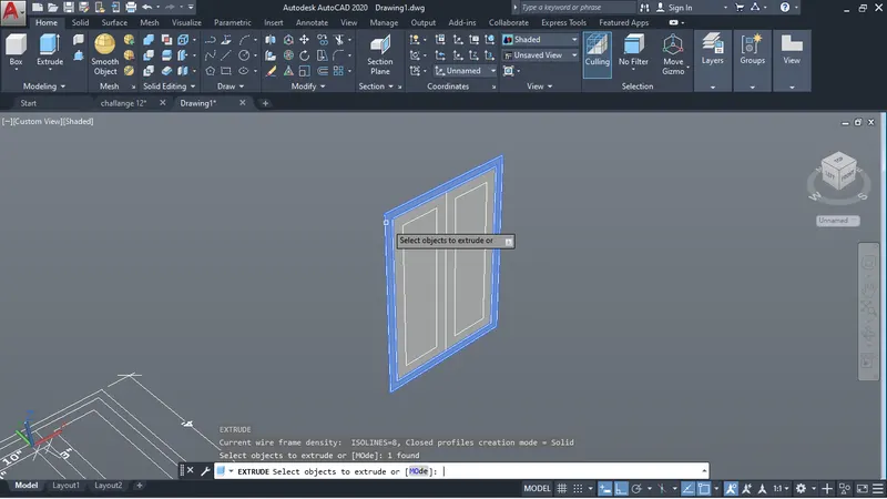
- After making region it going to look like as below fig. if you into shaded view
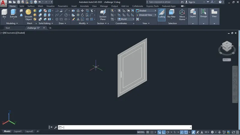
- Extrude it as you can see below fig. I selected the object which i want to extrude
- I Extrude it 3"
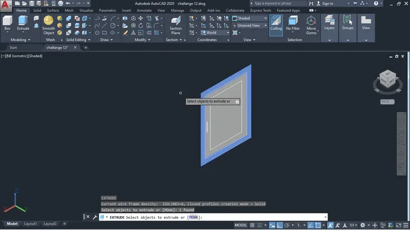
- again go with extrude it by 2"
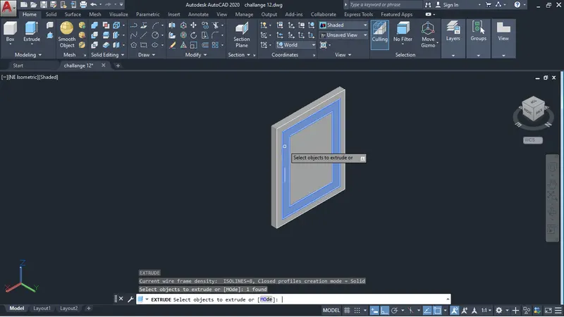
- Againt extrude the panel by .5"
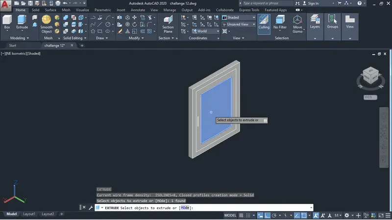
- after move the mulions inside the frame and also move the panel inside to like window frame with door
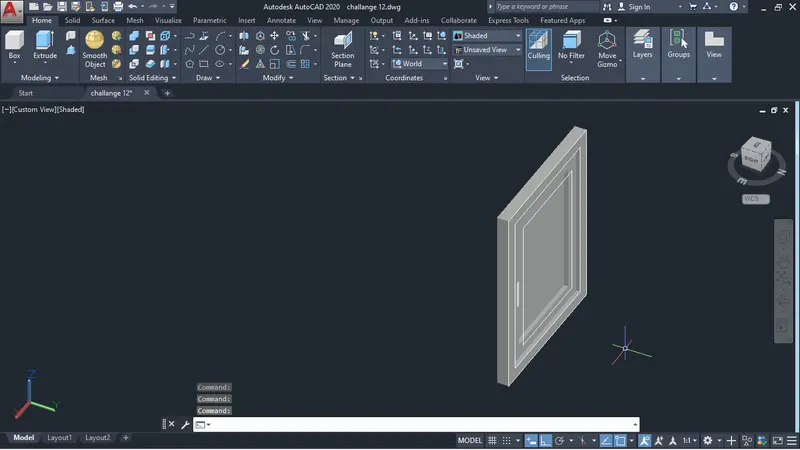
- after that go to 2D wireframe and make the copy of window
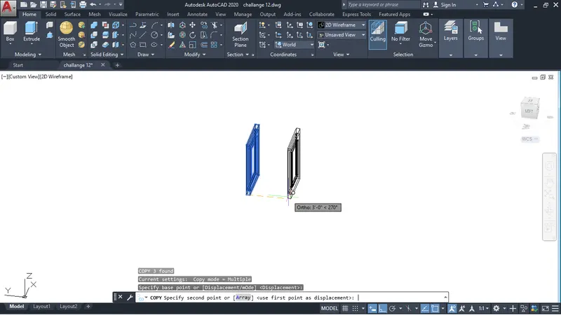
- put the copy window in the corner of wall where window spacing is given
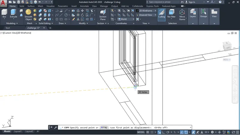
- Similary as above what we have done for Section-A window as we can do for Section-B window
- put it where second wall spacing given
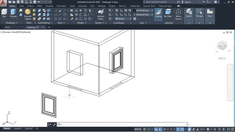
- after puting move the window inside 3"
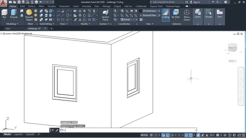
- after that go with Hide command your fig. look like as below .
Aim: Create the 3D View of the Building Façade as given in the plan and elevation. Also, see the detail of the window.
- I am using imperial template
- Set unit to Engineering by command-UN
- in top view draw rectangle (6'9"X10'9")
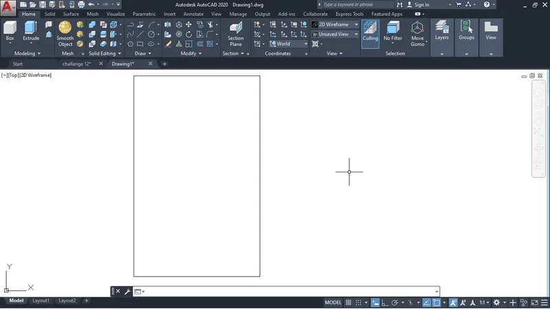
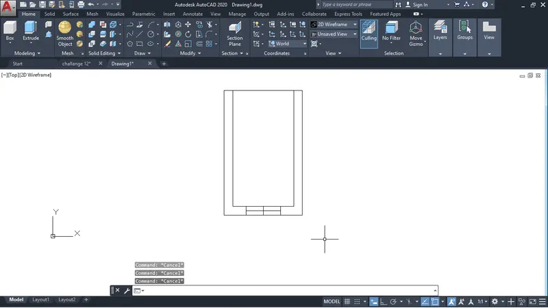
- with the help of offset and line tool make plan
- put the hatch in wall by command-H
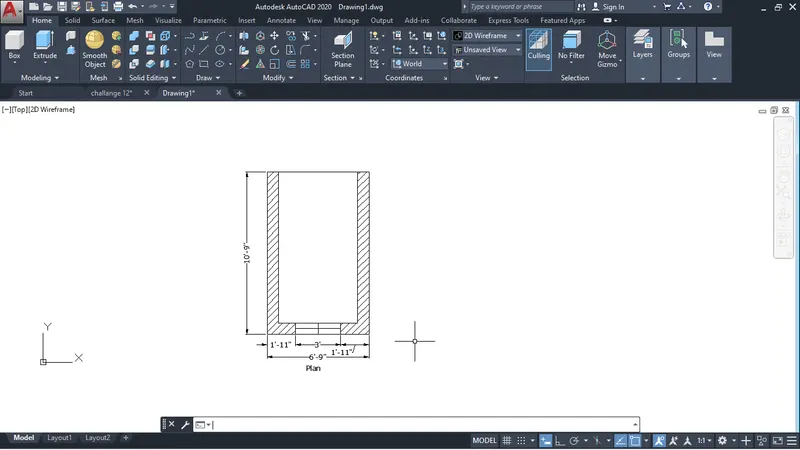
- After making plan with help of construction line draw the elevation
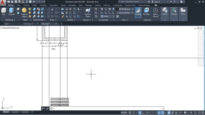
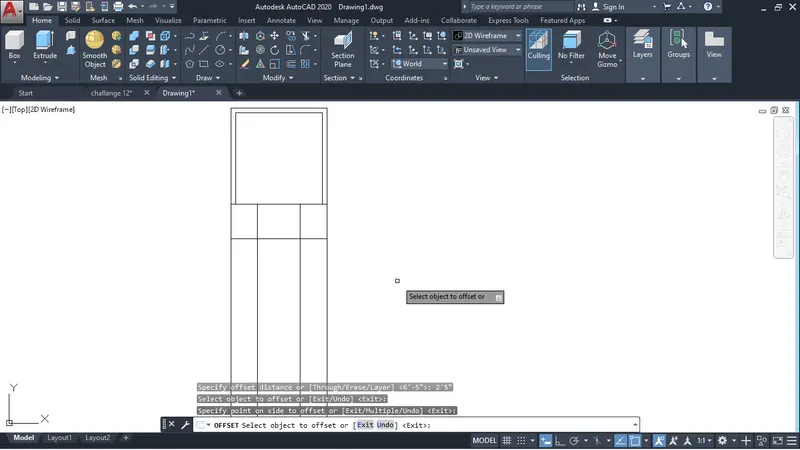
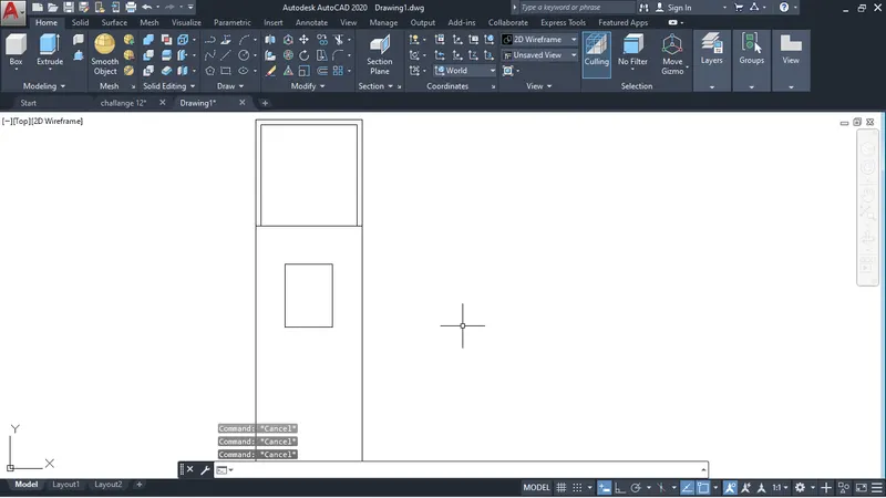
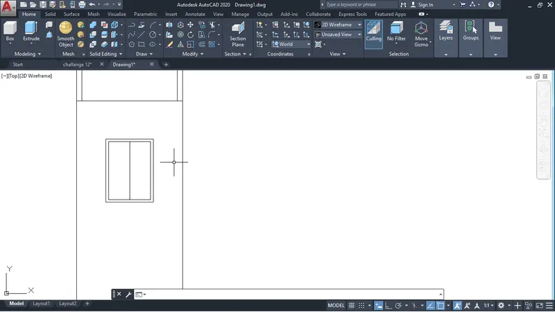
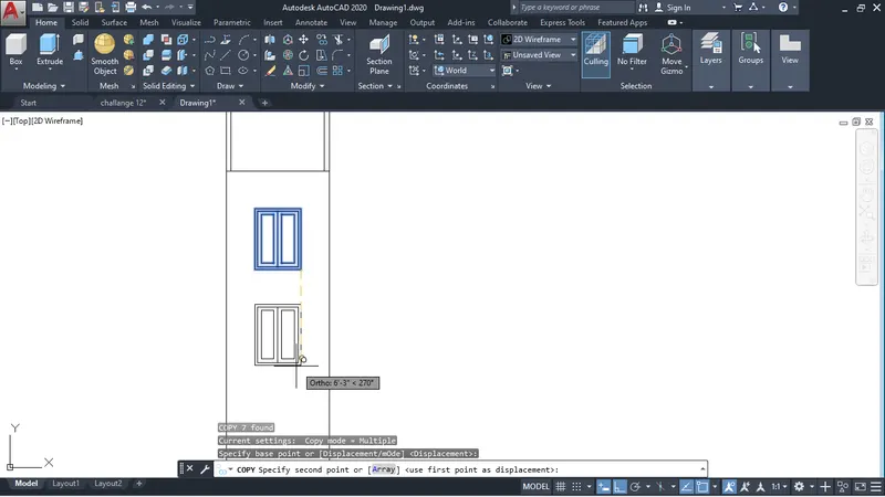
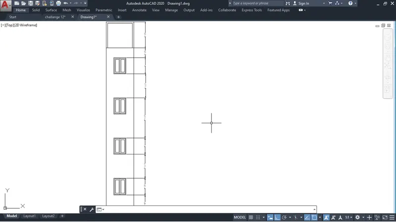
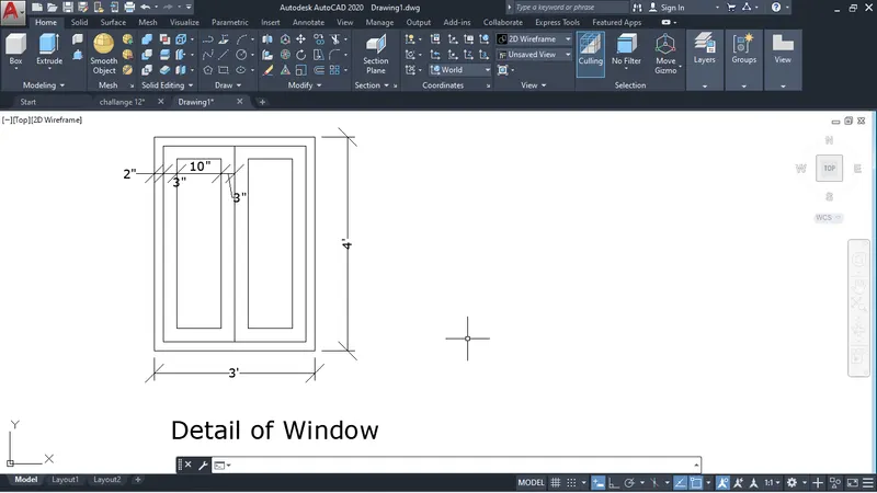
- After making elevation and window details go to default view
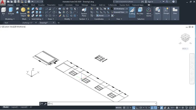
- make the copy of plan and delete the hatch
- make region by command-BO
- Extrude it at hieght 40'10"
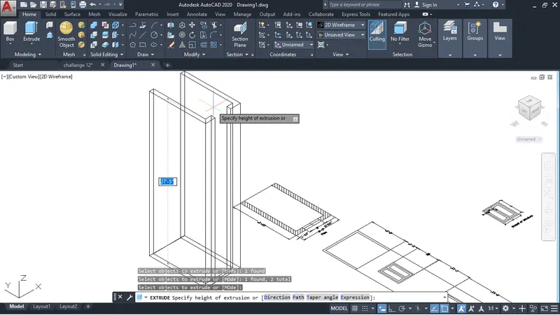
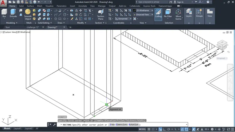
- make the rectangle for window portion as above fig.
- Extrude it at same height of the wall
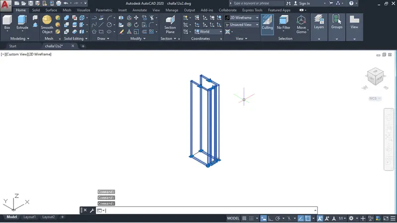
- now make Union of it
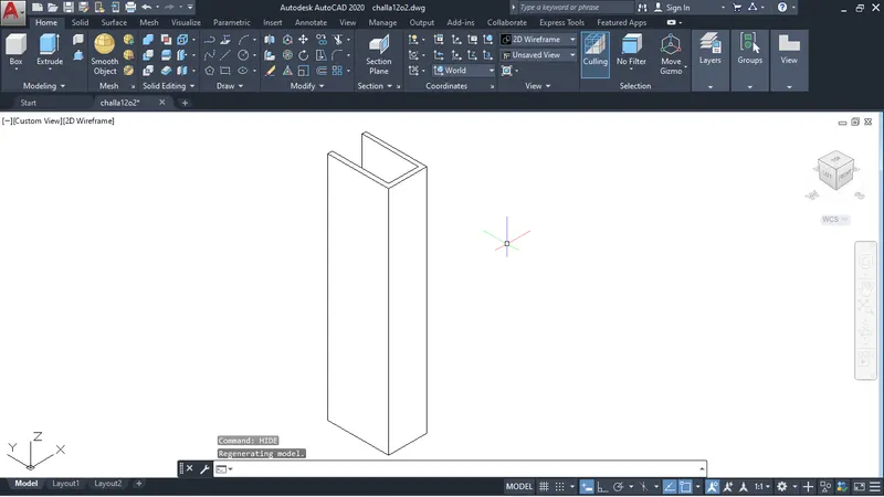
- go with Hide command it look like as below fig.
- Now make the copy of elevation put it in front of plan
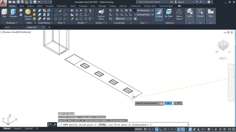
- delete all inside rectangle of window as you can see below fig
- Now make the region of all the left rectangle
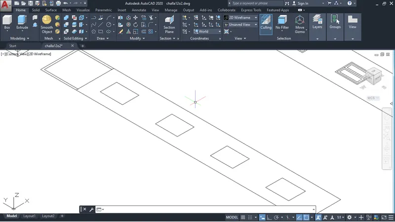
- After that rotate it by command-ROTATE3D OR 3DROTATE
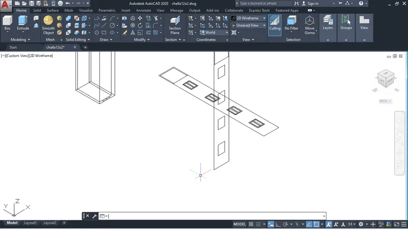
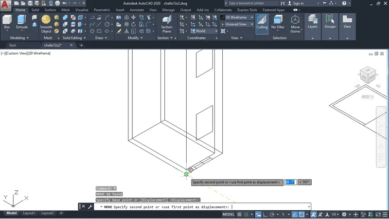
- move that in the corner of wall as you can see below fig.
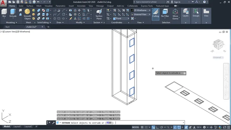
- Now extrude the rectangle -9" in z-axis
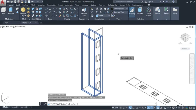
- Now go with command- SUBTRACT
- select object from to subtract
- select object to subtract
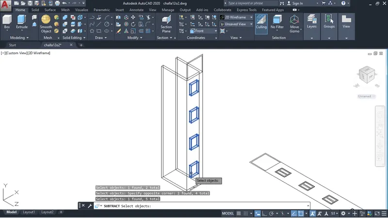
- after subtracting it look like as below fig.
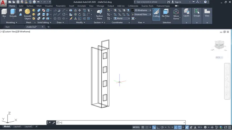
- when you go with Hide command It look like as below fig.
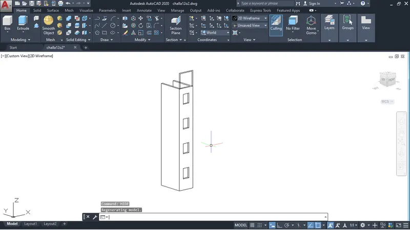
- Similary as above we have done for window we can do same here
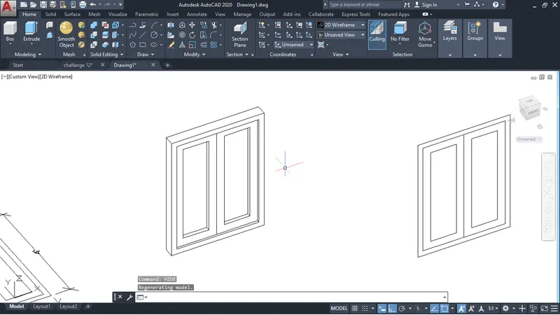
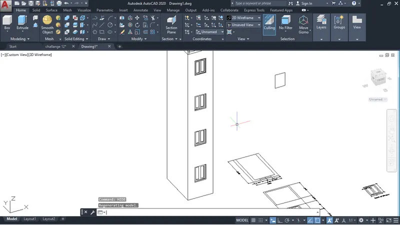
- After making window put it in the plan where window spacing is given
- move little inside
- after drawing will like as below fig.
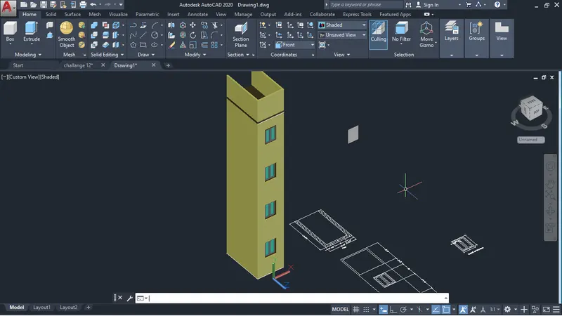
- you can also give color to wall and window etc.
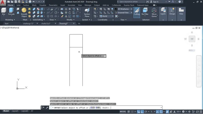
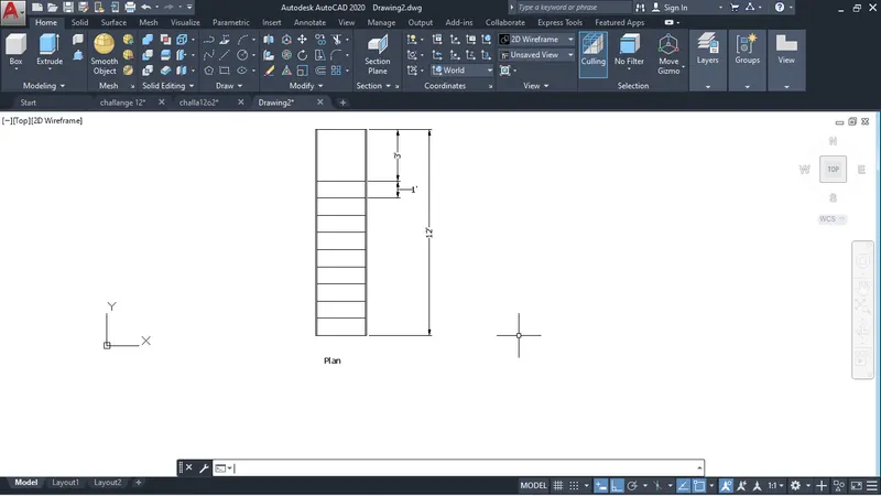
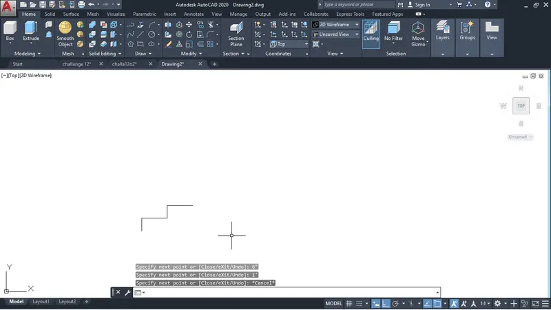
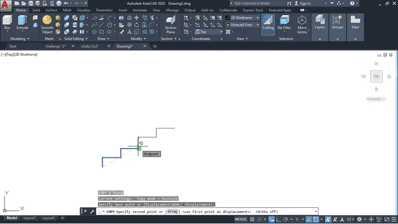
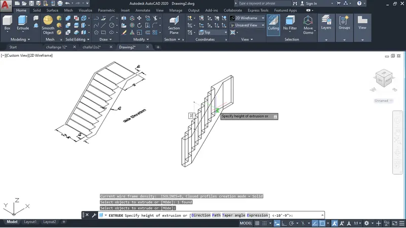
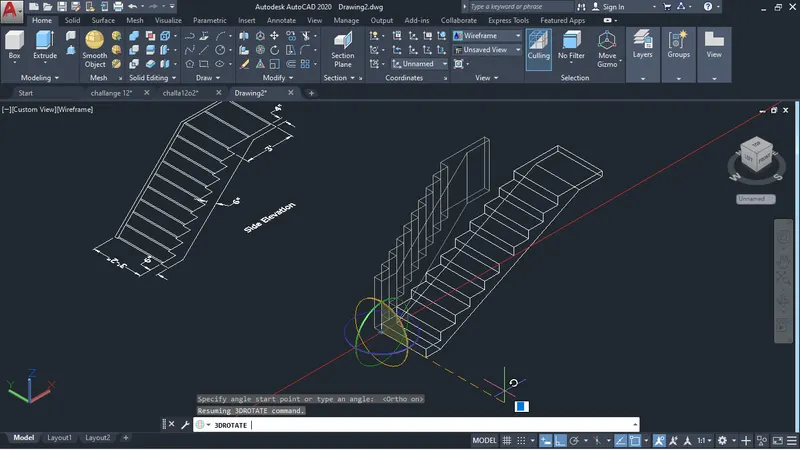
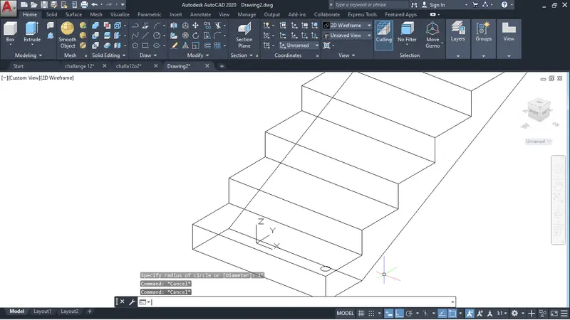
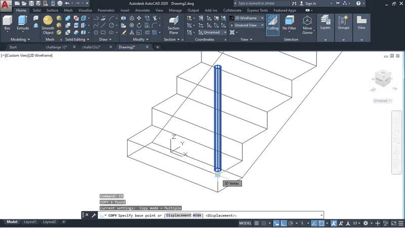
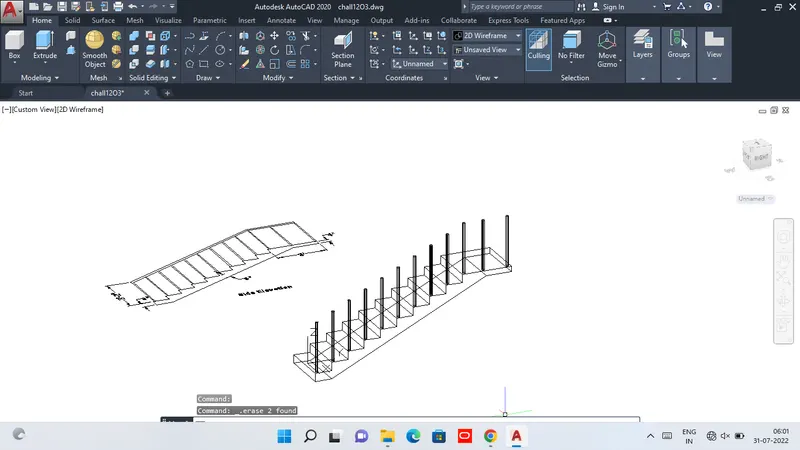
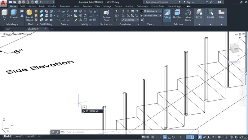
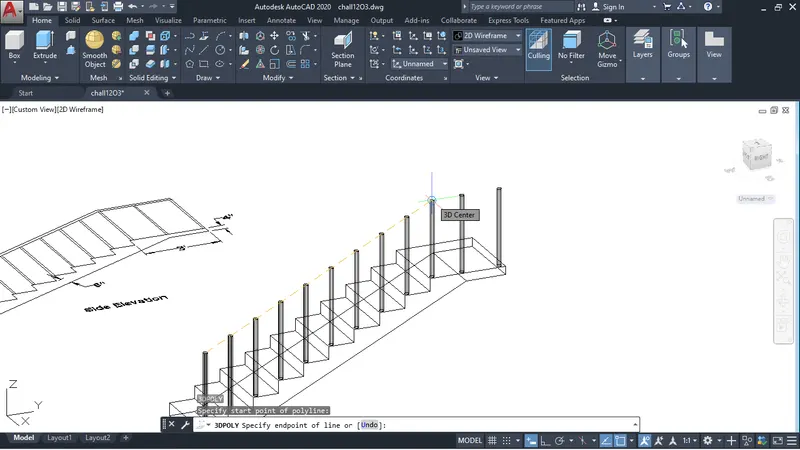
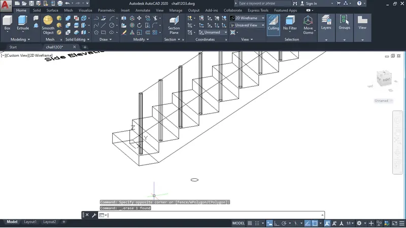
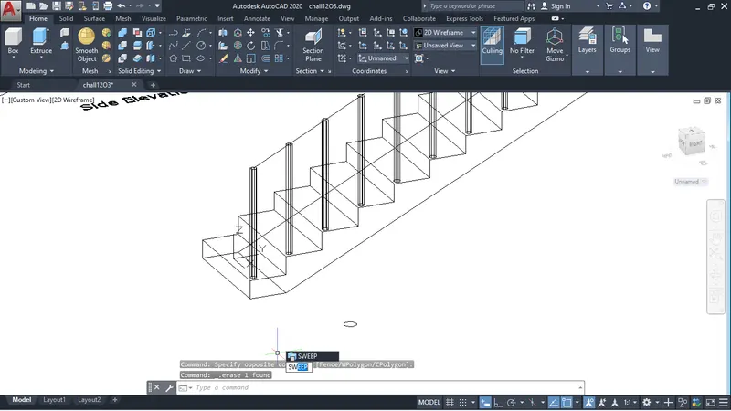
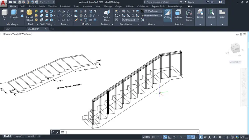
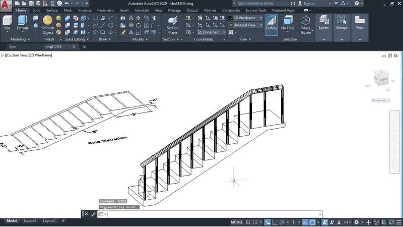
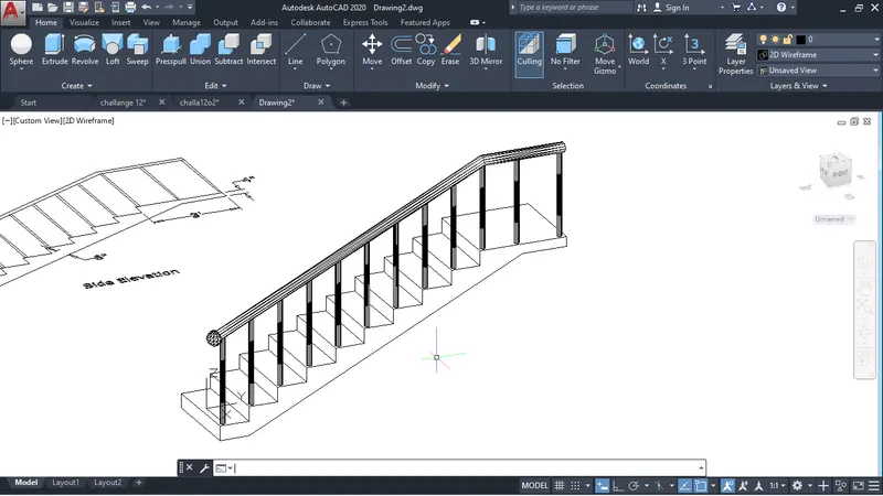
Aim: Create the ismoteric 3d view of a stair with railing as shown in the plan and elevation. Assume the size of the balustrades and the hand rails.
- I am using imperial template
- Set unit to Engineering by command-UN
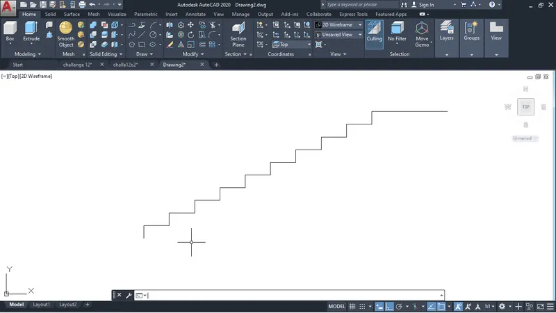
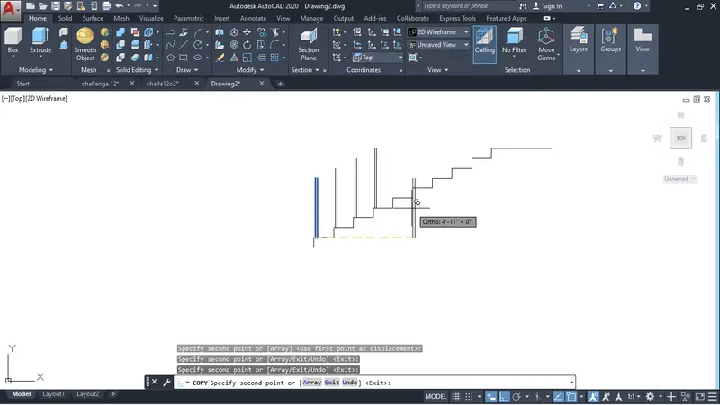
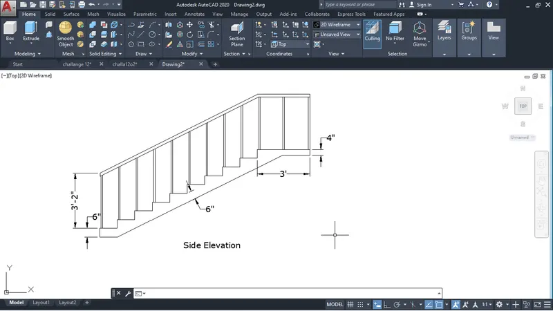
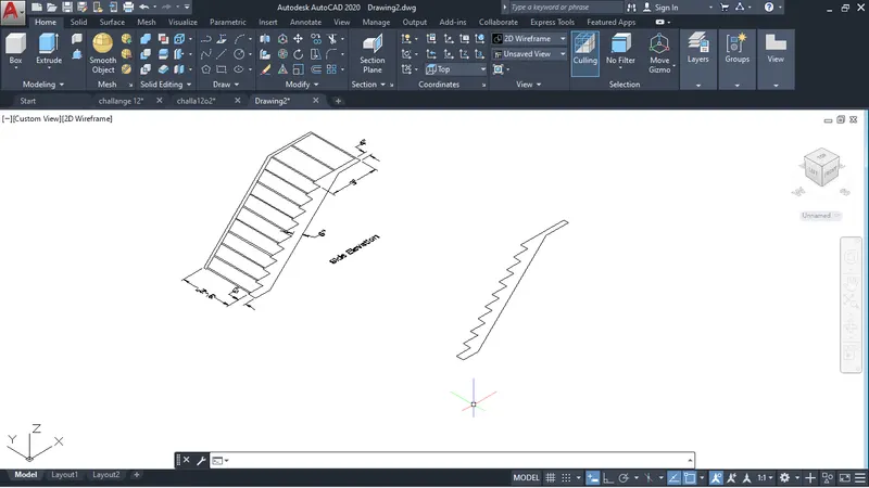
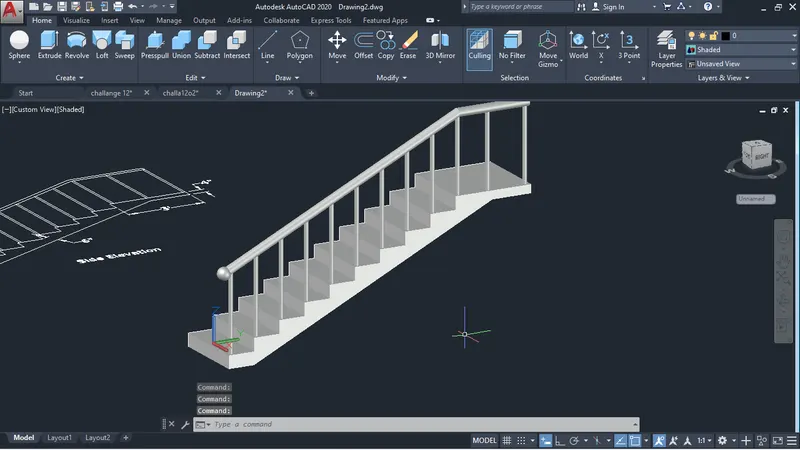
Aim: Create the 3D view of a Wall with spread footing . Create the Door opening only. Assume the size of the parpaet and the coping. See the plans and elevation for the details. Also, create a rendered view of the model with materials as of your choice.
- I am using imperial metric
- Set unit to Decimal by command-UN
- Go to top view
- make plane in top view
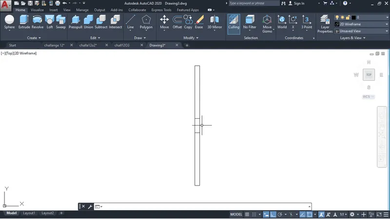
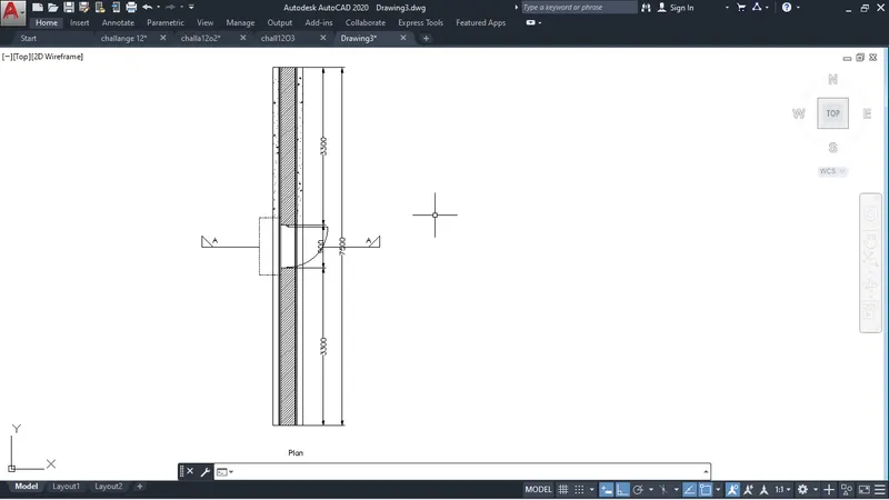
- Now with help of Command-Xl
- we draw the secttion of wall
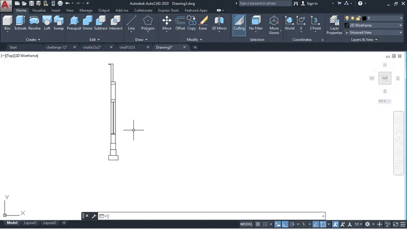
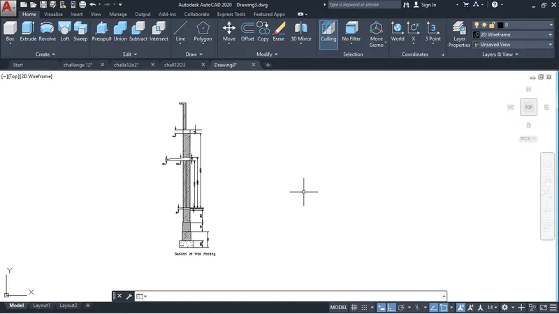
- After that go to default view
- make the copy of section of wall
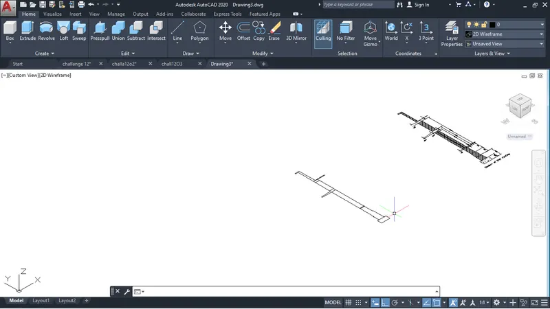
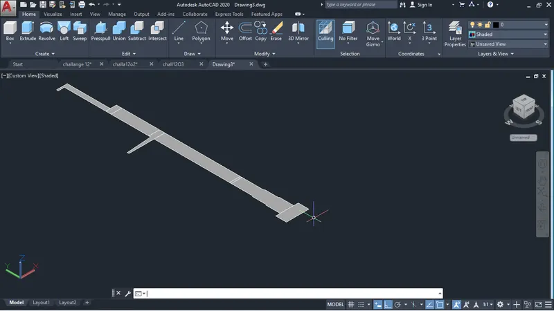
- make the region by command-BO
- after Extrude it at height 7500mm
- after that rotate it by command-3DROTATE
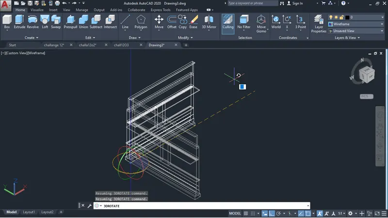
- after making drawing as below fig.
- Now assign the material
- to assign material go with command-MAT
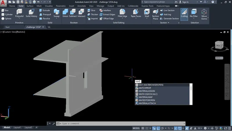
- When you give MAT command a there will be pop-up screen
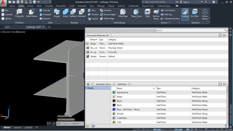
- In that pop-up you can select type of material you want
- in above fig. you can see Autodesk Library
- When you click on that there will be different type of material as you see below fig
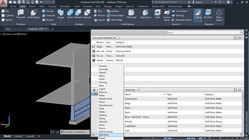
- now Assign the select the section
- after selection you can click on the material it will be assign
- Or right click on the material from mouse then click on assign to selection
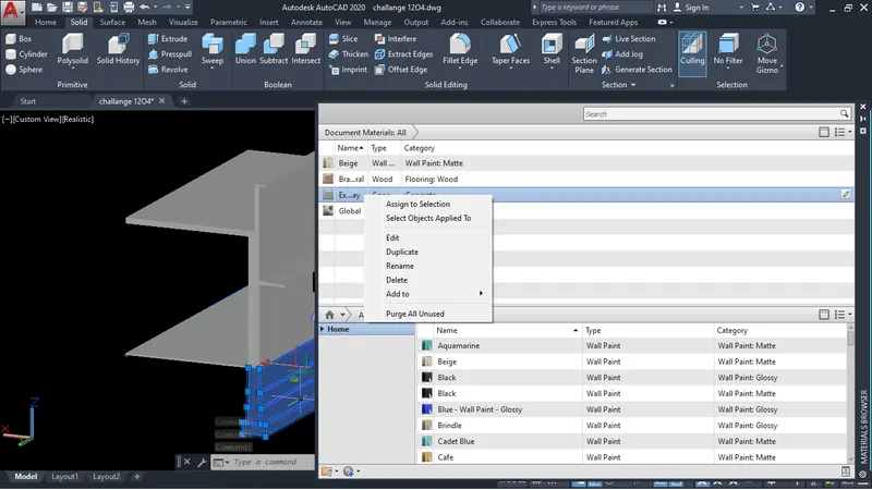
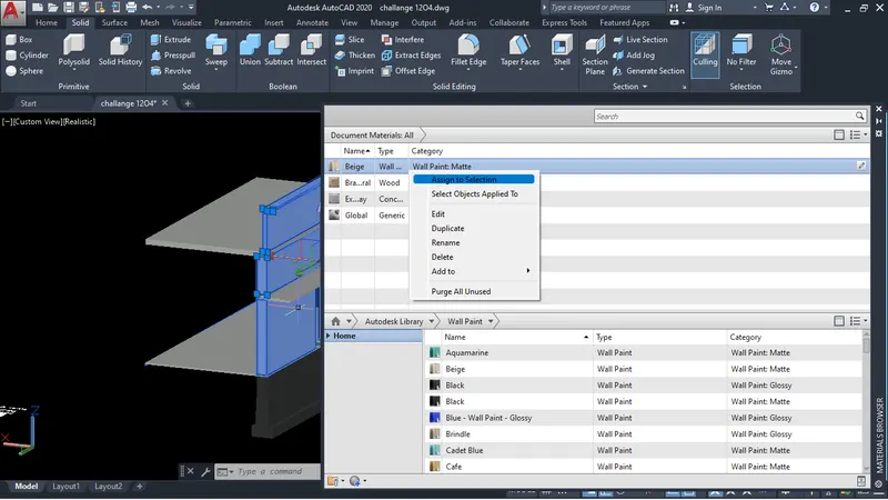
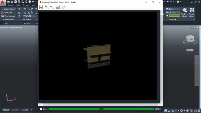
- after assigning all the material You can render that by command-RENDER OR RR
- Now I make some design to it look good
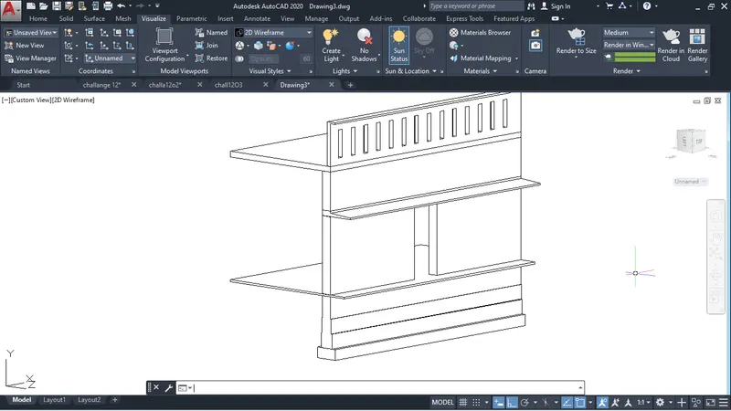
- You can also some environmental effect to rendering.