Creating 3D Isometric view of various structural elements in AutoCAD
1. Create a 3D Isometric View of the building with plan and elevation given.
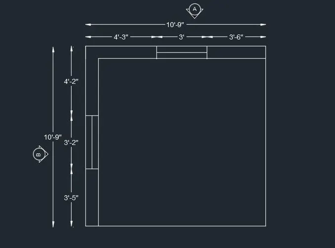
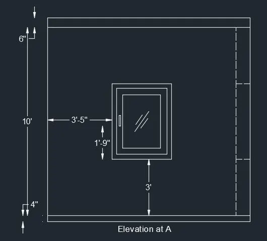
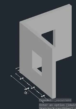
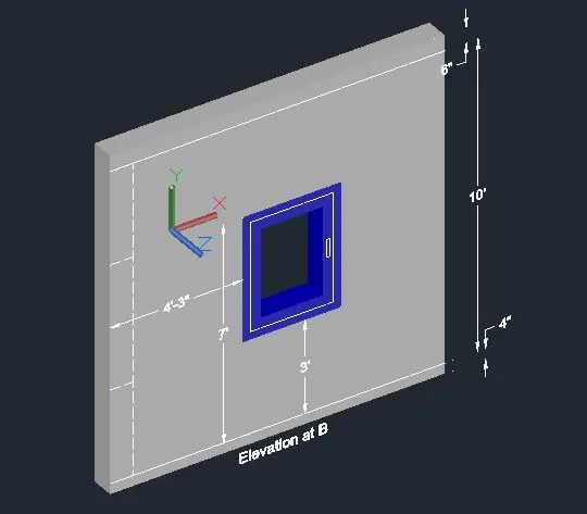
.open autocad and open new page
.unit command and set engineering , precision 0' 0" and unit inches
.d(dimension style manager ) command and set primary unit engineering and precision 0'0"
.using line command , trim command , offset command , rotate 3d command, extrude command ,subtract command, dimension command and multiline text command we draw the above image
.shapemode command and choose shaded and hit enter.
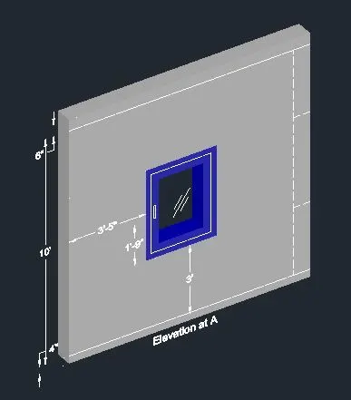
2. Create the 3D View of the Building Façade as given in the plan and elevation. Also, see the detail of the window.
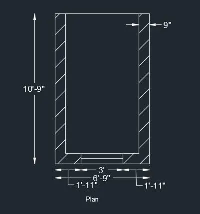
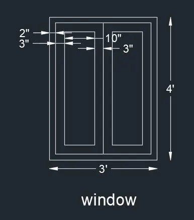
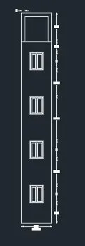
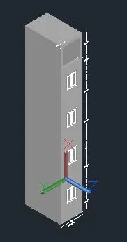
.open autocad and open new page
.unit command and set engineering , precision 0' 0" and unit inches
.d(dimension style manager ) command and set primary unit engineering and precision 0'0"
.using line command , trim command , offset command ,hatch command, rotate 3d command, extrude command ,subtract command, dimension command and multiline text command we draw the above image
.shapemode command and choose shaded and hit enter.
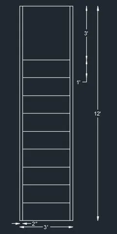
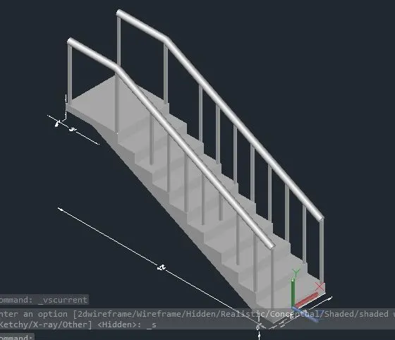
3. Create the ismoteric 3d view of a stair with railing as shown in the plan and elevation. Assume the size of the balustrades and the hand rails.
assume baluster and hand rail dia is 2"
width of staircase is 3'
riser=6"
tread =1'
.open autocad and open new page
.unit command and set engineering , precision 0' 0" and unit inches
.d(dimension style manager ) command and set primary unit engineering and precision 0'0"
.using line command , trim command ,fillet command, offset command ,copy command,sweep command, extrude command, dimension command and multiline text command we draw the above image.
.shapemode command and choose shaded and hit enter.
4. Create the 3D view of a Wall with spread footing . Create the Door opening only. Assume the size of the parpaet and the coping. See the plans and elevation for the details. Also, create a rendered view of the model with materials as of your choice.
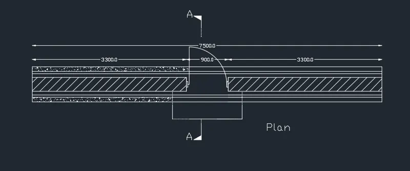
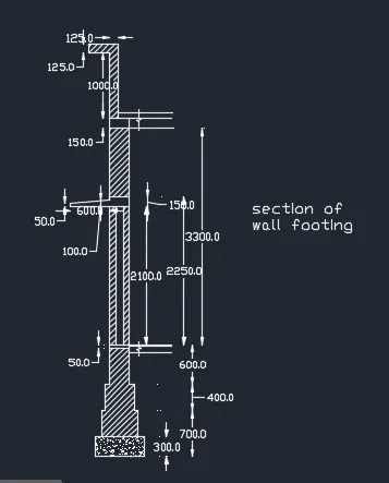
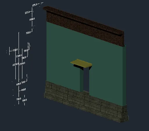
.open autocad and open new page
.unit command and set decimal, precision 0.0 and unit millimeter
.d(dimension style manager ) command and set primary unit decimal and precision 0.0
.using line command , trim command , offset command ,copy command, extrude command, dimension command and multiline text command we draw the above image.
.for rengdering purpose:
.1st of all we have to apply material color.
. go to visulaize > material > material browser
.choose Aquamarine,concrete block, and canary and apply them as shown in image
.command rr(render) , select region> pick crop window and apply rendering
.after rendering we got 3rd image uploaded above.