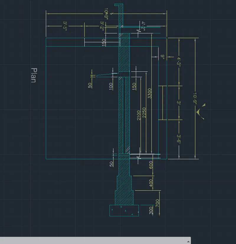
Creating 3D Isometric view of various structural elements in AutoCAD
Aim:- To create a 3d isometric view of given building with plan and elevation
COMMANDS USED:-
- extrude
- OFFSET
- UCS
- box
- union
- subtract
- move
- 3d orbit
- loft
- sweep
- cone
- region
procedure:-
- open the autocad ,click on workspace switching and change it to 3d modelling and click on the home buttonnear the view cube
- create a box by clicking from the toolbar or box command click on length give the length as 3' and width 2'6"
- type plan command so that front face is aligned corrctly
- move the rectangle to the line drawn earlier 2" from the right side of front view . by rectangle command draw a rectangle of dimension 32" and 2'4"
- move the rectangle to the line drawn earlier 2" from the right of the face
- DELETE the line created earlier now with command 3d orbit
- select the rectangle
- extrude the rectangle to z axis 2'4" leaving 2" thickness
- dimensions are given by dim linear
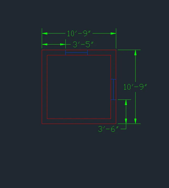
STEP -2:-
- create a box by clicking from the toolbar or box command click on length give the length as 3' and width 2'6"
- type plan command so that front face is aligned corrctly
- move the rectangle to the line drawn earlier 2" from the right side of front view . by rectangle command draw a rectangle of dimension 32" and 2'4"
- move the rectangle to the line drawn earlier 2" from the right of the face
- DELETE the line created earlier now with command 3d orbit
- select the rectangle
- extrude the rectangle to z axis 2'4" leaving 2" thickness
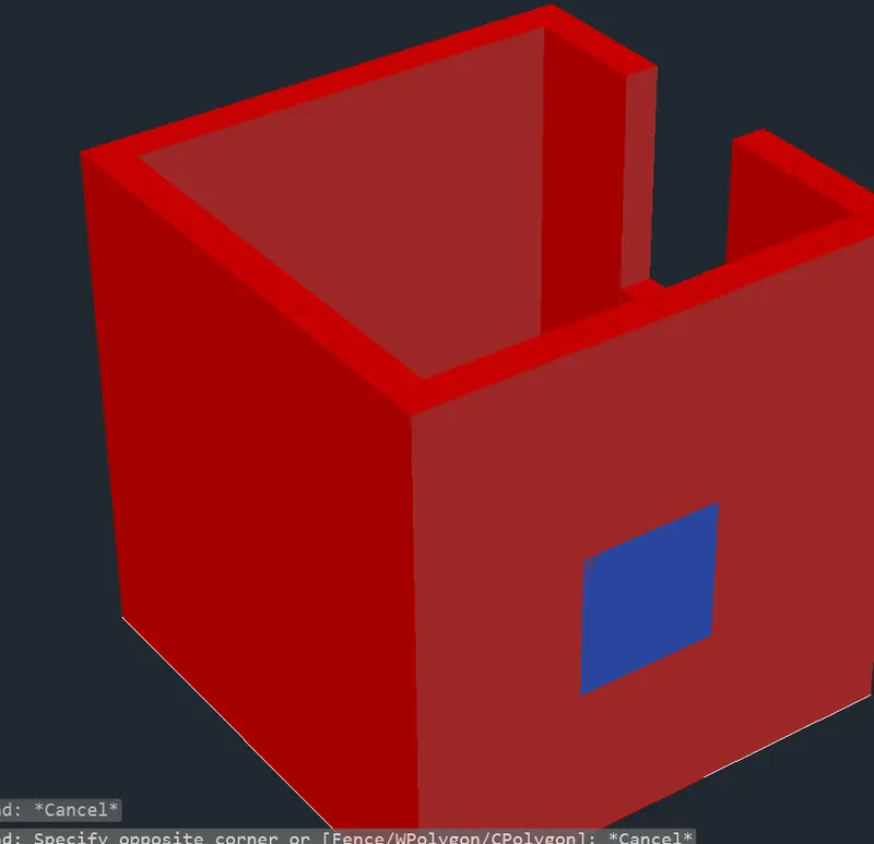
STEP:-3
- type plan command so that front face is aligned corrctly
- move the rectangle to the line drawn earlier 2" from the right side of front view . by rectangle command draw a rectangle of dimension 32" and 2'4"
- move the rectangle to the line drawn earlier 2" from the right of the face
- DELETE the line created earlier now with command 3d orbit
- select the rectangle
- extrude the rectangle to z axis 2'4" leaving 2" thickness
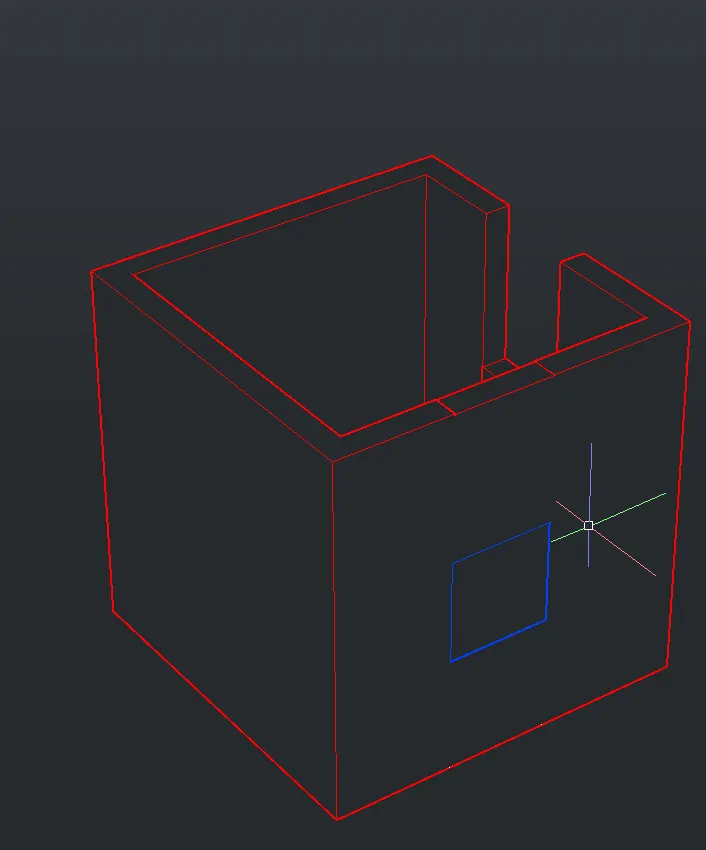
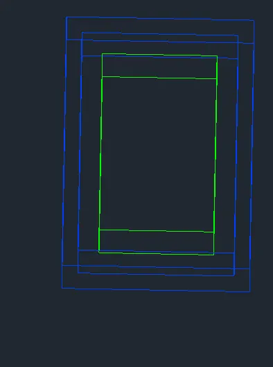
ELEVATION:-1
ELEVATION-2
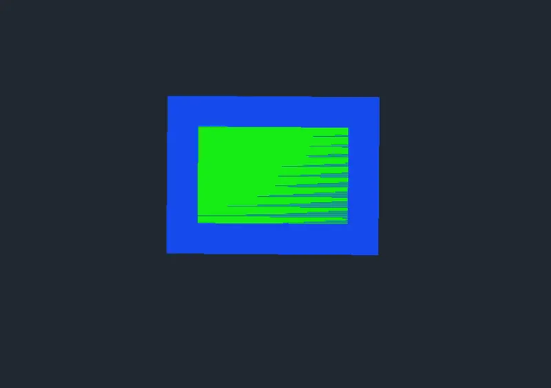
RESULT:- above drawing are the result
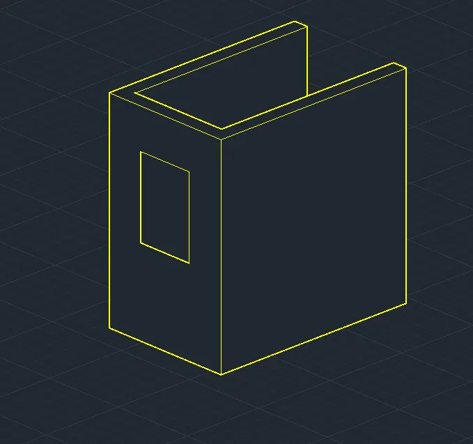
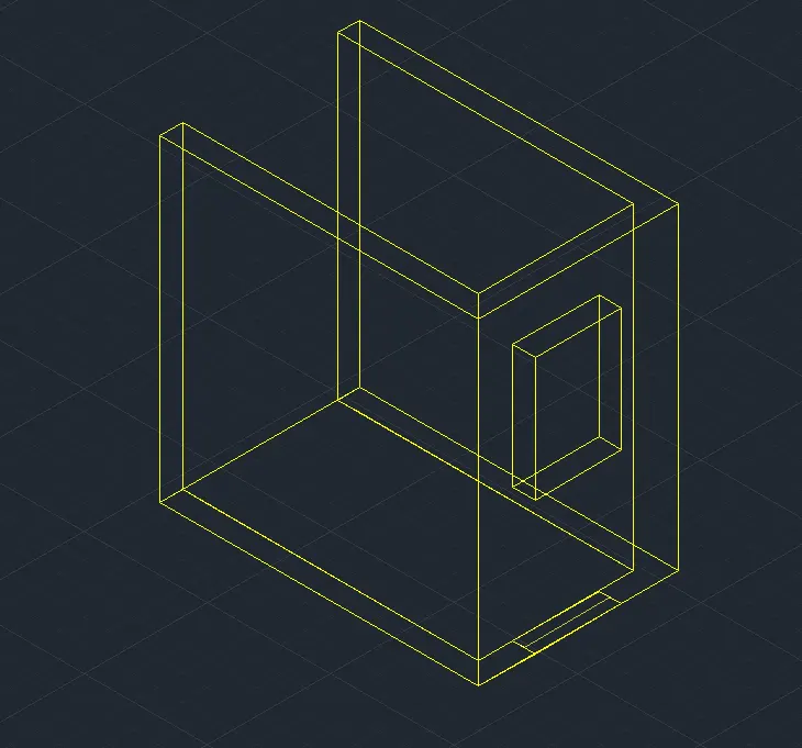
AIM:- creating 3d view of the building facade as given in the plan and elevation . also see the detail of window
COMMAND USED:-
- extrude
- OFFSET
- UCS
- box
- union
- subtract
- move
- 3d orbit
- loft
- sweep
- cone
- region
procedure:-
- open the autocad ,click on workspace switching and change it to 3d modelling and click on the home buttonnear the view cube
- create a box by clicking from the toolbar or box command click on length give the length as 3' and width 2'6"
- type plan command so that front face is aligned corrctly
- move the rectangle to the line drawn earlier 2" from the right side of front view . by rectangle command draw a rectangle of dimension 32" and 2'4"
- move the rectangle to the line drawn earlier 2" from the right of the face
- DELETE the line created earlier now with command 3d orbit
- select the rectangle
- extrude the rectangle to z axis 2'4" leaving 2" thickness
- dimensions are given by dim linear
STEP-2:-
- create a box by clicking from the toolbar or box command click on length give the length as 3' and width 2'6"
- type plan command so that front face is aligned corrctly
- move the rectangle to the line drawn earlier 2" from the right side of front view . by rectangle command draw a rectangle of dimension 32" and 2'4"
- move the rectangle to the line drawn earlier 2" from the right of the face
- DELETE the line created earlier now with command 3d orbit
- select the rectangle
- extrude the rectangle to z axis 2'4" leaving 2" thickness
- dimensions are given by dim linear
STEP-3
- offset 9" for outer walls and using the line offset trim
- Extend the and draw the floor plan
- Now draw the windows using line command and rectangle
- USe copy command`
- Windows are drawn by Using Line command
- Section lines are drawn by using layer and changing the layer type
- FOr hatching the coolumns tyoe hatch in the command box -open setting - select pattern-select patternas air -CONC-select global scale
- ofset it to distance of 4"
- In command prompt type rec 2'*2'
- In command prompt type rec to draft the columns
- IN ribbon tab >annotate >text to text the given dimension
- Now ADD text and name the doors and windows and dimensions the plot size using D text and dimlin command
- Dimension-for drawing dimension using dimension tool in the ribbon
STEP-4:-
- create a box by clicking from the toolbar or box command click on length give the length as 3' and width 2'6"
- type plan command so that front face is aligned corrctly
- move the rectangle to the line drawn earlier 2" from the right side of front view . by rectangle command draw a rectangle of dimension 32" and 2'4"
- move the rectangle to the line drawn earlier 2" from the right of the face
- DELETE the line created earlier now with command 3d orbit
- select the rectangle
STEP-5
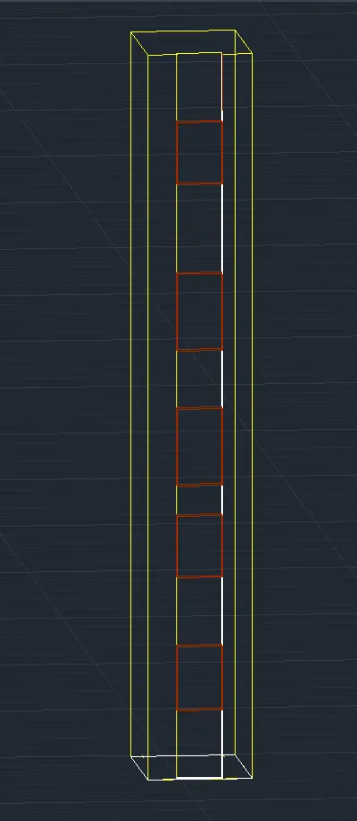
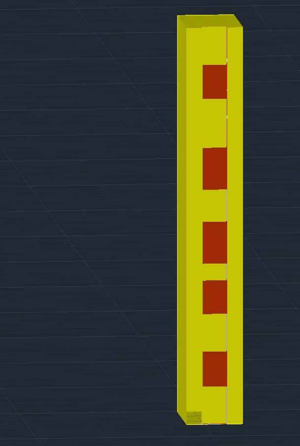
DETAIL of a window:-
RESULT:-
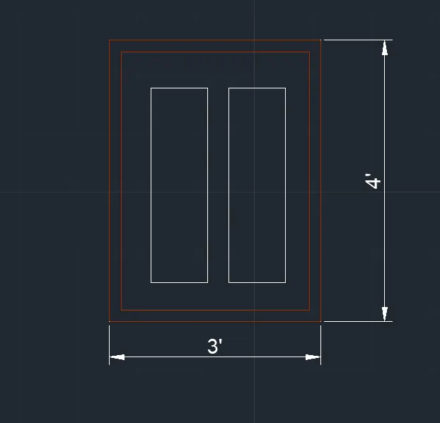
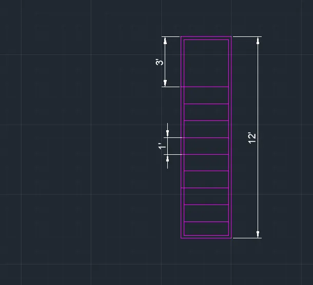
AIM:- creating 3d isometric view of a stair with railing as shown in plan and elevation assume the six
COMMAND USED:-
- extrude
- OFFSET
- UCS
- box
- union
- subtract
- move
- 3d orbit
- loft
- sweep
- cone
- region
procedure:-
- open the autocad ,click on workspace switching and change it to 3d modelling and click on the home buttonnear the view cube
- create a box by clicking from the toolbar or box command click on length give the length as 3' and width 2'6"
- type plan command so that front face is aligned corrctly
- create a box by clicking from the toolbar or box command click on length give the length as 3' and width 2'6"
- type plan command so that front face is aligned corrctly
- move the rectangle to the line drawn earlier 2" from the right side of front view . by rectangle command draw a rectangle of dimension 32" and 2'4"
- move the rectangle to the line drawn earlier 2" from the right of the face
- DELETE the line created earlier now with command 3d orbit
- select the rectangle
- extrude the rectangle to z axis 2'4" leaving 2" thickness
- dimensions are given by dim linear
- move the rectangle to the line drawn earlier 2" from the right side of front view . by rectangle command draw a rectangle of dimension 32" and 2'
- move the rectangle to the line drawn earlier 2" from the right of the face
- DELETE the line created earlier now with command 3d orbit
- select the rectangle
- extrude the rectangle to z axis 2'4" leaving 2" thickness
- dimensions are given by dim linear
-
STEP-2
- create a box by clicking from the toolbar or box command click on length give the length as 3' and width 2'6"
- type plan command so that front face is aligned corrctly
- move the rectangle to the line drawn earlier 2" from the right side of front view . by rectangle command draw a rectangle of dimension 32" and 2'4"
- move the rectangle to the line drawn earlier 2" from the right of the face
- DELETE the line created earlier now with command 3d orbit
- select the rectangle
- extrude the rectangle to z axis 2'4" leaving 2" thickness
- dimensions are given by dim linear
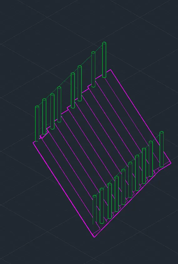
STEp-3
- create a box by clicking from the toolbar or box command click on length give the length as 3' and width 2'6"
- type plan command so that front face is aligned corrctly
- move the rectangle to the line drawn earlier 2" from the right side of front view . by rectangle command draw a rectangle of dimension 32" and 2'4"
- move the rectangle to the line drawn earlier 2" from the right of the face
- DELETE the line created earlier now with command 3d orbit
- select the rectangle
- extrude the rectangle to z axis 2'4" leaving 2" thickness
- dimensions are given by dim linear
RESULT:-
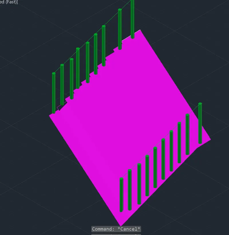
AIM:-
to create a 3d view of wall with spread footing and need to create a rendered view of material with standerds
COMMAND USED:-
- extrude
- OFFSET
- UCS
- box
- union
- subtract
- move
- 3d orbit
- loft
- sweep
- cone
- region
procedure:-
- open the autocad ,click on workspace switching and change it to 3d modelling and click on the home buttonnear the view cube
- create a box by clicking from the toolbar or box command click on length give the length as 3' and width 2'6"
- type plan command so that front face is aligned corrctly
- create a box by clicking from the toolbar or box command click on length give the length as 3' and width 2'6"
- type plan command so that front face is aligned corrctly
- move the rectangle to the line drawn earlier 2" from the right side of front view . by rectangle command draw a rectangle of dimension 32" and 2'4"
- move the rectangle to the line drawn earlier 2" from the right of the face
- DELETE the line created earlier now with command 3d orbit
- select the rectangle
- extrude the rectangle to z axis 2'4" leaving 2" thickness
- dimensions are given by dim linear
- move the rectangle to the line drawn earlier 2" from the right side of front view . by rectangle command draw a rectangle of dimension 32" and 2'
- move the rectangle to the line drawn earlier 2" from the right of the face
- create a box by clicking from the toolbar or box command click on length give the length as 3' and width 2'6"
- type plan command so that front face is aligned corrctly
- move the rectangle to the line drawn earlier 2" from the right side of front view . by rectangle command draw a rectangle of dimension 32" and 2'4"
- move the rectangle to the line drawn earlier 2" from the right of the face
- DELETE the line created earlier now with command 3d orbit
- select the rectangle
- extrude the rectangle to z axis 2'4" leaving 2" thickness
- dimensions are given by dim linear
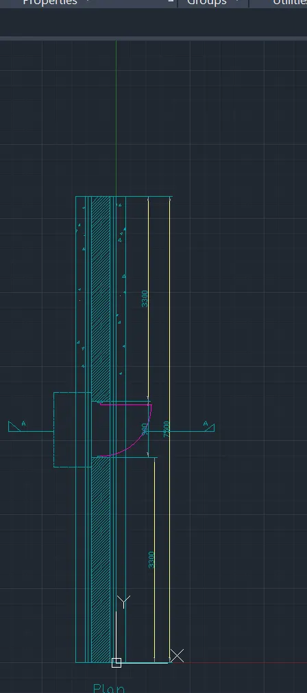
STEP-2
- create a box by clicking from the toolbar or box command click on length give the length as 3' and width 2'6"
- type plan command so that front face is aligned corrctly
- move the rectangle to the line drawn earlier 2" from the right side of front view . by rectangle command draw a rectangle of dimension 32" and 2'4"
- move the rectangle to the line drawn earlier 2" from the right of the face
- DELETE the line created earlier now with command 3d orbit
- select the rectangle
- extrude the rectangle to z axis 2'4" leaving 2" thickness
- dimensions are given by dim linear
RESULT:-