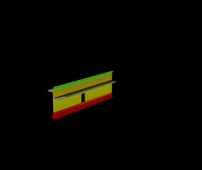
Creating 3D Isometric view of various structural elements in AutoCAD
1.)
- AIM
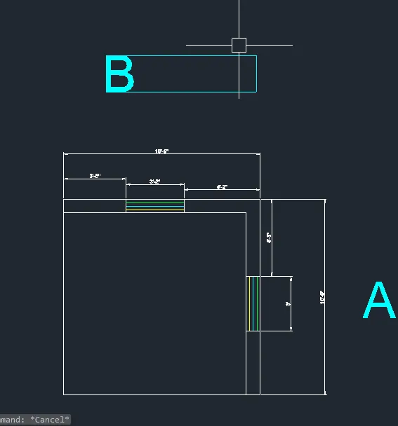
Create a 3D Isometric View of the building with plan and elevation given
- PROCEDURE
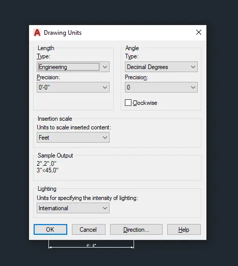
- Set the units
- use line commend
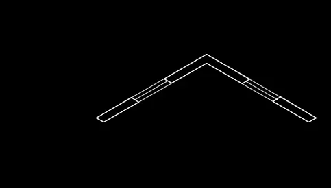
- Draw the plan usoing line commend
- Extrude the achived paln
- To the hight of 10'
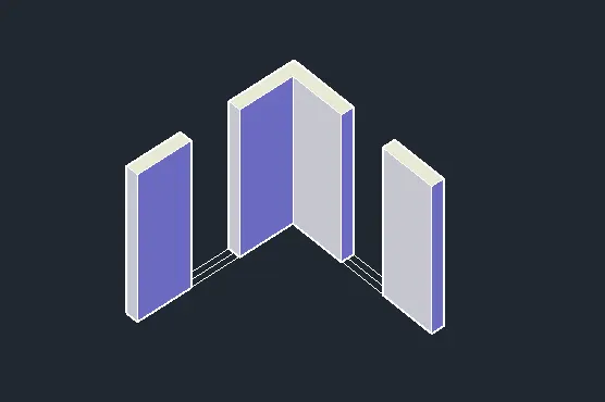
- Create the window using extrude
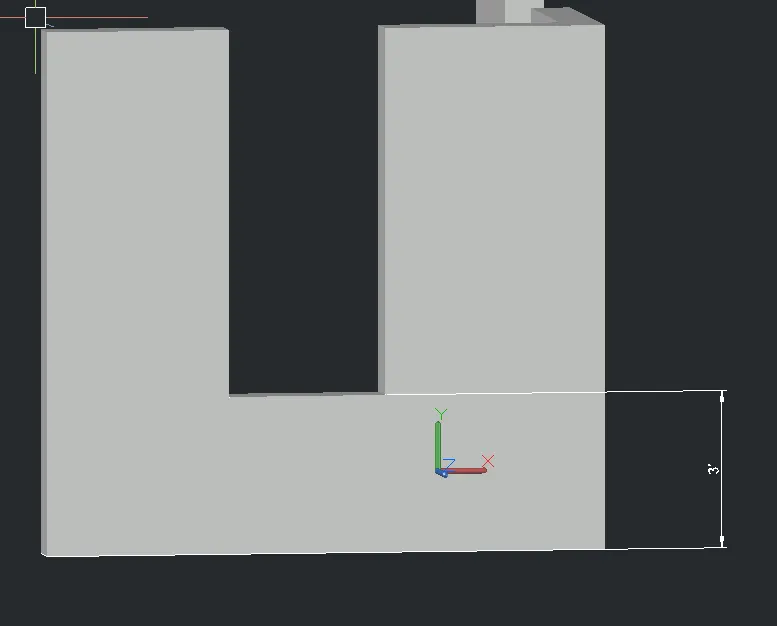
- creat thew opening
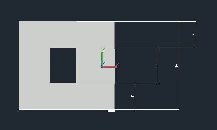
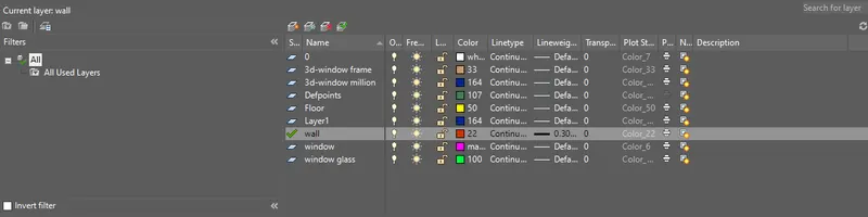
- creat the layers as per the needed
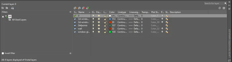
- put the colour to the wall
- crate teh window
- make the sectrion A
- Draw the section B
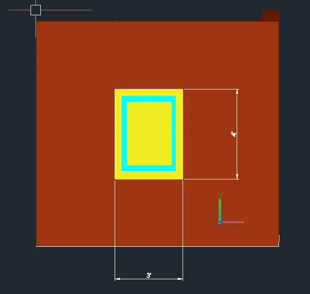
- RESULT
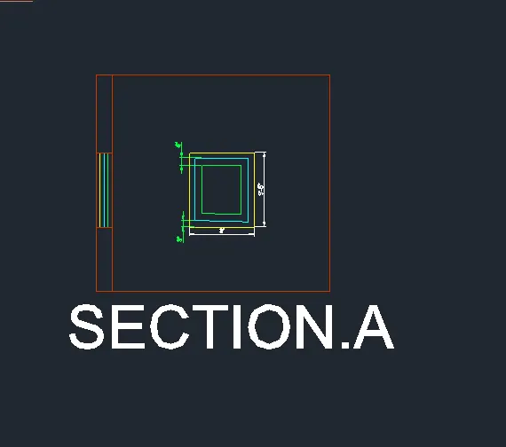
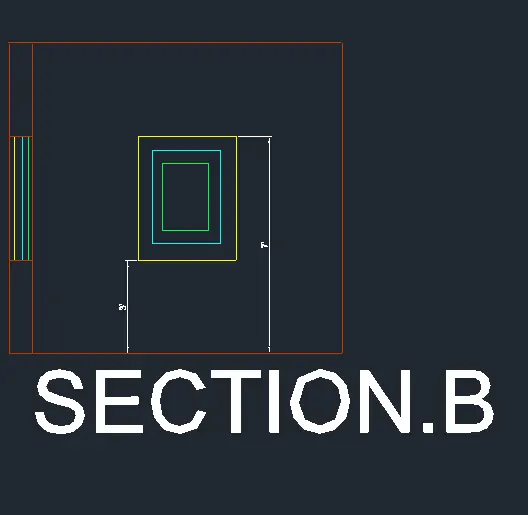
`
2.)
AIM
- To Create the 3D View of the Building Façade as given in the plan and elevation
Procedure
- SEt the units
- craet the layers
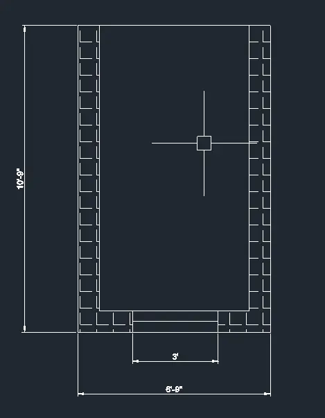
- Draw the layout
- Extrude the given layout
- hight to 42'5"
- Draw the openings as shown in the figure
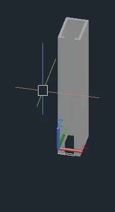
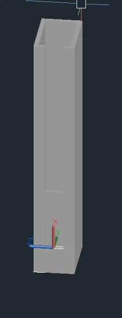
- Give the wall colour to the given form
- set the ucs for the every wall drawing
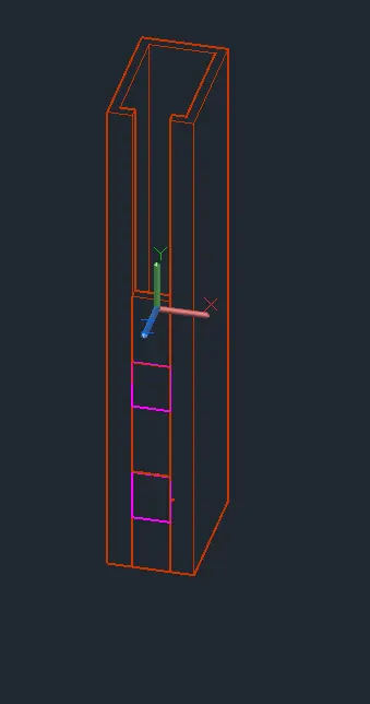
- creat the window and join in the layout
- produce the layout
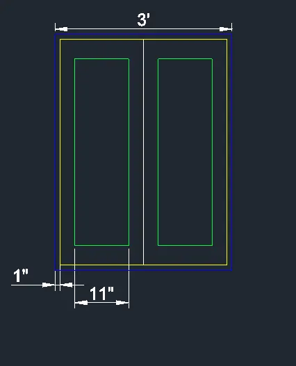
- Attach the window the the extruded wall
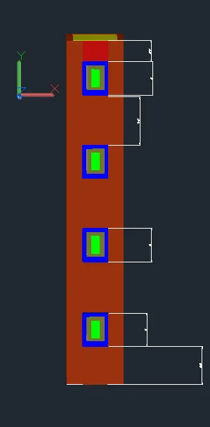
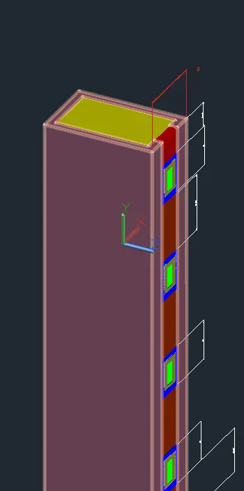
- Result
3.)
Aim
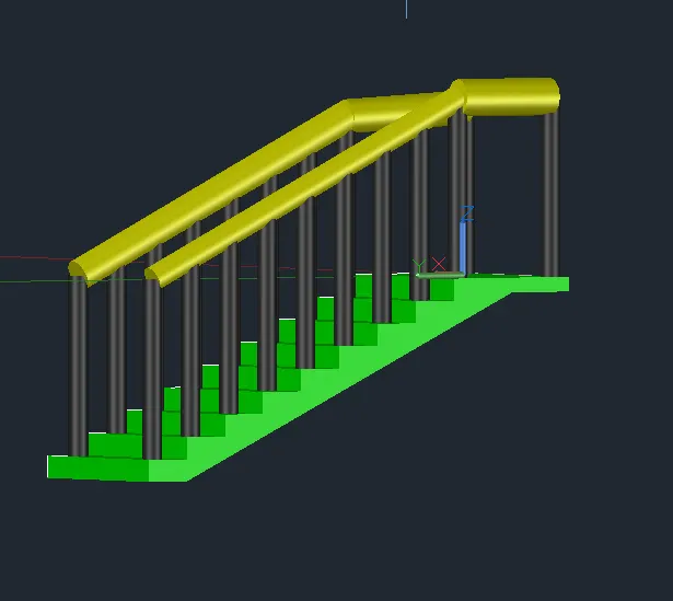
- Create the ismoteric 3d view of a stair with railing as shown in the plan and elevation
Procedure
- Set the units
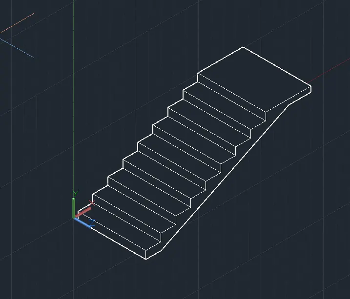
- Draw th estaircase lines
- extrude in the sw isometyric view
- RExtrude teh steps
- Give the dimensions
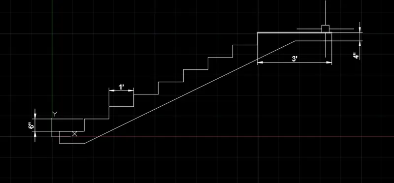
- extrude to the right side
- Set the ucs in the given object
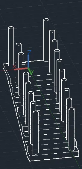
- Draw the rails circle
- Extrude the circle
- To the height of 4'5
- Provide the rails in both side
- copy th erails with base
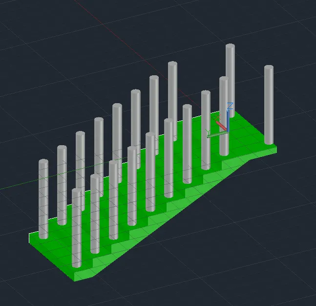
- Give the colour to the steps
- Also too the rails
- Provide the sweep to the rails
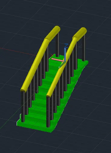
Result
5.)
Aim
Create the 3D view of a Wall with spread footing
Procedure
- Set the units
- Use the line commend and draw the wall
- Extrude the wall
- Make door opening
- Make render
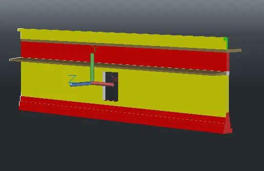
- Give colopu to the wall
- Use the ucs cvommend

- extrude the wall
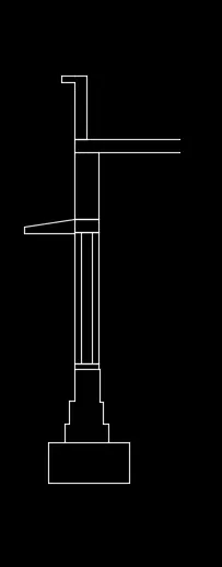
- Extrude and give the colours
- Fix the camera in the given position
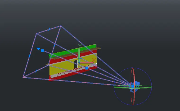
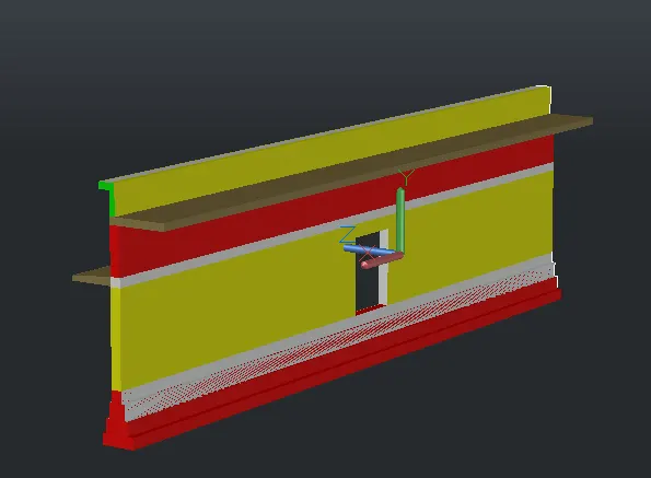
- Render in the given size
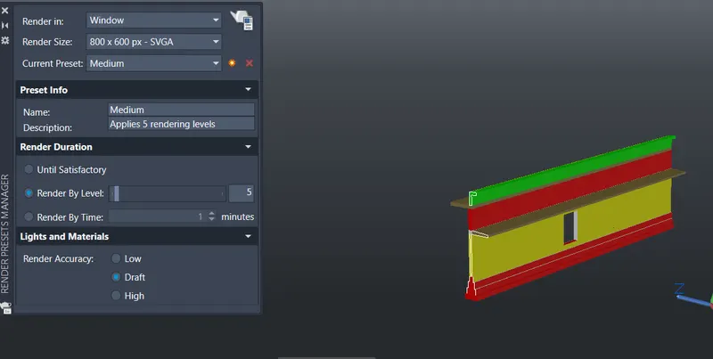
Result