Creating 3D Isometric view of various structural elements in AutoCAD
Aim of the project: To draw the given 3D figures.
The drawing in the project is done with help of AUTOCAD software.
Procedure:
Step 1: The units of the drawing sheet are set to Engineering precision.
Step 2: For the first question the dimensions lines are drawn using a spherical coordinate system.
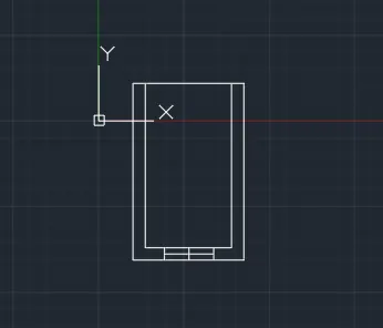
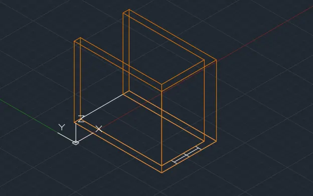
Step 3: the plan of the given drawing is drawn in 2D wireframe. and the extrude in 3 dimensional.
Step 4: layers are provided for differentiation as shown below.
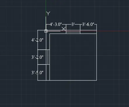
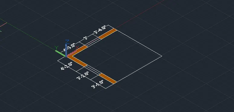
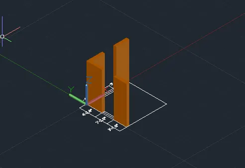
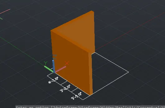
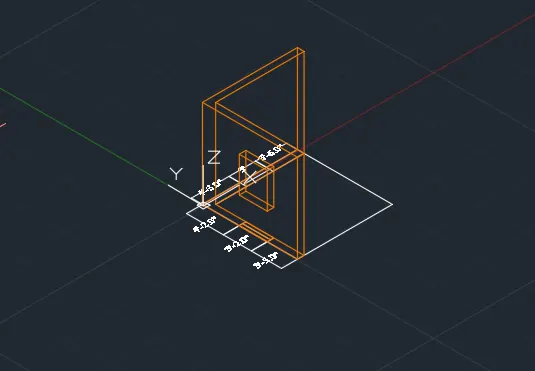
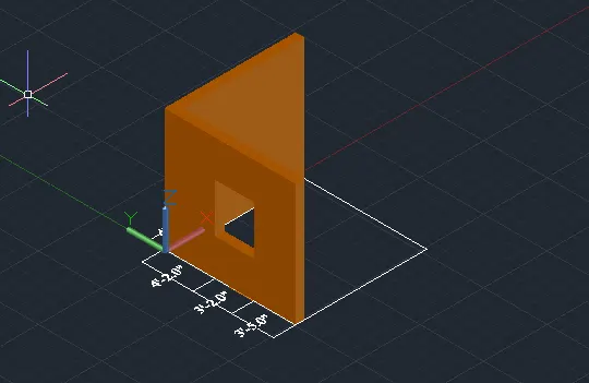
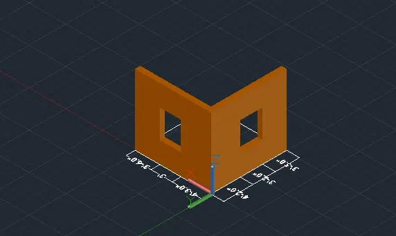
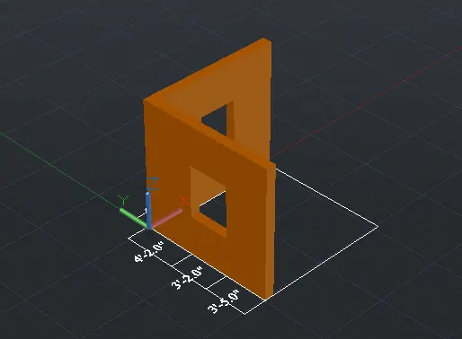
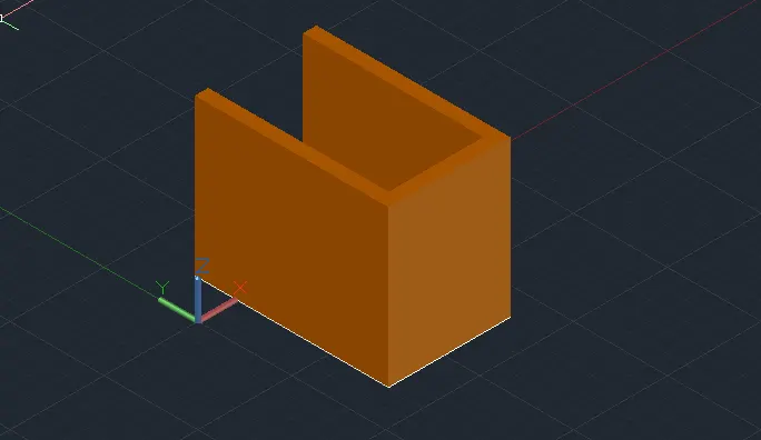
Step 5: For the second question, the plan is drawn in 2d wireframe and extruded in z-direction
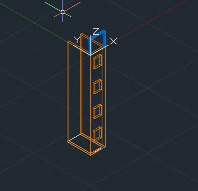
Step 6: the window sections are subtracted from the solid surface as shown below.

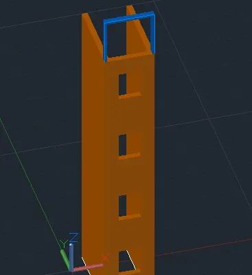
Step 7: To draw the staircase the plan is drawn in top view and rotated in the z-direction
Step 8: Boundary zone is created and the surface is extruded in the x direction as shown in the figure below.
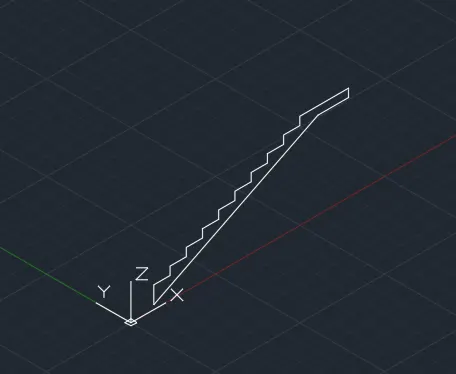
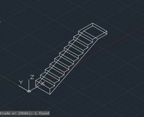
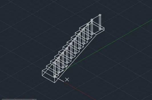
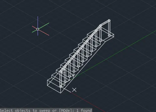
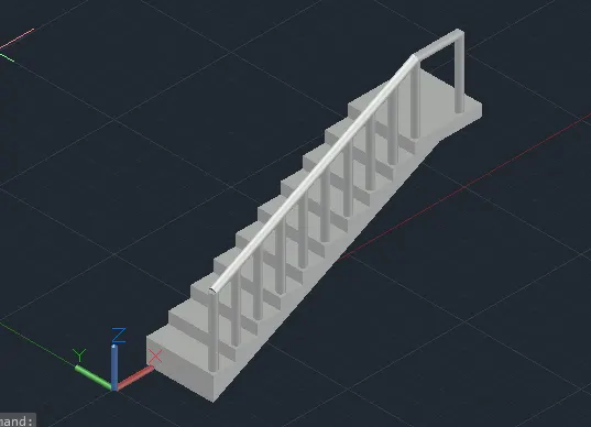
Step 9: For the isolated footing, the plan is drawn and extruded in the z-direction
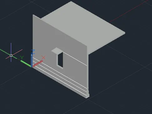
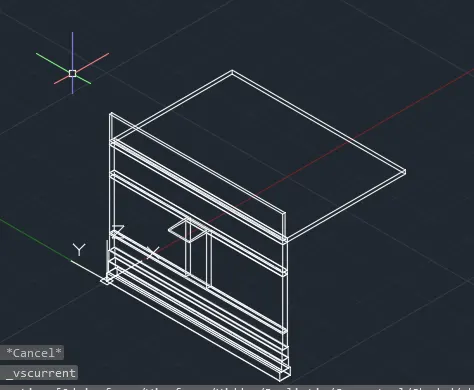
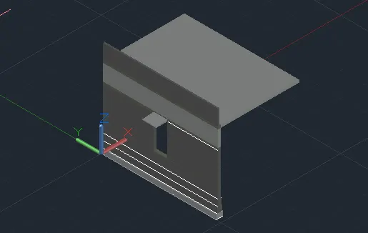
Step 10: the elevation and rendered view of the same is shown below.
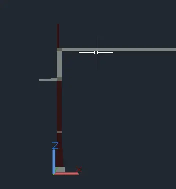
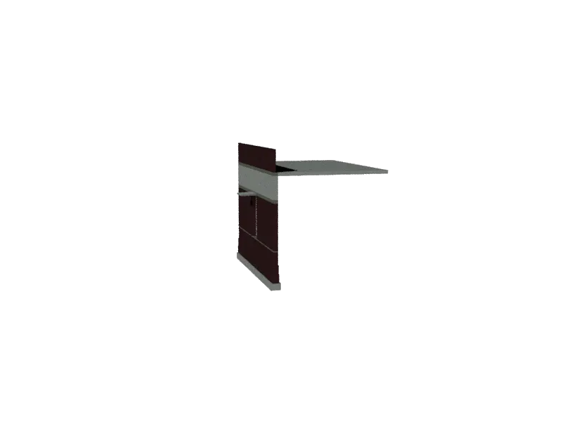
Results:
All the drawings are drawn from scratch and has been created using 3D modelling.