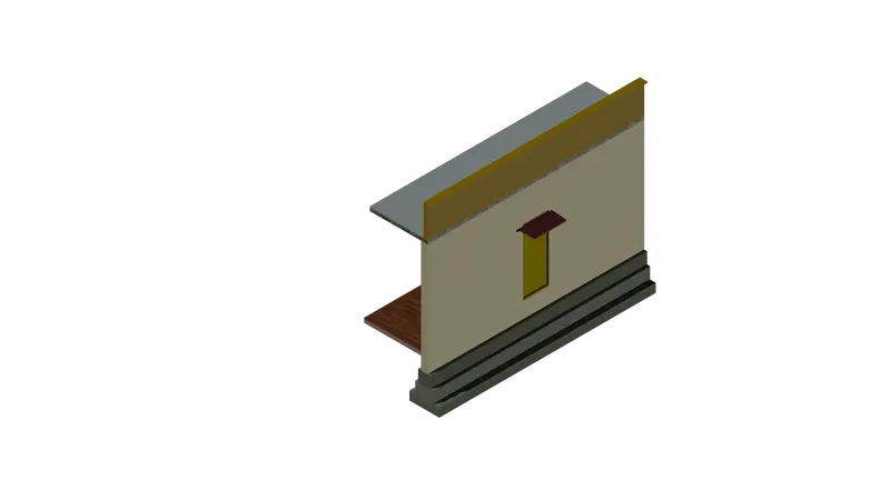
Creating 3D Isometric view of various structural elements in AutoCAD
1Q]
AIM: -
Create 3D Isometric View of given Building.
Use 3D modelling commands to draw the 3D model.
PROCEDURE: -
Start the AutoCAD with units as IMPERIAL
Set the Units to ENGINEERING
In RIBBON, got to VIEW palette.
In VIEW, go to Viewport tools and turn on the UCS icon, NAVIGATION bar, and VIEW CUBE
Switch the Workspace to 3D MODELLING.
Set the VIEW CONTROL to TOP
Type LAYERS
Create New Layer: 2D-Floor Plan
Assign Colour to the Layer.
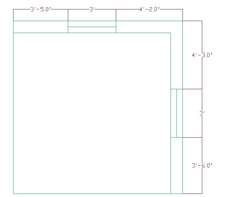
Draw the Floor Plan under the created Layer.
Type LINE
Specify 1st point: 0,0
Specify next point: 0,10'-9"
Specify next point: -10'-7",0
Type OFFSET
Provide the offset distance as 9" units to all the lines.
Use FILLET to trim the corners.
Type RECTANGLE
Choose 1st point: 0,3'-6"
Draw window with dimensions: 9" x 3' inside the wall
Draw second window
Choose 1st point: -4'2",10'9"
Draw window with dimesnsions: 3' x 9" units.
Draw the given plan with Drawing Tools and Modify Tools.
Set the VIEW CONTROL to FRONT
Type LAYERS
Create New Layer: 2D-Elevation
Assign Colour to the Layer.
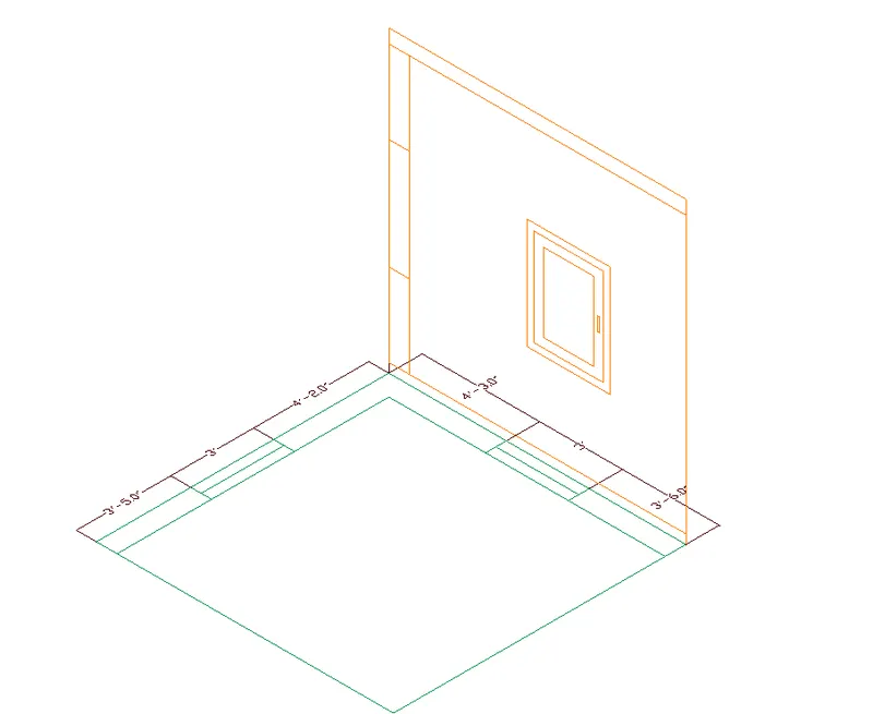
Draw the Elevations under the created Layer.
Type LINE
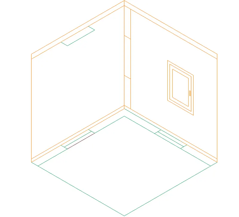
Draw the Elevation A and Elevation B as shown in figure by using DRAWING Tools and MODIFY Tools.
Set the VIEW CONTROL to SW ISOMETRIC
Move the Elevation plans to Floor Plan.
Type LAYERS
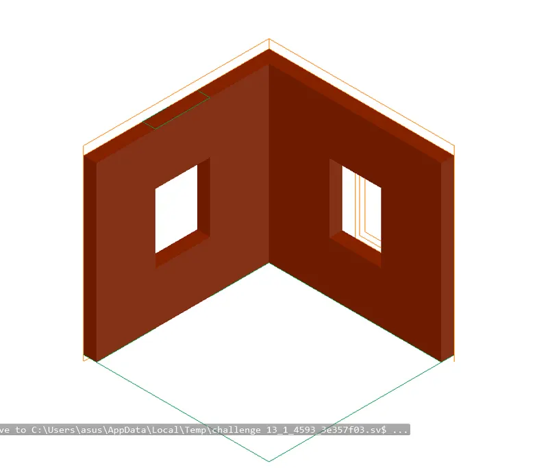
Create New Layer: 3D-WALLS
Assign Colour to the Layer.
Set the current Layer as 3D-WALLS
Type BOUNDARY
Object Type: Region
Pick points as the internal points on the WALLS.
Press Enter
Type LINE
Draw Rectangle over the windows under 3D-WALLS Layer.
Copy the Rectangles to the wall Height.
Press Enter.
Type EXTRUDE
Select the WALLS
Enter the Height for Extrusion: 10’ units.
Type EXTRUDE
Select the walls over windows.
Enter the Height for Extrusion: 3’ units.
Extrude walls over windows till Sill Level from Bottom
Extrude walls over windows from Top to Window Height.
Type UNION
Select all the 3D-WALLS drawn
Press Enter
Type LAYERS
Create New Layer: 3D-SLAB
Turn off the mentioned Layers
1)3D-walls
2)2D-Elevation
Set the Current Layer as 3D-SLAB
Type RECTANGLE
Draw Rectangle over the Floor plan.
Type BOUNDARY
Object Type: Region
Pick points as the internal points on the SLAB.
Press Enter
Type EXTRUDE
Select the 3D-slab
Enter the Height for Extrusion: 4” units.
Type COPY
Select the 3D-slab
Choose the base point
Specify the point: @0,0,10’
Select the 3D-slab and go to properties
Change the HEIGHT to 6” units.
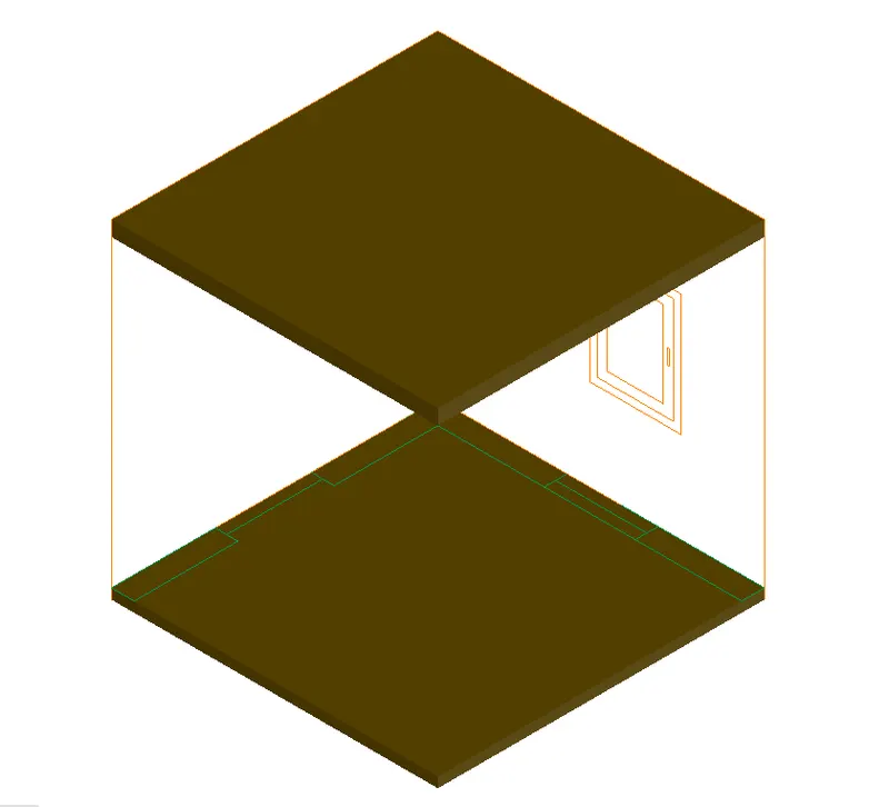
Turn on all the Layers.
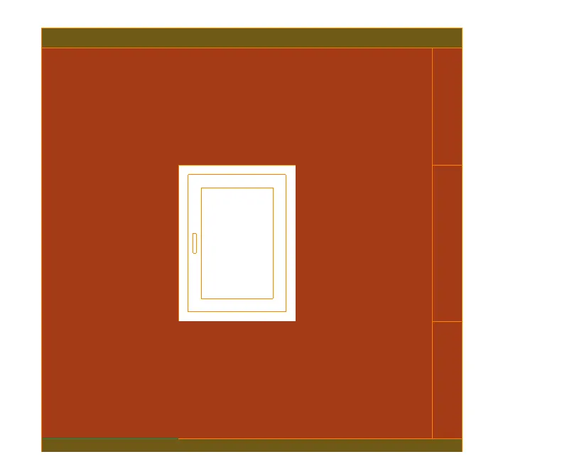
Create the Window for Elevation A
Type LAYERS
Create New Layer: 3D-Window Frame
Assign Colour to the Layer
Create New Layer: 3D-Window Mullion
Assign Colour to the Layer
Create New Layer: 3D-Window Glass
Assign Colour to the Layer.
Select the 3D-Window Frame as Current Layer
Type BOUNDARY
Object Type: Region
Pick points as the internal points on the Window.
Press Enter
Type SUBTRACT
Select the Outer panel of window
Press Enter
Select the Inner panels of window to subtract
Press Enter
Type SUBTRACT
Select the 2nd panel of window
Press Enter
Select the Inner panel of window to subtract
Press Enter
Type MOVE
Select all the Window panels
Select the Base Point
Specify the next point: @0,0, -4”
Press Enter
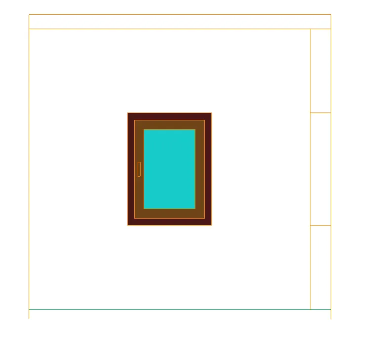
Create the Window for the Elevation B
Select the 3D-Window Frame as Current Layer
Type BOUNDARY
Object Type: Region
Pick points as the internal points on the Window.
Press Enter
Type SUBTRACT
Select the Outer panel of window
Press Enter
Select the Inner panels of window to subtract
Press Enter
Type SUBTRACT
Select the 2nd panel of window
Press Enter
Select the Inner panel of window to subtract
Press Enter
Type MOVE
Select all the Window panels
Select the Base Point
Specify the next point: @0,0, -4”
Press Enter
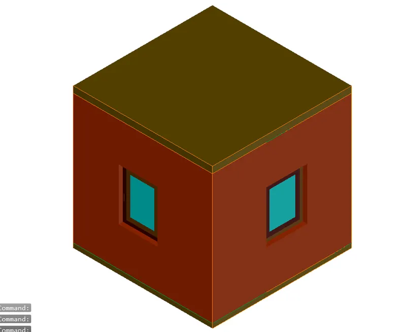
RESULT: -
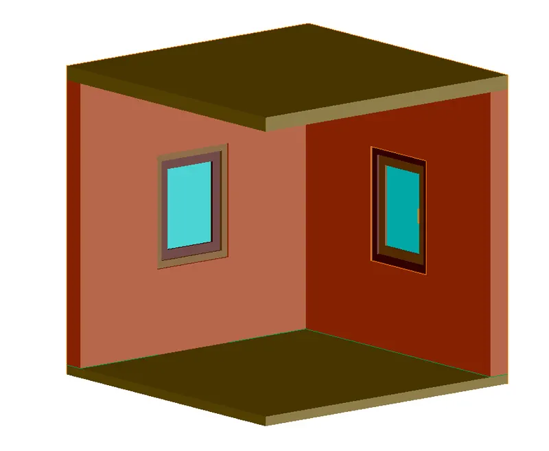
We created the 3D ISometric View of Building with given plan and Elevations.
2Q]
AIM: -
Create 3D Isometric View of the Building Facade.
Use 3D modelling commands to draw the 3D model.
PROCEDURE: -
Start the AutoCAD with units as IMPERIAL
Set the Units to ENGINEERING
In RIBBON, got to VIEW palette.
In VIEW, go to Viewport tools and turn on the UCS icon, NAVIGATION bar, and VIEW CUBE
Switch the Workspace to 3D MODELLING
Set the VIEW CONTROL to TOP
Type LAYERS
Create New Layer: 2D-Floor Plan
Assign Colour to the Layer.
Draw the Floor Plan under the created Layer.
Type LINE
Choose 1st point: 0,0
Specify next point: 0,10'9"
Press Enter
Type OFFSET
Specify offset distance 9" units
Select the line
Press Enter
Type COPY
Select the Lines
Specify the base point
Copy the lines at a distance :6'9" units
Press Enter
Use FILLET command to trim the corners.
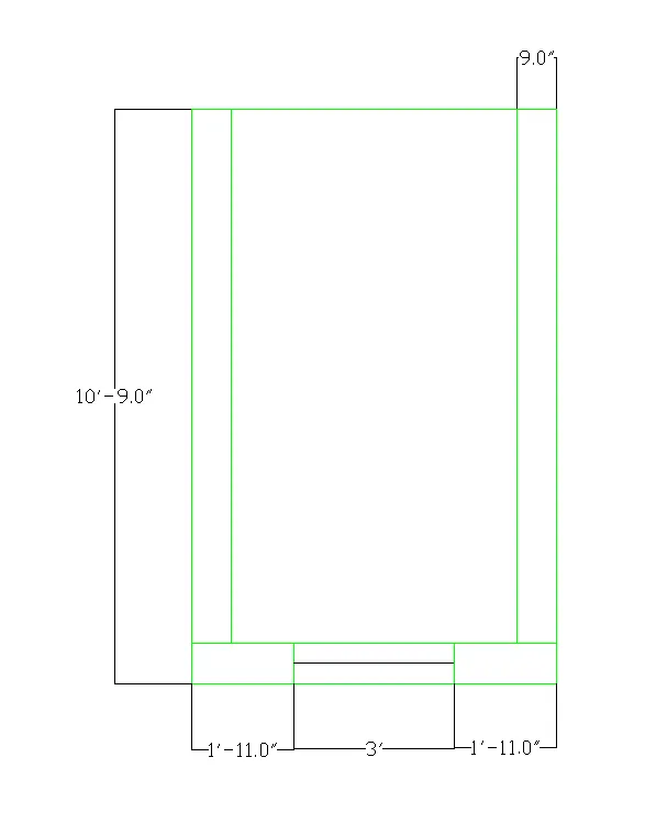
Draw window with dimensions: 3' x 9" units
Draw the given plan
Set the VIEW CONTROL to FRONT
Type LAYERS
Create New Layer: 2D-Elevation
Assign Colour to the Layer.
Draw the Elevations under the created Layer.
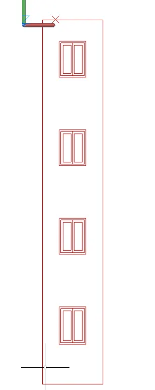
Type LINE
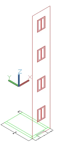
Draw the Elevation as shown in figure.
Set the VIEW CONTROL to SW ISOMETRIC
Type ALIGN
Select objects to align
Choose 1st Source point as point on Elevation
Choose 1st destination point as point on plan
Choose 2nd Source point as point on Elevation
Choose 2nd destination point as point on plan.
Press Enter.
Type LAYERS
Create New Layer: 3D-WALLS
Assign Colour to the Layer.
Set the current Layer as 3D-WALLS
Type BOUNDARY
Object Type: Region
Pick points as the internal points on the WALLS.
Press Enter
Type LINE
Draw Rectangle over the windows under 3D-WALLS Layer.
Copy the Rectangles to the wall Height.
Press Enter.
Type EXTRUDE
Select the WALLS
Enter the Height for Extrusion: 4’6” units.
Type EXTRUDE
Select the walls over windows.
Enter the Height for Extrusion: 4’6” units.
Extrude walls over windows till Sill Level from Bottom
Press Enter
Type UNION
Select all the 3D-WALLS drawn
Press Enter
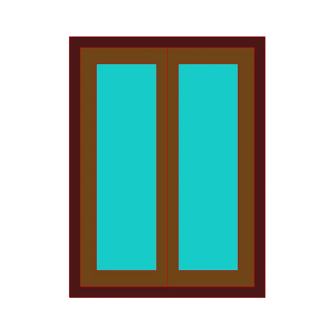
Create the Window from Elevation of size 3' x 4'2" units.
Type LAYERS
Create New Layer: 3D-Window Frame
Assign Colour to the Layer
Create New Layer: 3D-Window Mullion
Assign Colour to the Layer
Create New Layer: 3D-Window Glass
Assign Colour to the Layer.
Select the 3D-Window Frame as Current Layer
Type BOUNDARY
Object Type: Region
Pick points as the internal points on the Window.
Press Enter
Type SUBTRACT
Select the Outer panel of window
Press Enter
Select the Inner panels of window to subtract
Press Enter
Type SUBTRACT
Select the 2nd panel of window
Press Enter
Select the Inner panel of window to subtract
Press Enter
Type SOLIDEDIT
Enter a Solid Editing option: FACE
Select Extrude option
Select faces of the WALLS to extrude.
Specify Height of extrusion: 4’2” units.
Specify angle of taper for Extrusion: 0
Press Enter
Extrude all the WALLS.
Type LINE
Draw Rectangle over the windows under 3D-WALLS Layer.
Press Enter.
Type BOUNDARY
Object Type: Region
Pick points as the internal points on the Window.
Press Enter
Type EXTRUDE
Select the Rectangle over windows.
Enter the Height for Extrusion: 5’11” units.
Extrude walls over windows
Press Enter
Type SOLIDEDIT
Enter a Solid Editing option: FACE
Select Extrude option
Select faces of the WALLS to extrude.
Specify Height of extrusion: 5’11” units.
Specify angle of taper for Extrusion: 0
Press Enter
Extrude all the WALLS.
Type MOVE
Select all the Window panels
Select the Base Point
Specify the next point: @0,4”,0
Press Enter
Select the 3D-Window Frame as Current Layer
Create the 2nd Window of size 3’ x 4’ units from Elevation for the 2nd floor.
Type BOUNDARY
Object Type: Region
Pick points as the internal points on the Window.
Press Enter
Type SUBTRACT
Select the Outer panel of window
Press Enter
Select the Inner panels of window to subtract
Press Enter
Type SUBTRACT
Select the 2nd panel of window
Press Enter
Select the Inner panel of window to subtract
Press Enter
Type SOLIDEDIT
Enter a Solid Editing option: FACE
Select Extrude option
Select faces of the WALLS to extrude.
Specify Height of extrusion: 5'11" units.
Specify angle of taper for Extrusion: 0
Press Enter
Extrude all the WALLS.
Type MOVE
Select all the Window panels
Select the Base Point
Specify the next point: @0,4”,0
Press Enter
Type COPY
Select all the WINDOW PANELS of size 3’ x 4’ units.
Select base point.
Specify displacement: @0,0,9’11”
Press Enter
Type LINE
Draw Rectangle over the windows under 3D-WALLS Layer.
Press Enter.
Type BOUNDARY
Object Type: Region
Pick points as the internal points on the Window.
Press Enter
Type EXTRUDE
Select the Rectangle over windows.
Enter the Height for Extrusion: 5’11” units.
Extrude walls over windows
Press Enter
Type SOLIDEDIT
Enter a Solid Editing option: FACE
Select Extrude option
Select faces of the WALLS to extrude.
Specify Height of extrusion: 9’11” units.
Specify angle of taper for Extrusion: 0
Press Enter
Extrude all the WALLS.
Type COPY
Select all the WINDOW PANELS of size 3’ x 4’ units. from 2nd floor
Select base point.
Specify displacement: @0,0,9’11”
Press Enter.
Type LINE
Draw Rectangle over the windows under 3D-WALLS Layer.
Press Enter.
Type BOUNDARY
Object Type: Region
Pick points as the internal points on the Window.
Press Enter
Type EXTRUDE
Select the Rectangle over windows.
Enter the Height for Extrusion: 2’5” units.
Extrude walls over windows
Press Enter
Type SOLIDEDIT
Enter a Solid Editing option: FACE
Select Extrude option
Select faces of the WALLS to extrude.
Specify Height of extrusion: 6'5” units.
Specify angle of taper for Extrusion: 0
Press Enter
Extrude all the WALLS.
Type LINE
Specify 1st point: select outer edge of the building.
Specify next point: @0,0,6,5”
Specify next point: @6’9”,0,0
Specify next point: @0,0,-6’5”
Press Enter
Type JOIN
Select the lines drawn.
Press Enter.
Type RECTANG
Draw Rectangle of size 4” x 9” units.
Press Enter
Type SWEEP
Select the object as Rectangle 4” x 9”
Select the path
Choose the base line.
Press Enter
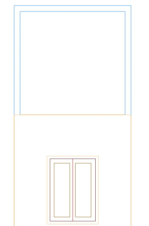
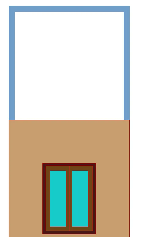
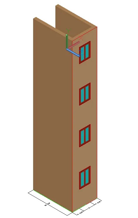
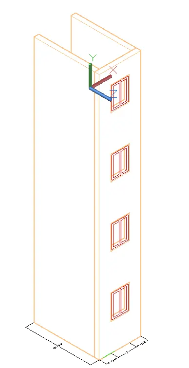
RESULT: -
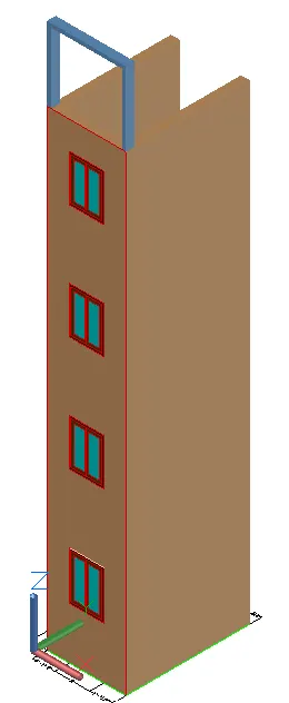
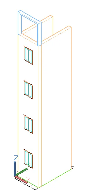
We created the 3D view of the building Facade.
3Q]
AIM: -
Create 3D Isometric View of the STAIRCASE with RAILING.
Use 3D modelling commands to draw the 3D model.
PROCEDURE: -
Start the AutoCAD with units as IMPERIAL
Set the Units to ENGINEERING
In RIBBON, got to VIEW palette.
In VIEW, go to Viewport tools and turn on the UCS icon, NAVIGATION bar, and VIEW CUBE
Switch the Workspace to 3D MODELLING
Set the VIEW CONTROL to TOP
Type LAYERS
Create New Layer: 2D-Floor Plan
Assign Colour to the Layer.
Draw the Floor Plan under the created Layer.
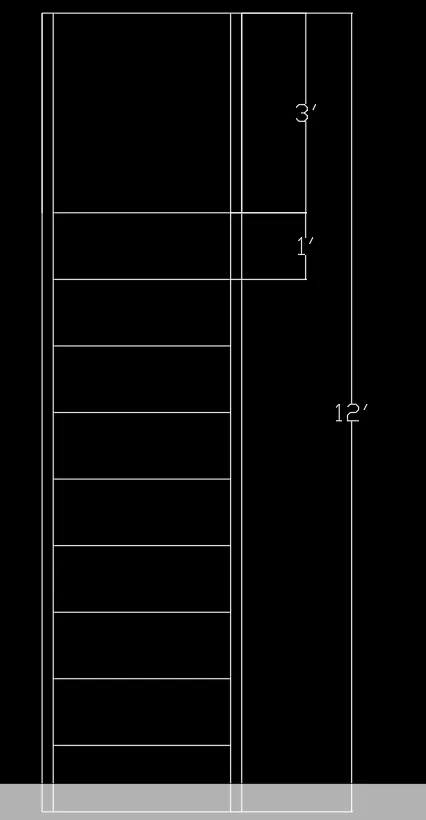
Type LINE
Specify 1st point: 0,0
Specify next point: 0,12'
Specify next point: @3',0
Specify next point: @0,-12'
Press Enter
Type OFFSET
Specify offset distance :3'
Select the 3' units line
Press enter
Repaet the OFFSET command with offset distance as 1' units till we reach at the end.
Draw the given plan
Set the VIEW CONTROL to RIGHT
Type LAYERS
Create New Layer: 2D-Elevation
Assign Colour to the Layer.
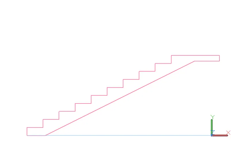
Draw the Elevations under the created Layer.
Type LINE
Draw the Elevation as shown in the figure.
Set the VIEW CONTROL to SE ISOMETRIC
Type ALIGN
Select objects to align
Choose 1st Source point as point on Elevation
Choose 1st destination point as point on plan
Choose 2nd Source point as point on Elevation
Choose 2nd destination point as point on plan.
Press Enter.
Type LAYERS
Create New Layer: 3D-STAIRCASE
Assign Colour to the Layer.
Set the current Layer as 3D-STAIRCASE
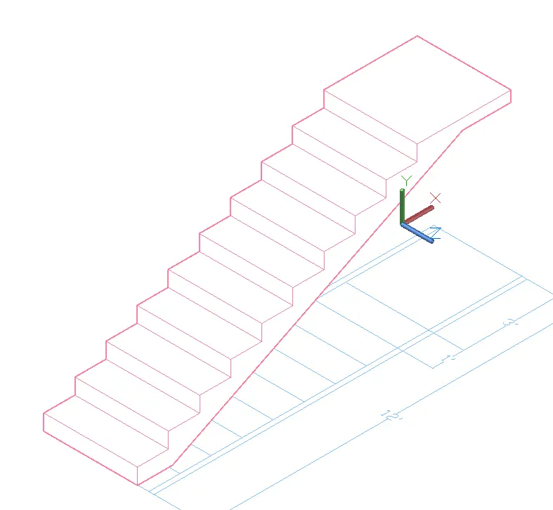
Type BOUNDARY
Object Type: Region
Pick points as the internal points on the STAIRS.
Press Enter
Type EXTRUDE
Select the STAIRS.
Enter the Height for Extrusion: -3’ units. in Z-axis.
Press Enter
Type LAYERS
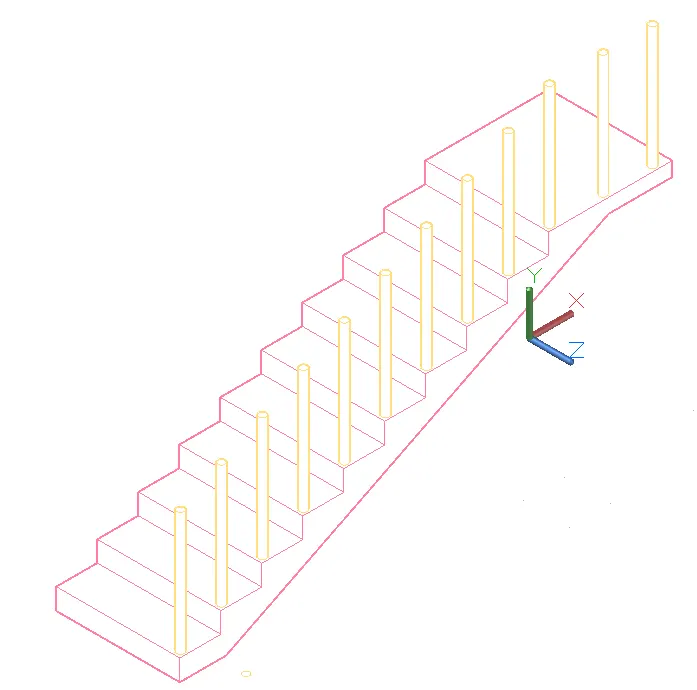
Create New Layer: 3D-BALUSTRADES
Assign Colour to the Layer.
Set the current Layer as 3D-BALUSTRADES.
Set the VIEW CONTROL to TOP
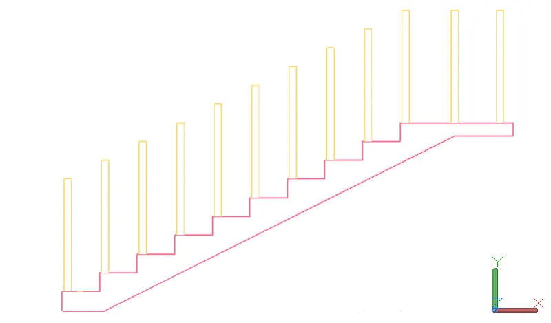
Type Circle
Select centre, diameter option
Specify diameter: 1” units.
Press Enter
Type BOUNDARY
Object Type: Region
Pick points as the internal points on the circle.
Press Enter
Set the VIEW CONTROL to SE ISOMETRIC
Type EXTRUDE
Select the STAIRS.
Enter the Height for Extrusion: 3’ units. in Y axis
Press Enter
Type COPY
Select the Balustrade
Specify the base point: corner of the step.
Place the balustrade on all steps.
Press Enter.
Type LAYERS
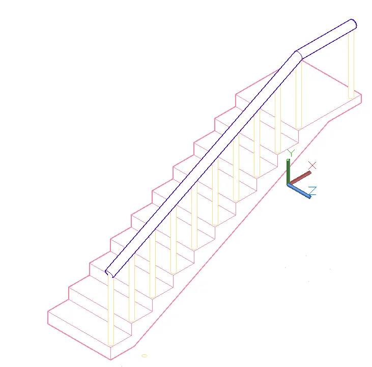
Create New Layer: 3D-RAILING.
Assign Colour to the Layer.
Set the current Layer as 3D-RAILING.
Type LINE
Select centre of the Balustrade and draw the passing through the centres of the balustrades.
Press Enter.
Type Circle
Select centre, diameter option
Specify diameter: 2” units.
Press Enter
Type SWEEP
Select the object as circle
Select the path as the Line drawn through the centres of balustrades.
Press Enter
RESULT: -
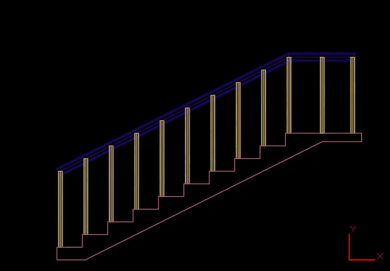
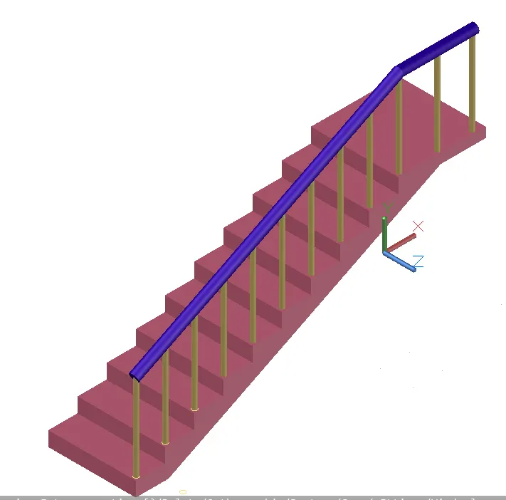
We created the 3D-view of the STAIRS WITH RAILING.
4Q]
AIM: -
Create the 3D view of the WALL with Spread Footing.
Apply materials to the model.
Create a Rendered View of the model.
PROCEDURE: -
Start the AutoCAD with units as METRIC
Set the Units to DECIMAL
In RIBBON, got to VIEW palette.
In VIEW, go to Viewport tools and turn on the UCS icon, NAVIGATION bar, and VIEW CUBE
Switch the Workspace to 3D MODELLING
Set the VIEW CONTROL to TOP
Type LAYERS
Create New Layer: 2D-Floor Plan
Assign Colour to the Layer.
Draw the Floor Plan under the created Layer.
Type LINE
Draw line of length 7500 units.
Select OFFSET command and provide distance 230 units and select the line.
Select OFFSET command and provide distance 100 units and select the line.
Repeat this on both sides of the wall.
Draw Door with width of 900 units at a distance of 3300 units
Draw the given plan
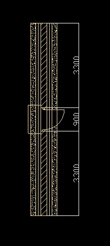
Set the VIEW CONTROL to FRONT
Type LAYERS
Create New Layer: 2D-Elevation
Assign Colour to the Layer.
Draw the Elevations under the created Layer.
Type LINE
Draw the Elevation as shown in the figure.
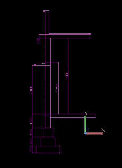
Set the VIEW CONTROL to SW ISOMETRIC
Type ALIGN
Select objects to align
Choose 1st Source point as point on Elevation
Choose 1st destination point as point on plan
Choose 2nd Source point as point on Elevation
Choose 2nd destination point as point on plan.
Press Enter.
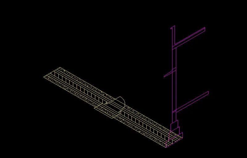
Type LAYERS
Create New Layer: 3D-FOOTING
Assign Colour to the Layer.
Set the current Layer as 3D-FOOTING
Type BOUNDARY
Object Type: Region
Pick points as the internal points on the FOOTING.
Press Enter
Type EXTRUDE
Select the FOOTING.
Enter the Height for Extrusion: 7500 units. in X-axis.
Press Enter
Type LAYERS
Create New Layer: 3D-SF1
Assign Colour to the Layer.
Set the current Layer as 3D-SF1.
Type BOUNDARY
Object Type: Region
Pick points as the internal points on the SF1.
Press Enter
Type EXTRUDE
Select the FOOTING.
Enter the Height for Extrusion: 7500 units. in X-axis.
Press Enter
Type LAYERS
Create New Layer: 3D-SF2
Assign Colour to the Layer.
Set the current Layer as 3D-SF2.
Type BOUNDARY
Object Type: Region
Pick points as the internal points on the SF2.
Press Enter
Type EXTRUDE
Select the SF2.
Enter the Height for Extrusion: 7500 units. in X-axis.
Press Enter
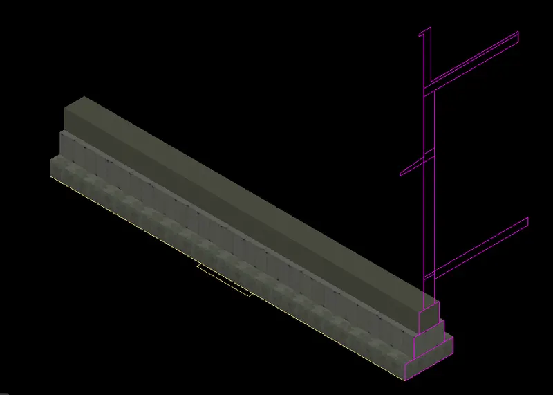
Type LAYERS
Create New Layer: 3D-WALL
Assign Colour to the Layer.
Set the current Layer as 3D-WALL.
Type BOUNDARY
Object Type: Region
Pick points as the internal points on the WALL.
Press Enter
Type EXTRUDE
Select the WALL.
Enter the Height for Extrusion: 7500 units. in X-axis.
Press Enter.
Turn off all the LAYERS except FLOOR PLAN.
Set the VIEW CONTROL to TOP
Set the Visual style to 2D WIREFRAME
Type LINE
Draw Rectangle of size 900 x 230 units over the Door
Press ENTER.
Turn on the SF2 Layer
Move the Rectangle fom bottom of footing to 1550 units in Y-axis..
Type EXTRUDE
Select the Rectangle.
Enter the Height for Extrusion: 2250 units. in Y-axis.
Press Enter.
Type SUBTRACT
Select object as the WALL
Press Enter
Select the object as Rectangle.
Press Enter.
Area is created for the Door and lintel.
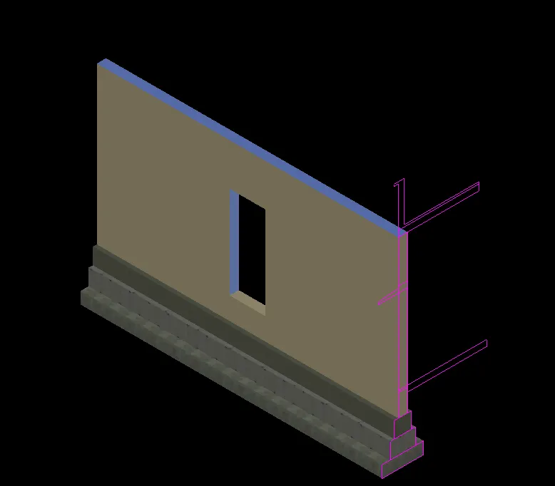
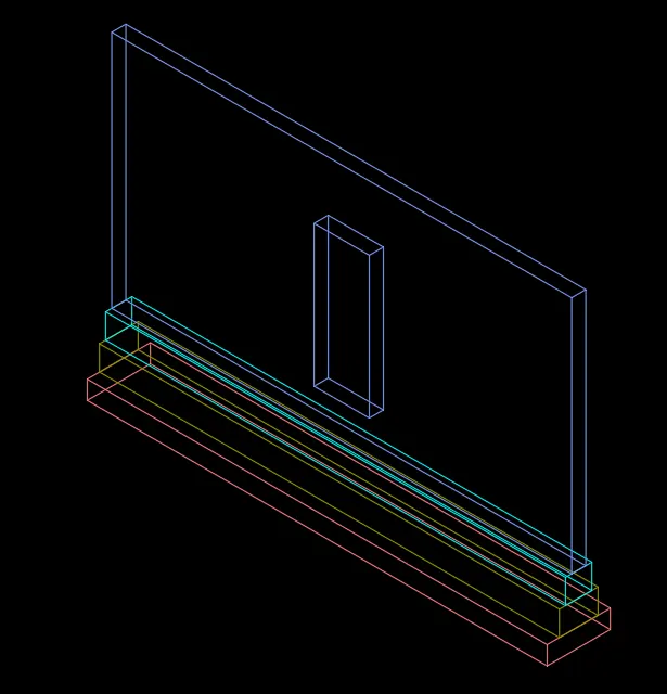
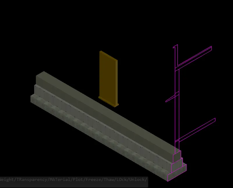
Type LINE
Draw Rectangle of size 900 x 230 units over the Door
Press ENTER.
Type LAYERS
Create New Layer: 3D-LINTEL
Assign Colour to the Layer.
Set the current Layer as 3D-LINTEL.
Type BOUNDARY
Object Type: Region
Pick points as the internal points on the LINTEL.
Press Enter
Type EXTRUDE
Select the lintel.
Enter the Height for Extrusion: 150 units. in Y-axis.
Press Enter.
Set the VIEW CONTROL to FRONT
Type LINE
Draw SHADES over the Door from the 2D-Elevation.
Press ENTER.
Type LAYERS
Create New Layer: 3D-SHADES
Assign Colour to the Layer.
Set the current Layer as 3D-SHADES.
Type BOUNDARY
Object Type: Region
Pick points as the internal points on the shades.
Press Enter
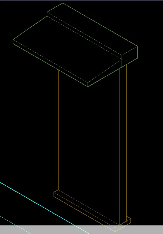
Type EXTRUDE
Select the lintel.
Enter the Height for Extrusion: 1100 units. in X-axis.
Press Enter.
CREATE FLOOR SLAB
Set the VIEW CONTROL to FRONT
Type LAYERS
Create New Layer: 3D-SLAB
Assign Colour to the Layer.
Set the current Layer as 3D-SLAB.
Type LINE
Draw Rectangle of thickness 150 units for SLAB from the Elevation drawing
Press ENTER.
Type BOUNDARY
Object Type: Region
Pick points as the internal points on the SLAB.
Press Enter
Type EXTRUDE
Select the SLAB.
Enter the Height for Extrusion: 7500 units. in X-axis.
Press Enter.
CREATE FLOORING ON ABOVE FLOOR SLAB
Set the VIEW CONTROL to FRONT
Type LAYERS
Create New Layer: 3D-FLOORING
Assign Colour to the Layer.
Set the current Layer as 3D-FLOORING.
Type LINE
Draw Rectangle of thickness 20 units above the SLAB from the Elevation drawing
Press ENTER.
Type BOUNDARY
Object Type: Region
Pick points as the internal points on the SLAB.
Press Enter
Type EXTRUDE
Select the flooring.
Enter the Height for Extrusion: 7500 units. in X-axis.
Press Enter.
CREATE ROOF SLAB
Set the VIEW CONTROL to FRONT
Type LINE
Draw Rectangle above the WALL from the Elevation drawing
Press ENTER.
Type BOUNDARY
Object Type: Region
Pick points as the internal points on the SLAB.
Press Enter
Type EXTRUDE
Select the SLAB.
Enter the Height for Extrusion: 7500 units. in X-axis.
Press Enter.
CRETAE FLOORING ON ABOVE ROOF SLAB
Type LINE
Draw Rectangle of thickness 20 units above the SLAB from the Elevation drawing
Press ENTER.
Type BOUNDARY
Object Type: Region
Pick points as the internal points on the SLAB.
Press Enter
Type EXTRUDE
Select the flooring.
Enter the Height for Extrusion: 7500 units. in X-axis.
Press Enter.
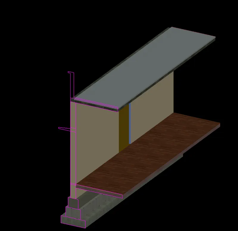
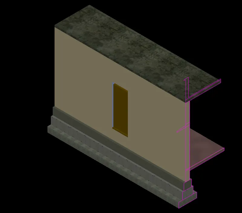
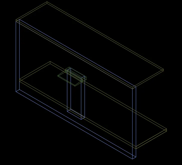
Set the VIEW CONTROL to FRONT
Type LAYERS
Create New Layer: 3D-PARAPET WALL
Assign Colour to the Layer.
Set the current Layer as 3D-PARAPET WALL.
Type LINE
Draw the wall as shown in the Elevation drawing
Press ENTER.
Type BOUNDARY
Object Type: Region
Pick points as the internal points on the Parapet wall.
Press Enter
Set the VIEW CONTROL to SW-ISOMETRIC
Type EXTRUDE
Select the PARAPET WALL.
Enter the Height for Extrusion: 7500 units. in X-axis.
Press Enter.
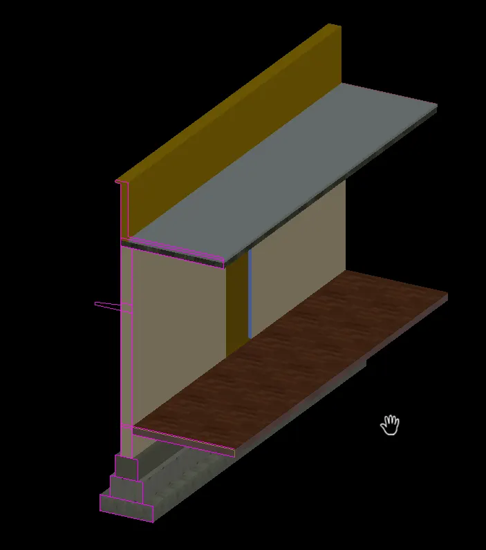
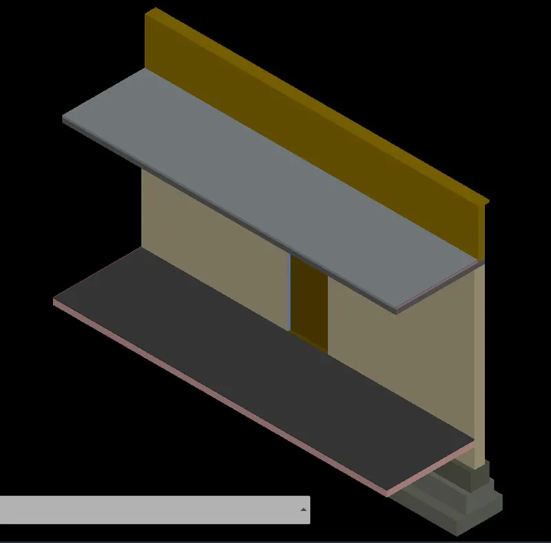
Type RMAT
Go to Autodesk Library
Select Concrete and choose one of the types and add material to document.
Select Footing and assign the material to the object.
Press Enter
Type RMAT
Go to Autodesk Library
Select Concrete and choose one of the types and add material to document.
Select and assign the material to the object.
Press Enter
Type RMAT
Go to Autodesk Library
Select Concrete and choose one of the types and add material to document.
Select SF2 and assign the material to the object.
Press Enter
Type RMAT
Go to Autodesk Library
Select WALL PAITING and choose one of the types and add material to document.
Select WALL and assign the material to the object.
Press Enter
Type RMAT
Go to Autodesk Library
Select WOOD and choose one of the types and add material to document.
Select DOOR and assign the material to the object.
Press Enter
Type RMAT
Go to Autodesk Library
Select WALL PAINTING and choose one of the types and add material to document.
Select SHADES and assign the material to the object.
Press Enter
Type RMAT
Go to Autodesk Library
Select WALL PAITING and choose one of the types and add material to document.
Select PARAPET WALL and assign the material to the object.
Press Enter
Type RMAT
Go to Autodesk Library
Select Concrete and choose one of the types and add material to document.
Select SLABS and assign the material to the object.
Press Enter
Type RMAT
Go to Autodesk Library
Select FLOORING and choose one of the types and add material to document.
Select Floorings and assign the material to the object.
Press Enter
Set the Visual style to REALISTIC
Type RPREF
Render in: window
Choose Render Size:
Name: 4Q
Type RR
Save the file at required location.
RESULT: -
We created the 3D view of a WALL with Spread Footing.
We applied materials to the model.
We rendered the model after applying the materials.