Creating 3D Isometric view of various structural elements in AutoCAD
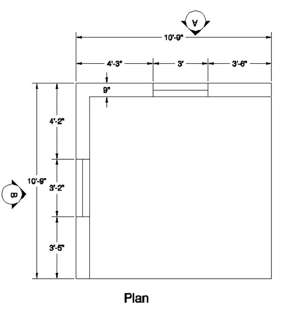
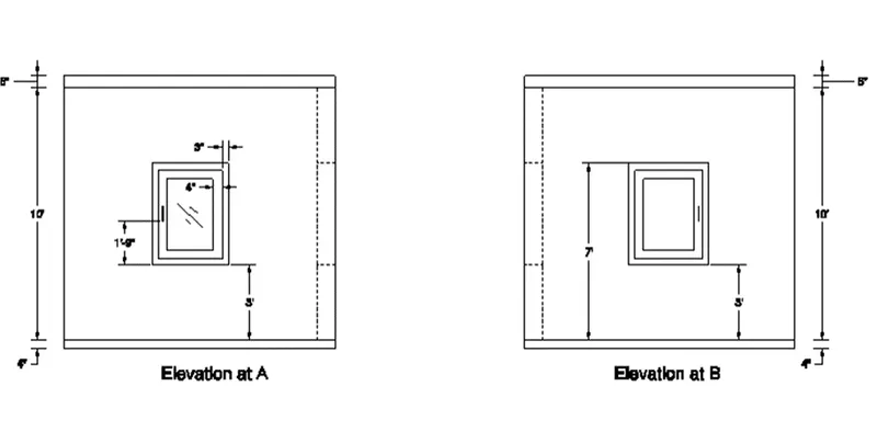
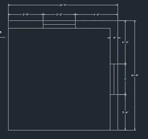
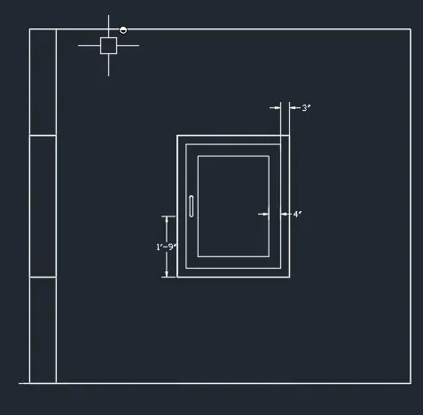
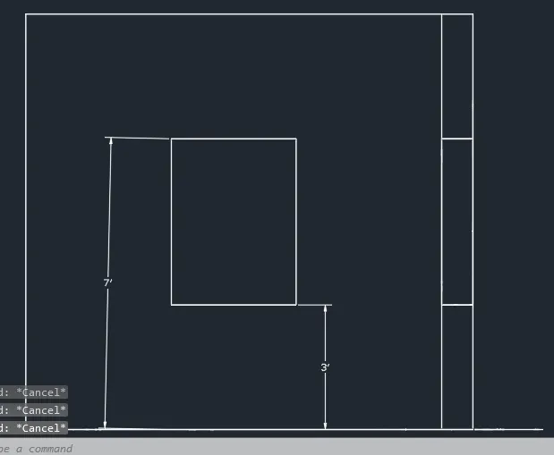
1. Create a 3D Isometric View of the building with the plan and elevation given.
AIM:
To create the 3D View of the Building Facade as given in the plan and elevation and create the window using the given dimensions
INTRODUCTION:
An isometric drawing is a 3D representation of an object, room, building or design on a 2D surface.
One of the defining characteristics of an isometric drawing, compared to other types of 3D representation, is that the final image is not distorted
This is because the foreshortening of the axes is equal.
In an isometric drawing, the object appears as if it is being viewed from above from one corner, with the axes being set out from this comer point.
Isometric drawings begin with one vertical line along which two points are defined.
PROCEDURE:
Select the line command and specify the first point and type 10'9" in the x-axis
Select the line and type 10'9" in the y-axis
Type offset and specify 9" and do the offset
Draw the window with the rectangle command of the specified length
Create a region using the REGION command
Extrude the walls by 10’
Draw the windows in the walls
Create region
Extrude the windows
Using the SUBTRACT command, subtract the window part from the walls
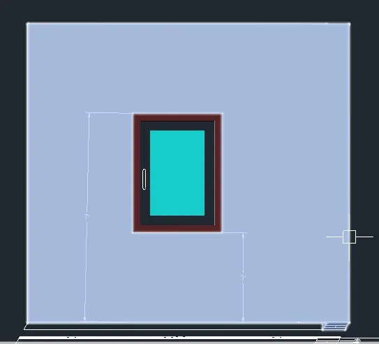
Select the Shade mode and see the drawing
RESULT
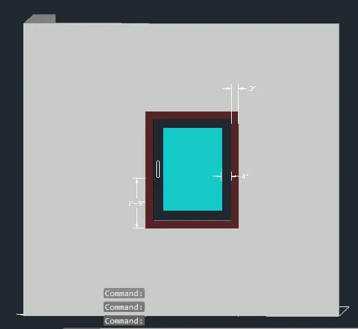
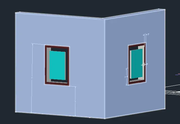
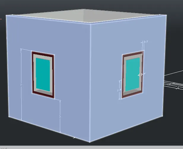
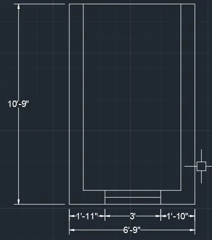
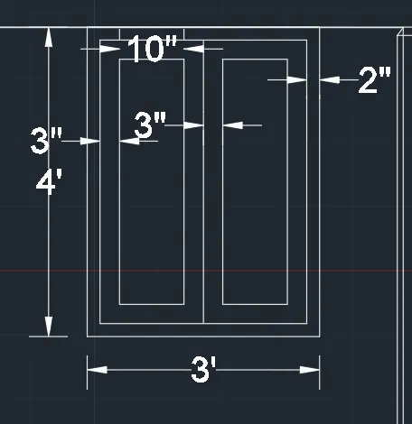
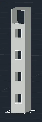
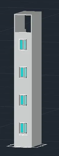
2. Create the 3D View of the Building Façade as given in the plan and elevation. Also, see the detail of the window.
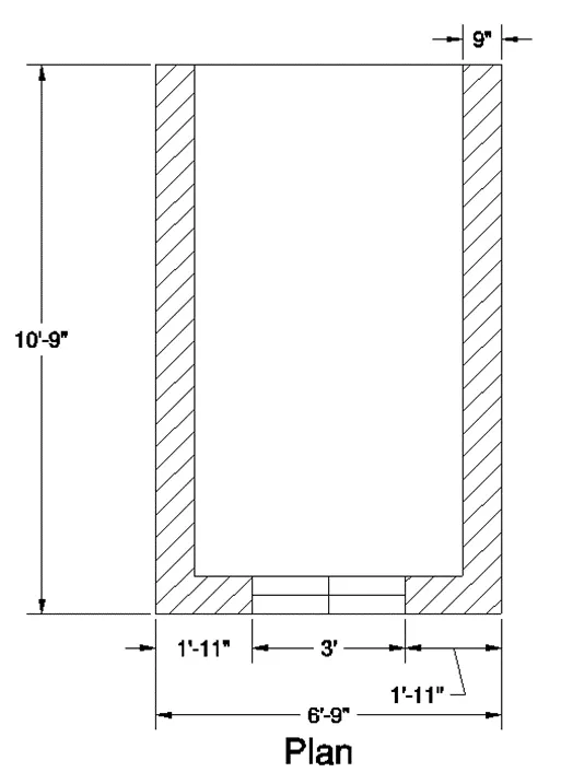
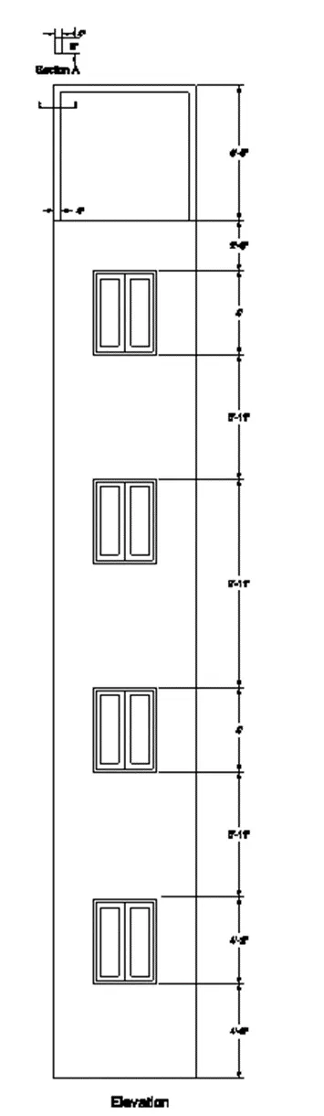
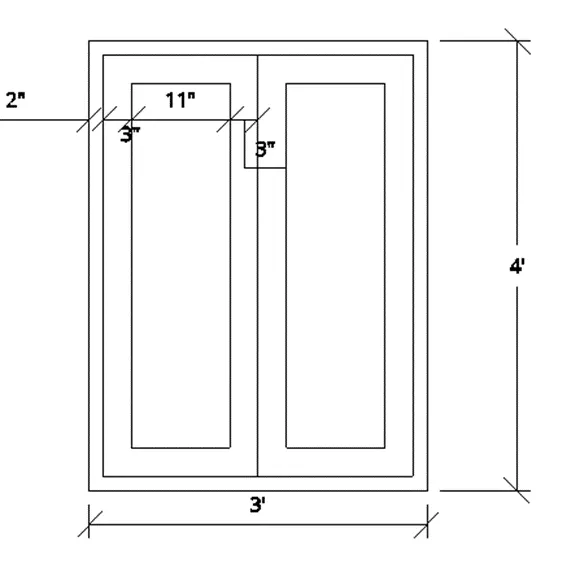
AIM
To create the 3D View of the Building Façade as given in the plan and elevation
PROCEDURE
Select the line command and specify the first point and type 10'9" in the x-axis
Select the line and type 6'9" in the y-axis
Type offset and specify 9" and do the offset
Draw the window with the rectangle command of the specified length
Create a region using the REGION command
Extrude the walls by
Draw the windows at appropriate locations in the wall
Create region
Extrude the windows
Using the SUBTRACT command, subtract the window part from the walls
Draw the detailing in the window using UCS, LINE, OFFSET and FILLET command
Create region
Using the SOLIDEDIT command colour the window
Select the Shade mode and see the drawing
RESULT
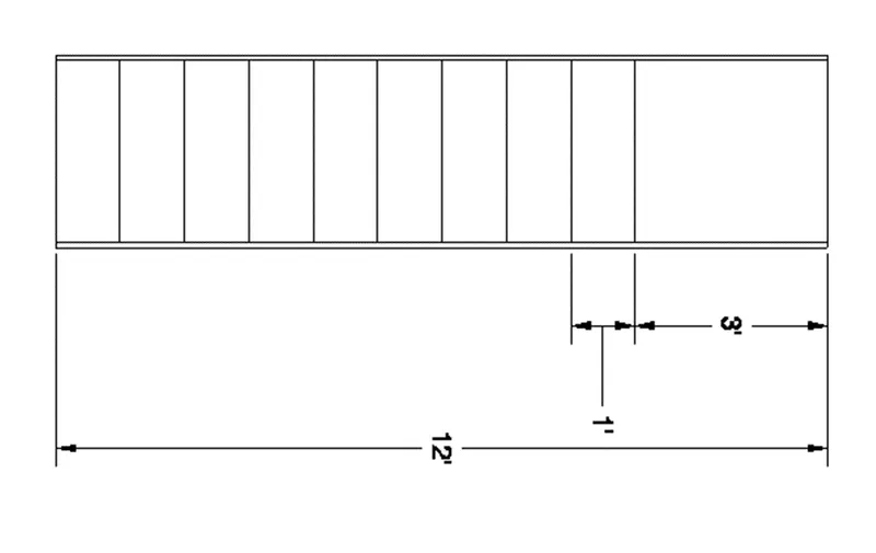
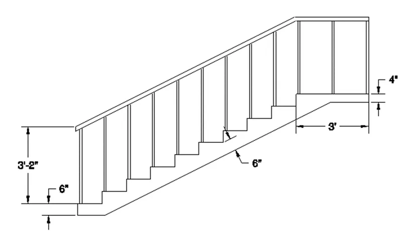
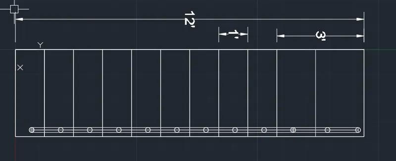
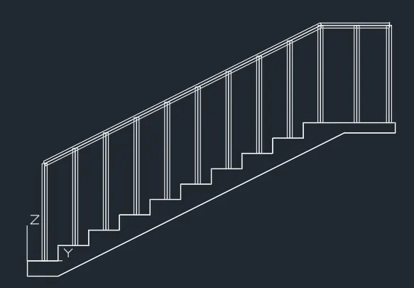
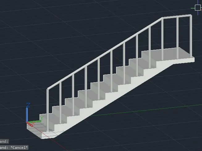
3. Create the isometric 3d view of a stair with a railing as shown in the plan and elevation. Assume the size of the balustrades and the handrails.
AIM
To create the isometric 3D view of a stair with a railing as shown in the plan and elevation.
PROCEDURE
Enter line command
Draw a 6” line in the z-direction
Draw a 12” line in x-direction
Copy these lines and paste them 10 times to make the stairs
Create boundary using BOUNDARY command
Extrude the stairs 3’
Draw a circle on the step
Create boundary using BOUNDARY command
Extrude the circle to create the railing
Copy and paste the railing to each step
Join the railings using 3DPOLYLINE
Create a circle
Using the SWEEP command, create the handrail
RESULT
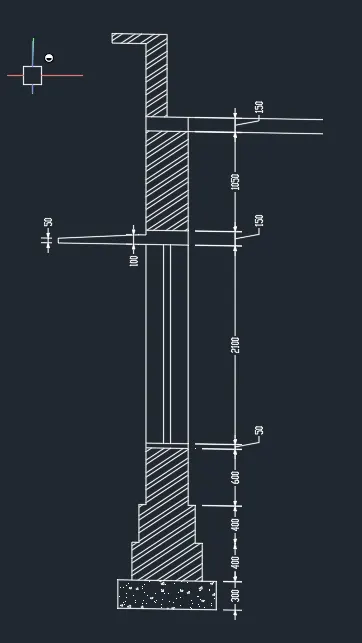
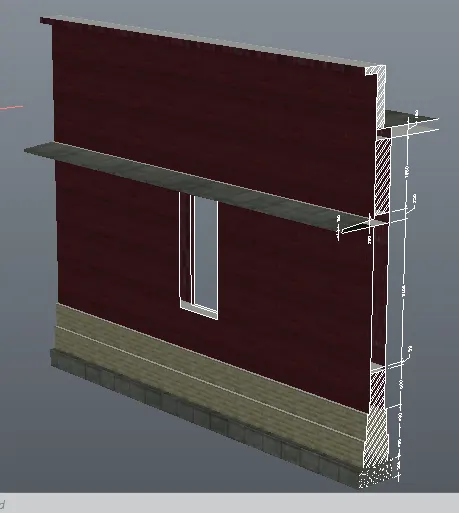
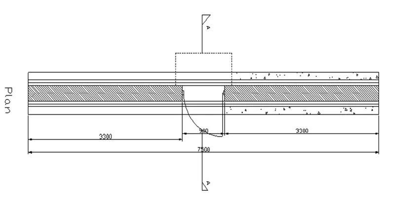
4. Create the 3D view of a Wall with spread footing. Create the Door opening only. Assume the size of the parapet and the coping. See the plans and elevation for the details. Also, create a rendered view of the model with materials of your choice.
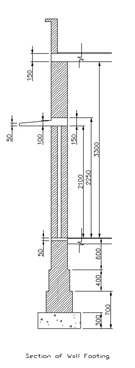
AIM
To create the 3D view of a Wall with spread footing. Create the Door opening only. Assume the size of the parapet and the coping. See the plans and elevation for the details. Also, create a rendered view of the model with materials of your choice.
PROCEDURE
Draw the elevation as given in the figure
Hatch the walls and footing using the HATCH command
Create a region of the whole wall
Extrude the wall using EXTRUDE command
Create the door in the wall
Trim the door using SUBTRACT command
Assign the material to each section accordingly
RESULT