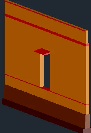
Creating 3D Isometric view of various structural elements in AutoCAD
Q.1. Create a 3D Isometric View of the building with plan and elevation given.
AIM:- To Draw the plan and creating it as a 3D elevation using Autocad.
Procedure:
1. Extrude- To give height to a surface or giving distance or height in z axis of an object in x y plane so that i become 3d.
2. Offset- To Draw the offset line. command "o"
3. UCS- command "USC" To change the usc so as to draw in that face ie. x and y plane will be made in the selected face so that it is easy to draw in that plane. Default is UCS world.
4. BOx- To create a box. it is found in the ome toolbar.
5. UNION- Command "union" To make different 3rd object into a single enitity.
6. Move- command "m"- To move an object in a particular axis . coordinate also can be given for moving an object after the command.
7. 3dorbit - command "3do" to rotate the object so that we can view around 360 degree.
8. Loft- Command " loft' is available in home toolbar. it is used to connect two section of an object.
9. Sweep - command-"sweep' or in home toolbar. it is used to created a 3d along a path created from the cross section.
11. Cone- it is an primitive object.
12. Region- command "region". it is used to create a region in a particular face so that it can be created to a solid while extruding.
13. Boundry - Command - "BO" from this command also region can be created.if the encircled region is created by different lines.
AIM: To create 3d isometric of a building with plan and elevation.
Step 1: Drawing the plan in the top view.
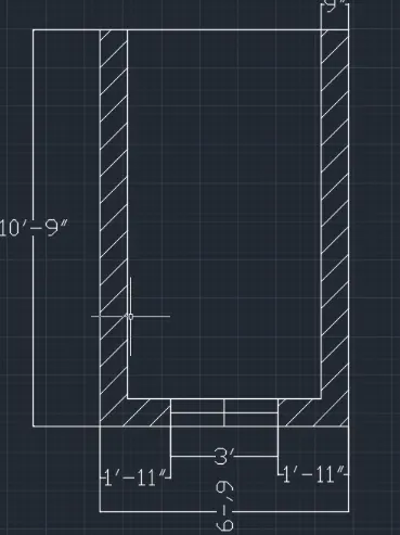
With line command a line of 10'9" vertically and horizotally such that a l- shap wall formed.
give offset of 4'2" from the corner of the wall.
Again give offset of 3'2" from that line for the window.
Step 2: Draw the window
Similary on the other side also , offset 4'3" from the corner 3' for the window.
Step 3: Making it 3d
Command "3do" for 3d ordit the view so that 3d is seen.
Now create a region in the wall area by command "BO" for boundary
Go to shaded view to see the boundary.
Now extrude the region giving a height of 10' command Extrude" give height 10'
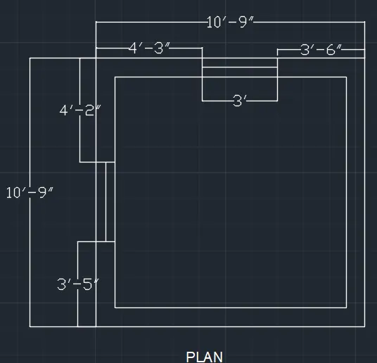
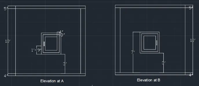
Result:-
The following drawing is obtained as plan.
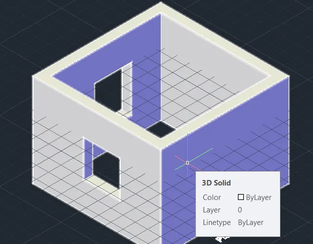
Q.2. Create the 3D View of the Building Façade as given in the plan and elevation. Also, see the detail of the window.
AIM:- Create a 3d view of building facade of plan and elevation with window details command used:
Procedure:
1. Extrude- To give height to a surface or giving distance or height in z axis of an object in x y plane so that i become 3d.
2. Offset- To Draw the offset line. command "o"
3. UCS- command "USC" To change the usc so as to draw in that face ie. x and y plane will be made in the selected face so that it is easy to draw in that plane. Default is UCS world.
4. BOx- To create a box. it is found in the ome toolbar.
5. UNION- Command "union" To make different 3rd object into a single enitity.
6. Move- command "m"- To move an object in a particular axis . coordinate also can be given for moving an object after the command.
7. 3dorbit - command "3do" to rotate the object so that we can view around 360 degree.
8. Loft- Command " loft' is available in home toolbar. it is used to connect two section of an object.
9. Sweep - command-"sweep' or in home toolbar. it is used to created a 3d along a path created from the cross section.
11. Cone- it is an primitive object.
12. Region- command "region". it is used to create a region in a particular face so that it can be created to a solid while extruding.
13. Boundry - Command - "BO" from this command also region can be created.if the encircled region is created by different lines.
- Type un command prompt and select engineering and precision to 0'-0'
- Type limits and specify lower and upper limits.
- z enter a centre.
- Type XL command prompt and then type v and draw the outer edge.
- Select the first point and draw a line horizontal
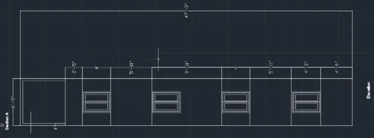
- Type offset and specify 6'5" and do the offset.
- Type offset and specify 4' and do the offset.
- Type offset and specify 5'11" and do the offset.
- Type offset and specify 9'11" and do the offset.
- Type offset and specify 4' and do the offset.
- Type offset and specify 5'11"and do the offset.
- Type offset and specify 4'2" and do the offset.
- Type offset and specify 4'6" and do the offset.
- Type offset and specify 4' and do the offset.
- Trim all the extra lines using trim command
- Type xl and draw construction lines with both ends of the window
- Trim the extra lines
Details of window:
- Select the plan and go to 3d home view.
- Type BO and create again
- Type SU in the command prompt and select the surface from where you have to substract the object enter
- Select the object to substract and then do the substraction
- Go to shaped portion from 2d wire frame
- Select the plan
- Go to home tab 0f 3d modelling
- Type BO and do the region of the elevation
- Select the extrude command and etrude the object
- select the window and type 3d rotate and select the base point and rotate the window paraller to the axis
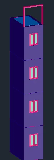
- the following drawing is obtained
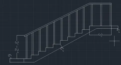
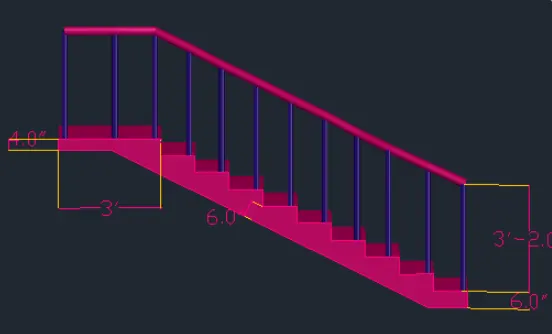
Q.3. Create the ismoteric 3d view of a stair with railing as shown in the plan and elevation. Assume the size of the balustrades and the hand rails.
AIM:- To Draw the plan and creating it as a 3D elevation using Autocad.
Procedure:
1. Extrude- To give height to a surface or giving distance or height in z axis of an object in x y plane so that i become 3d.
2. Offset- To Draw the offset line. command "o"
3. UCS- command "USC" To change the usc so as to draw in that face ie. x and y plane will be made in the selected face so that it is easy to draw in that plane. Default is UCS world.
4. BOx- To create a box. it is found in the ome toolbar.
5. UNION- Command "union" To make different 3rd object into a single enitity.
6. Move- command "m"- To move an object in a particular axis . coordinate also can be given for moving an object after the command.
7. 3dorbit - command "3do" to rotate the object so that we can view around 360 degree.
8. Loft- Command " loft' is available in home toolbar. it is used to connect two section of an object.
9. Sweep - command-"sweep' or in home toolbar. it is used to created a 3d along a path created from the cross section.
11. Cone- it is an primitive object.
12. Region- command "region". it is used to create a region in a particular face so that it can be created to a solid while extruding.
13. Boundry - Command - "BO" from this command also region can be created.if the encircled region is created by different lines.
- Type un command prompt and select engineering and precision to 0'-0'
- Type limits and specify lower and upper limits.
- z enter a centre.
- Type XL command prompt and then type v and draw the outer edge.
- Select the first point and draw a line horizontal
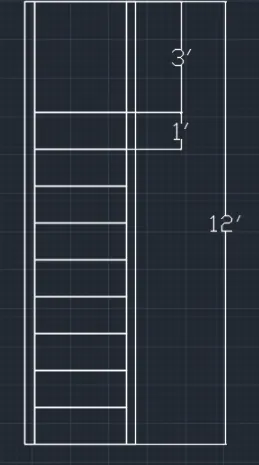
- type 3' and draw a line in the x direction
- Type 12' and draw a line in the y axis
- Type 3' and draw a line in x axis
- type 12' and draw a line in y axis
- Type offset and specify 3" and do the offset from both the side
- Type rec and select dimension and specify the dimension as 3' and 1"
- Type copy and select teh object and with the base point draw teh stairs as shown in fig.
- Pian is created.
- Trim all the extra lines using trim command
- Type xl and draw construction lines with both ends of the window
- Trim the extra lines
- Select the plan
- Go to home tab 0f 3d modelling
- Type BO and do the region of the elevation
- Select the extrude command and etrude the object
- select the window and type 3d rotate and select the base point and rotate the window paraller to the axis
- the following drawing is obtained
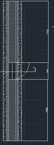
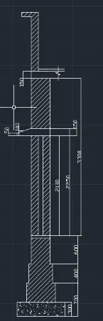
Q.4. Create the 3D view of a Wall with spread footing . Create the Door opening only. Assume the size of the parpaet and the coping. See the plans and elevation for the details. Also, create a rendered view of the model with materials as of your choice.
AIM:- To Draw the plan and creating it as a 3D elevation using Autocad.
Procedure:
1. Extrude- To give height to a surface or giving distance or height in z axis of an object in x y plane so that i become 3d.
2. Offset- To Draw the offset line. command "o"
3. UCS- command "USC" To change the usc so as to draw in that face ie. x and y plane will be made in the selected face so that it is easy to draw in that plane. Default is UCS world.
4. BOx- To create a box. it is found in the ome toolbar.
5. UNION- Command "union" To make different 3rd object into a single enitity.
6. Move- command "m"- To move an object in a particular axis . coordinate also can be given for moving an object after the command.
7. 3dorbit - command "3do" to rotate the object so that we can view around 360 degree.
8. Loft- Command " loft' is available in home toolbar. it is used to connect two section of an object.
9. Sweep - command-"sweep' or in home toolbar. it is used to created a 3d along a path created from the cross section.
11. Cone- it is an primitive object.
12. Region- command "region". it is used to create a region in a particular face so that it can be created to a solid while extruding.
13. Boundry - Command - "BO" from this command also region can be created.if the encircled region is created by different lines.
- Type un command prompt and select engineering and precision to 0'-0'
- Type limits and specify lower and upper limits.
- z enter a centre.
- Type XL command prompt and then type v and draw the outer edge.
- Select the first point and draw a line x direction
- type 7500 and draw a line in the y direction
- Type 1000 and draw a line in the x axis
- Type 7500 and draw a line in y axis
- Type offset and specify 200 and do the offset from both the side
- Type rec and select dimension and specify the dimension as 50 and 2 times.
- Type copy and select teh object and with the base point draw teh stairs as shown in fig.
- Pian is created.
- Trim all the extra lines using trim command
- Type xl and draw construction lines with both ends of the window
- Trim the extra lines
- Select the plan
- Go to home tab 0f 3d modelling
- Type BO and do the region of the elevation
- Select the extrude command and etrude the object
- select the window and type 3d rotate and select the base point and rotate the window paraller to the axis
- the following drawing is obtained