Creating 3D Isometric view of various structural elements in AutoCAD
Challenge 12: Creating 3D Isometric view of various structural elements in AutoCAD
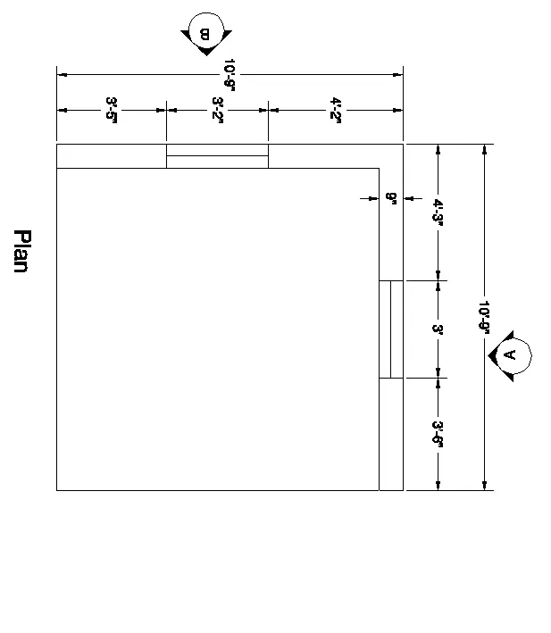
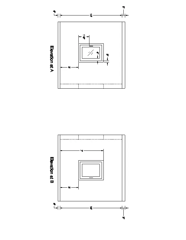
1. Create a 3D Isometric View of the building with plan and elevation given.
AIM
To create a 3D Isometric View of the building with plan and elevation given.
INTRODUCTION
3D modeling in AutoCAD includes 3D solids, surfaces, meshes, and wireframe objects. Several types of 3D modeling are available in AutoCAD.
PROCEDURE
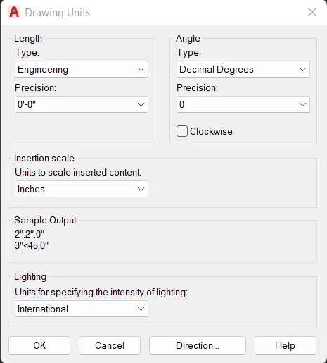
Open the AutoCAD Application and create a new AutoCAD file with imperial settings. Set the length type in 'Engineering' and precision (0'-0"), insertion scale to 'Inches' in the Drawing Units and press OK. Set limits and zoom all.
Click on 'Workspace Switching' and select '3D Modelling'
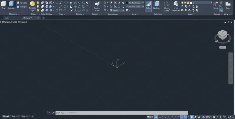
1. Draw the plan in xy plane
- Type 'PLAN' in the command line and enter
- Type 'REC' in the command line and enter to get rectangle
- Draw a rectangle of size 10'9"x10'9"
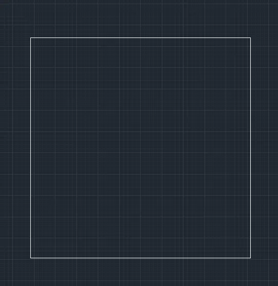
- Select the rectangle and type 'EXPLODE'
- Type 'OFFSET' in the command line and enter to get rectangle
- Offset 9" from the top and left line inwards
- Type 'TR' in the command line and enter to get trim tool
- Trim all unnecessary lines
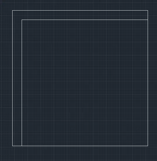
2. Draw the floor
- Type 'EXT' in the command line and enter to get extrude tool
- Select all objects and extrude 4" in the z direction
- Type 'HIDE' and enter
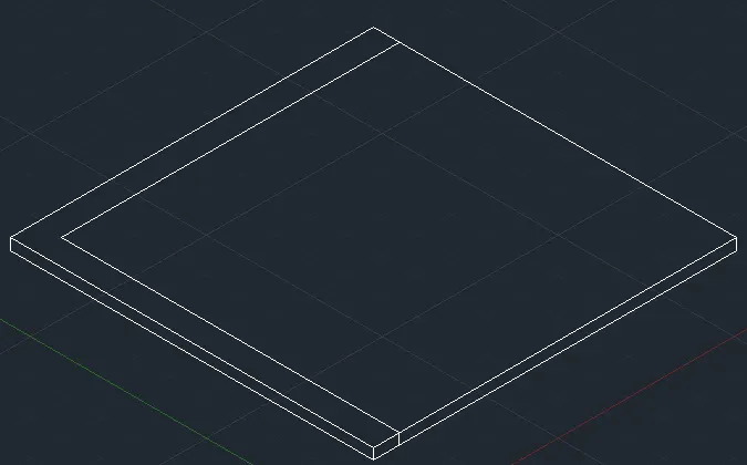
3. Draw the wall
- Type 'PRESSPULL' in the command line and enter to get presspull tool
- Select the top of 'L' shaped object and extrude 10' in the z direction
- Type 'HIDE' and enter
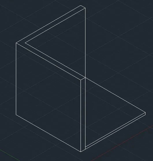
4. Draw the floor slab
- Type 'REC' in the command line and enter to get rectangle
- Draw a rectangle of size 10'9"x10'9" on top of the wall
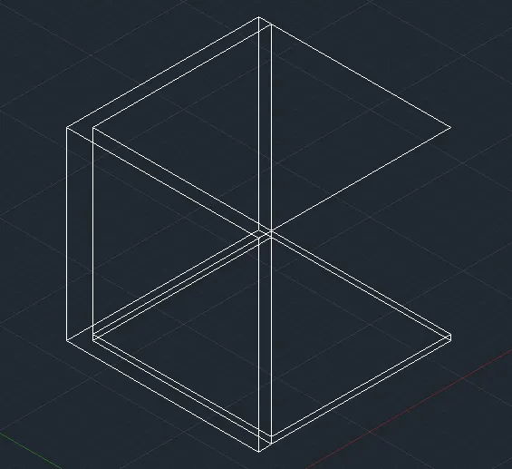
- Type 'EXT' in the command line and enter to get extrude tool
- Select the new rectangle and extrude 6" in the z direction
- Type 'HIDE' and enter
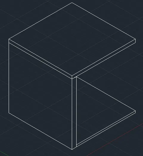
5. Draw the windows in the plane view
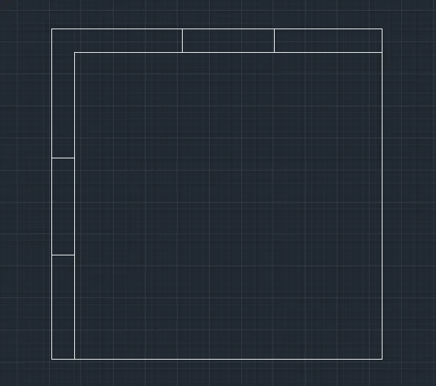
- Type 'REC' in the command line and enter to get rectangle
- Type 'TRA' and enter to get tracking mode
- Point the first tracking point as bottom left corner
- Type 3'5" in the y direction and enter
- Draw a rectangle of size 9"x3'2"
- Type 'TRA' and enter to get tracking mode
- Type 'REC' in the command line and enter to get rectangle
- Type 'TRA' and enter to get tracking mode
- Point the first tracking point as top left corner
- Type 4'3" in the x direction and enter
- Draw a rectangle of size 3'x9"
- Type 'TRA' and enter to get tracking mode
6. Create window hole in the 3D view
- Type '3DMOVE' in the command line and enter to get move tool
- Select the windows in the plan and move 3'4" in the z direction
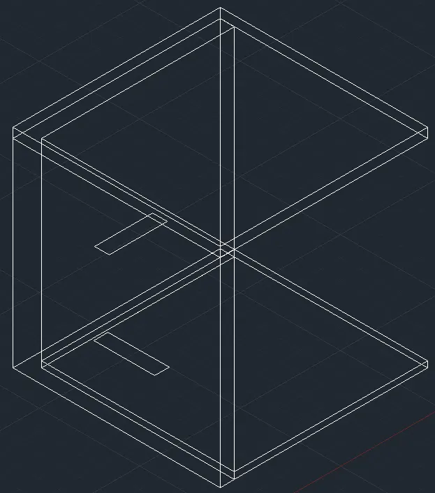
- Type 'EXT' in the command line and enter to get extrude tool
- Select the windows and extrude 4' in the z direction
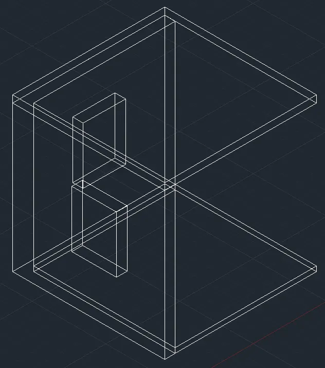
- Make the visual style to 'CONCEPTUAL'
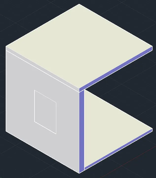
- Type 'SU' in the command line and enter to get subtract tool
- Select the wall and enter
- Select the windows and enter
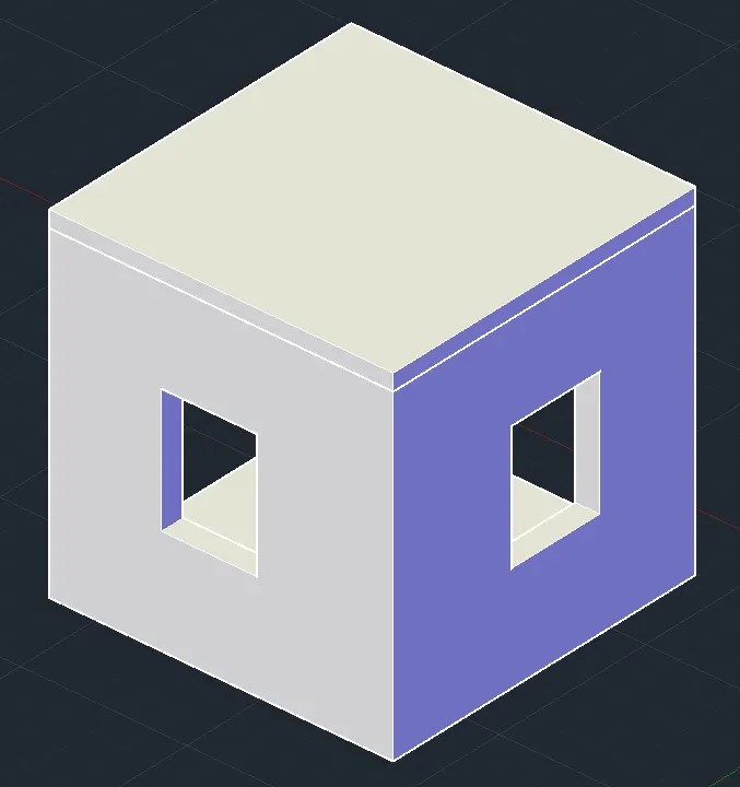
7. create 3D windows
a) 3'2" window
- Type 'REC' in the command line and enter to get rectangle
- Draw a rectangle of 3'2"x4'
- Type 'EXT' in the command line and enter to get extrude tool
- Select the new rectangle and extrude 4.5" in the z direction
- Type 'REC' in the command line and enter to get rectangle
- Draw a rectangle of 2'8"x3'6" inside center of the first rectangle
- Type 'EXT' in the command line and enter to get extrude tool
- Select the new rectangle and extrude 4.5" in the z direction
- Type 'SU' in the command line and enter to get subtract tool
- Select the first rectangle and enter
- Select the second rectangle and enter
- Type 'PR' in the command line and enter to get properties
- Select the window frame and change the color
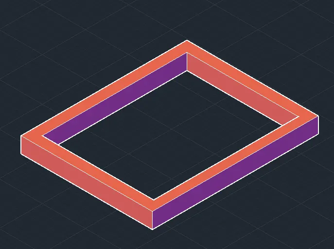
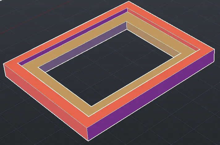
- Type 'REC' in the command line and enter to get rectangle
- Draw a rectangle of 2'8"x3'6" inside the window frame
- Type 'EXT' in the command line and enter to get extrude tool
- Select the new rectangle and extrude 3" in the z direction
- Type 'REC' in the command line and enter to get rectangle
- Draw a rectangle of 2'x2'10" inside center of the first rectangle
- Type 'EXT' in the command line and enter to get extrude tool
- Select the new rectangle and extrude 4.5" in the z direction
- Type 'SU' in the command line and enter to get subtract tool
- Select the first rectangle and enter
- Select the second rectangle and enter
- Type 'PR' in the command line and enter to get properties
- Select the inside window frame and change the color
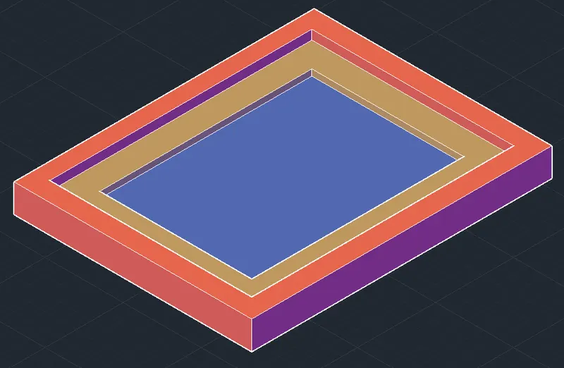
- Type 'REC' in the command line and enter to get rectangle
- Draw a rectangle of 2'x2'10" inside center of the second window frame
- Type 'EXT' in the command line and enter to get extrude tool
- Select the new rectangle and extrude 1" in the z direction
- Type 'M' in the command line and enter to get move tool
- Select the glass panel and paste it in the middle of the second frame
- Type 'PR' in the command line and enter to get properties
- Select the glass panel and change the color
b) 3' window
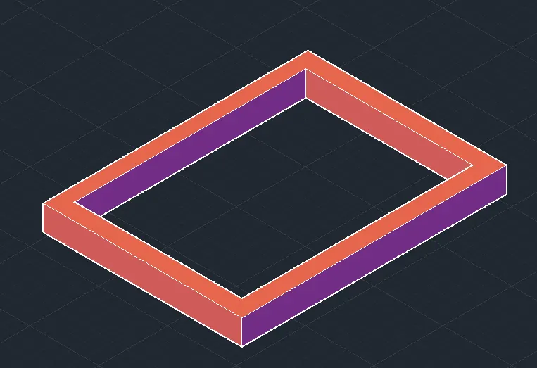
- Type 'REC' in the command line and enter to get rectangle
- Draw a rectangle of 3'x4'
- Type 'EXT' in the command line and enter to get extrude tool
- Select the new rectangle and extrude 4.5" in the z direction
- Type 'REC' in the command line and enter to get rectangle
- Draw a rectangle of 2'6"x3'6" inside center of the first rectangle
- Type 'EXT' in the command line and enter to get extrude tool
- Select the new rectangle and extrude 4.5" in the z direction
- Type 'SU' in the command line and enter to get subtract tool
- Select the first rectangle and enter
- Select the second rectangle and enter
- Type 'PR' in the command line and enter to get properties
- Select the window frame and change the color
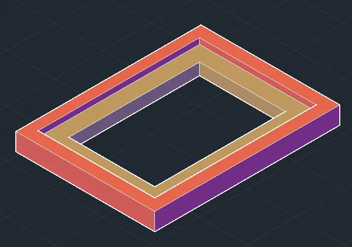
- Type 'REC' in the command line and enter to get rectangle
- Draw a rectangle of 2'6"x3'6" inside the window frame
- Type 'EXT' in the command line and enter to get extrude tool
- Select the new rectangle and extrude 3" in the z direction
- Type 'REC' in the command line and enter to get rectangle
- Draw a rectangle of 1'10"x2'10" inside center of the first rectangle
- Type 'EXT' in the command line and enter to get extrude tool
- Select the new rectangle and extrude 4.5" in the z direction
- Type 'SU' in the command line and enter to get subtract tool
- Select the first rectangle and enter
- Select the second rectangle and enter
- Type 'PR' in the command line and enter to get properties
- Select the inside window frame and change the color
- Type 'REC' in the command line and enter to get rectangle
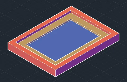
- Draw a rectangle of 1'10"x2'10" inside center of the second window frame
- Type 'EXT' in the command line and enter to get extrude tool
- Select the new rectangle and extrude 1" in the z direction
- Type 'M' in the command line and enter to get move tool
- Select the glass panel and paste it in the middle of the second frame
- Type 'PR' in the command line and enter to get properties
- Select the glass panel and change the color
8. Place the window in the window space
- Type '3DROTATE' in the command line and enter to get 3d rotate tool
- Select the windows and rotate it according to the design
- Type 'M' in the command line and enter to get move tool
- Select the windows and place it in the window space
- Type 'PR' in the command line and enter to get properties
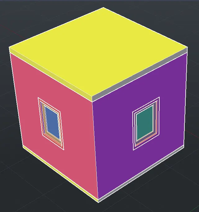
- Select the wall, floors and change the colors
RESULT
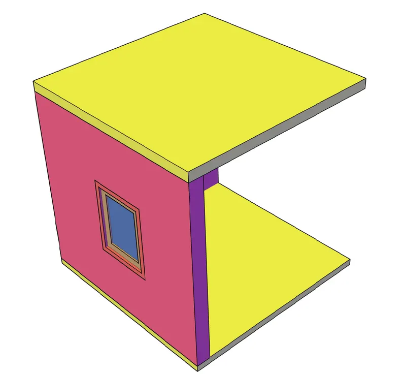
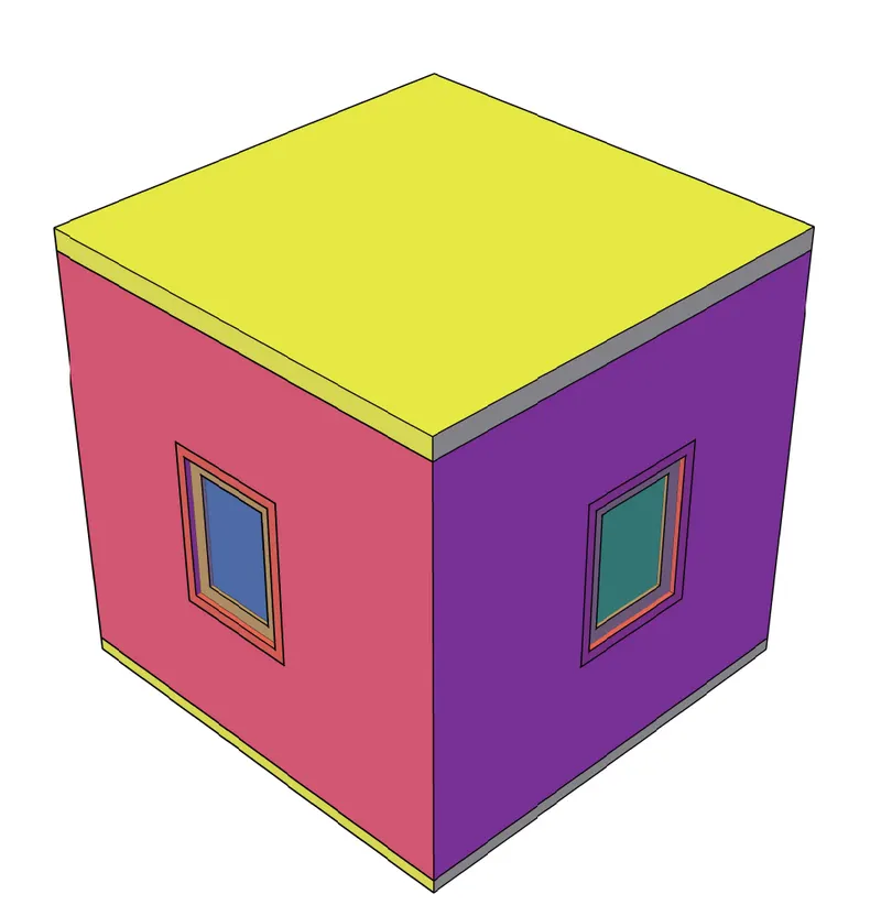
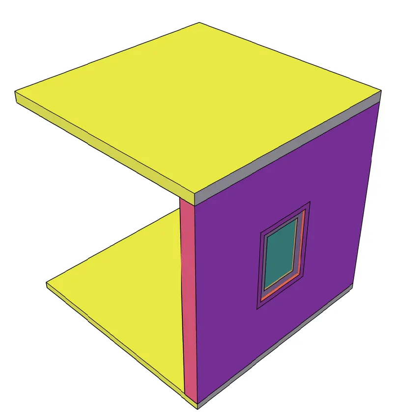
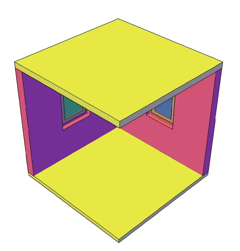
The 3D Isometric View of the building is created with the help of plan and elevation given. The different 3D isometric view of the building is shown below
a) S-W view
b) N-W view
c) N-W view
d) S-E view
2. Create the 3D View of the Building Façade as given in the plan and elevation. Also, see the detail of the window.
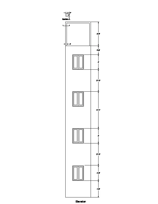
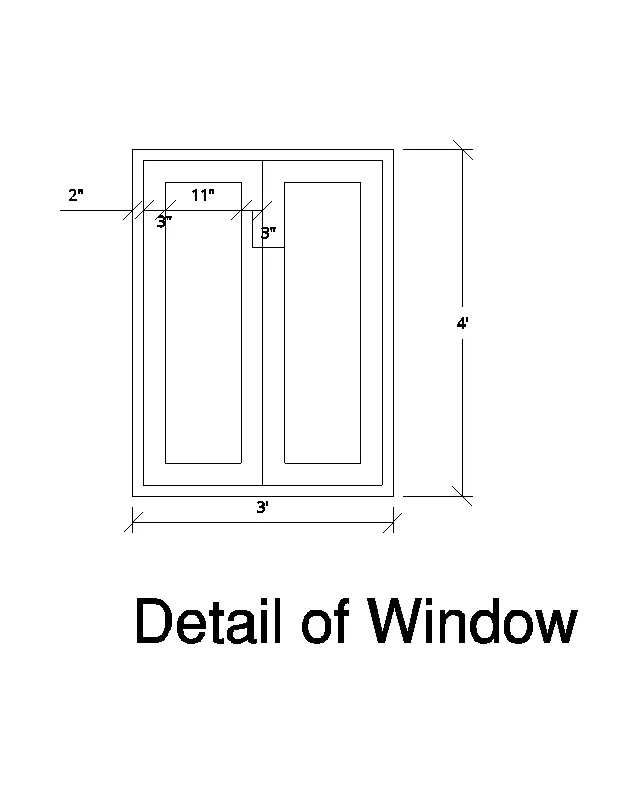
AIM
To create the 3D View of the Building Façade as given in the plan and elevation.
INTRODUCTION
3D modeling in AutoCAD includes 3D solids, surfaces, meshes, and wireframe objects. Several types of 3D modeling are available in AutoCAD.
PROCEDURE
Open the AutoCAD Application and create a new AutoCAD file with imperial settings. Set the length type in 'Engineering' and precision (0'-0"), insertion scale to 'Inches' in the Drawing Units and press OK. Set limits and zoom all.
Click on 'Workspace Switching' and select '3D Modelling'
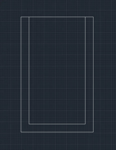
1. Draw the plan in xy plane
- Type 'PLAN' in the command line and enter
- Type 'REC' in the command line and enter to get rectangle
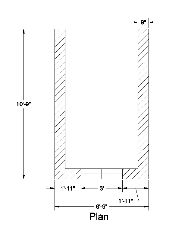
- Draw a rectangle of size 6'9"x10'9"
- Select the rectangle and type 'EXPLODE'
- Type 'OFFSET' in the command line and enter to get rectangle
- Offset 9" from the bottom, right and left line inwards
- Type 'TR' in the command line and enter to get trim tool
- Trim all unnecessary lines
2. Draw the wall upto windows top
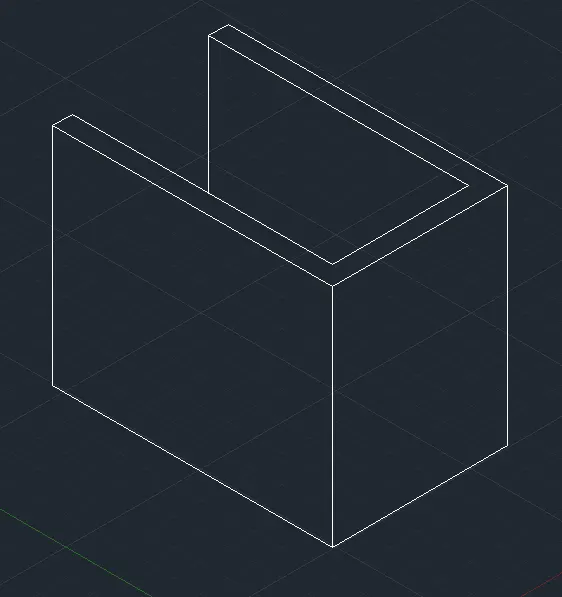
- Type 'EXT' in the command line and enter to get extrude tool
- Select the object and extrude 8'8" in the z direction
- Type 'HIDE' and enter
3. Create window hole in the 3D view
- Type 'REC' in the command line and enter to get rectangle
- Draw a rectangle of size 3'x4'2" and place it in the middle with 2" down of the outer wall
- Type 'HIDE' and enter
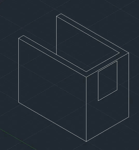
- Type 'EXT' in the command line and enter to get extrude tool
- Select the window and extrude 9" in the y direction
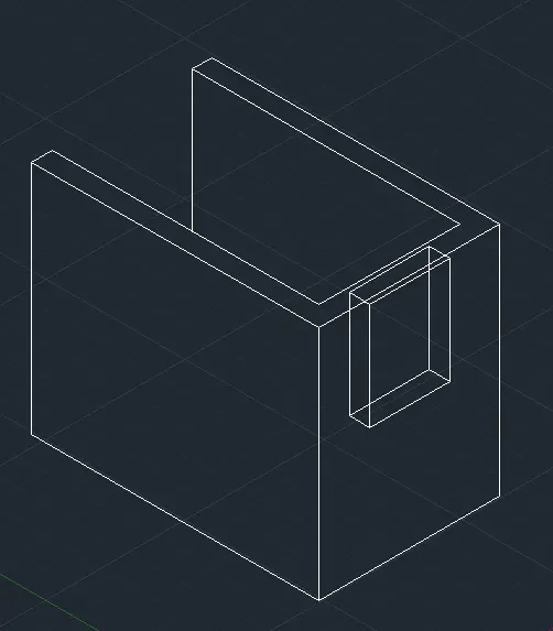
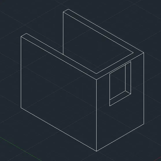
- Type 'SU' in the command line and enter to get subtract tool
- Select the wall and enter
- Select the windows and enter
- Type 'HIDE' and enter
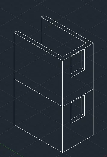
4. Create the upper floors
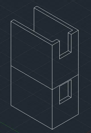
- Type 'CO' in the command line and enter to get copy tool
- Select all the objects and paste it above the ground floor
- Type 'HIDE' and enter
- Type 'PRESSPULL' in the command line and enter to get presspull tool
- Select the bottom of the window from 1st floor and presspull 1'5" in the z direction
- Select the top of the window from 1st floor and presspull 1'5" in the z direction
- Select the top of the wall from 1st floor and presspull 1'3" in the z direction
- Type 'HIDE' and enter
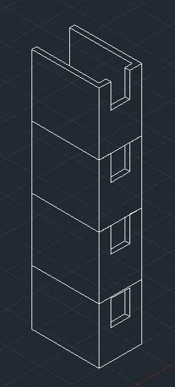
- Type 'CO' in the command line and enter to get copy tool
- Select all the 1st floor and paste it above the 1st floor
- Repeat the above step for 2 times
- Type 'HIDE' and enter
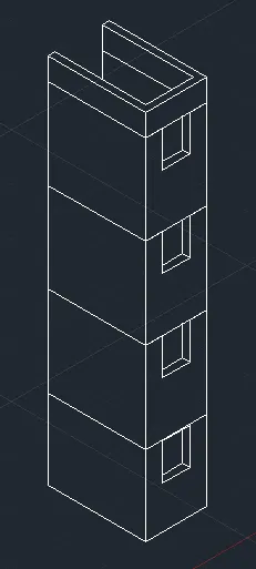
- Type 'EXT' in the command line and enter to get extrude tool
- Select the polyline and extrude 2'5" in the z direction
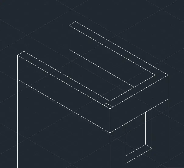
- Type 'REC' in the command line and enter to get rectangle
- Draw a rectangle of size 4"x9" on the top corner
- Type 'L' in the command line and enter to get line
- Draw a line 6'5" from center of the new rectangle in the z direction
- Draw line 6'5" from previous point in the x direction
- Draw line 6'5" from previous point in the -z direction
- Select all the lines and type 'J'
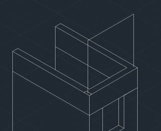
- Type 'SWEEP' in the command line and enter to get sweep tool
- Select the rectangle as the object
- Select the lines as the path
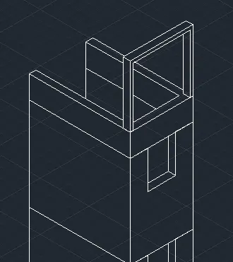
5. Create window
- Make the visual style to 'CONCEPTUAL'
- Type 'REC' in the command line and enter to get rectangle
- Draw a rectangle of 3'x4'
- Type 'EXT' in the command line and enter to get extrude tool
- Select the new rectangle and extrude 4.5" in the z direction
- Type 'REC' in the command line and enter to get rectangle
- Draw a rectangle of 2'6"x3'8" inside center of the first rectangle
- Type 'EXT' in the command line and enter to get extrude tool
- Select the new rectangle and extrude 4.5" in the z direction
- Type 'SU' in the command line and enter to get subtract tool
- Select the first rectangle and enter
- Select the second rectangle and enter
- Type 'PR' in the command line and enter to get properties
- Select the window frame and change the color
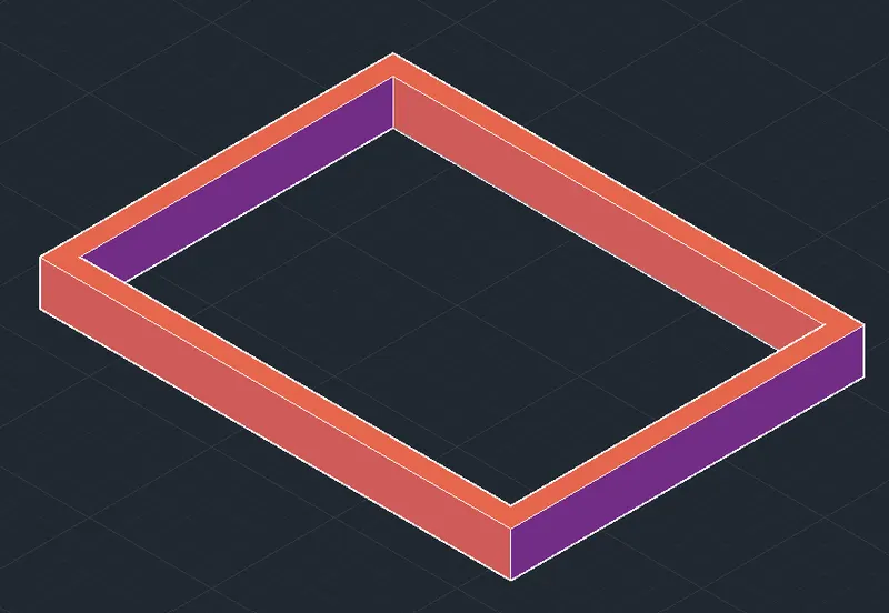
- Type 'REC' in the command line and enter to get rectangle
- Draw a rectangle of 1'4"x3'8" inside the window frame
- Type 'EXT' in the command line and enter to get extrude tool
- Select the new rectangle and extrude 3" in the z direction
- Type 'REC' in the command line and enter to get rectangle
- Draw a rectangle of 10"x3'2" inside center of the first rectangle
- Type 'EXT' in the command line and enter to get extrude tool
- Select the new rectangle and extrude 4.5" in the z direction
- Type 'SU' in the command line and enter to get subtract tool
- Select the first rectangle and enter
- Select the second rectangle and enter
- Type 'PR' in the command line and enter to get properties
- Select the inside window frame and change the color
- Type 'CO' in the command line and enter to get copy tool
- Select the 2nd window frame and paste it near it
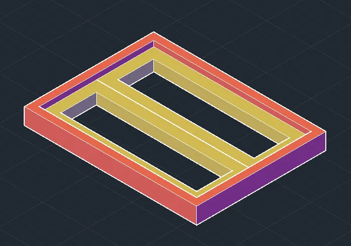
- Type 'REC' in the command line and enter to get rectangle
- Draw a rectangle of 1'14"x3'8" inside center of the second window frame
- Type 'EXT' in the command line and enter to get extrude tool
- Select the new rectangle and extrude 1" in the z direction
- Type 'M' in the command line and enter to get move tool
- Select the glass panel and paste it in the middle of the second frame
- Type 'PR' in the command line and enter to get properties
- Select the glass panel and change the color
- Type 'CO' in the command line and enter to get copy tool
- Select the glass panel and paste it near it
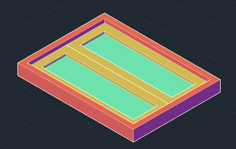
6. Place the window in the window space
- Type '3DROTATE' in the command line and enter to get 3d rotate tool
- Select the windows and rotate it according to the design
- Type 'M' in the command line and enter to get move tool
- Select the windows and place it in the window space
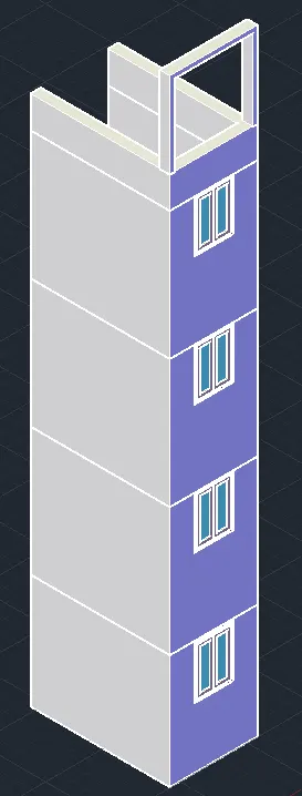
7. Create floor slabs
- Type 'EXT' in the command line and enter to get extrude tool
- Select the rectangle at the bottom level drawn at plan and extrude 6" in the z direction
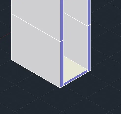
- Type 'CO' in the command line and enter to get copy tool
- Select the floor and paste it 10' above in the z direction
- Type 'PRESSPULL' in the command line and enter to get presspull tool
- Select the floor at the 1st floor and presspull 2" in the -z direction
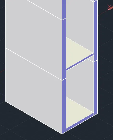
- Type 'CO' in the command line and enter to get copy tool
- Select the new floor and paste it 10' above in the z direction
- Repeat the avove step for
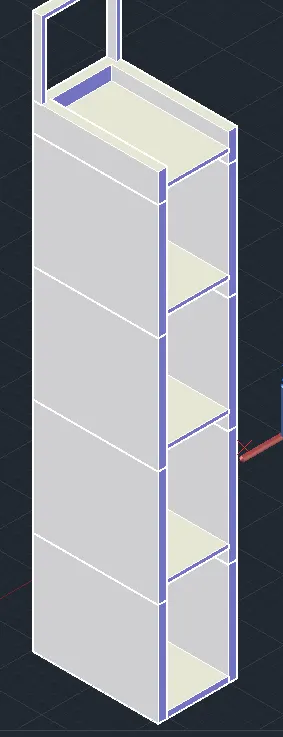
8. Change color and union objects
- Type 'PR' in the command line and enter to get properties
- Select the wall, floor and change the color
- Type 'UNI' in the command line and enter to union tool
- Select all the floors and enter
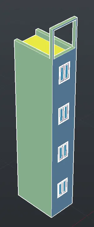
RESULT
The 3D View of the Building Façade is created as given in the plan and elevation. The different 3D view of the building is shown below
a) S-W view
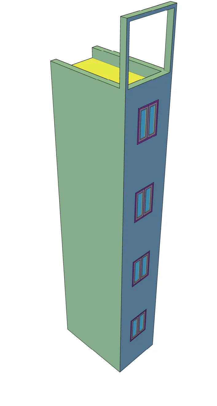
b) N-W view
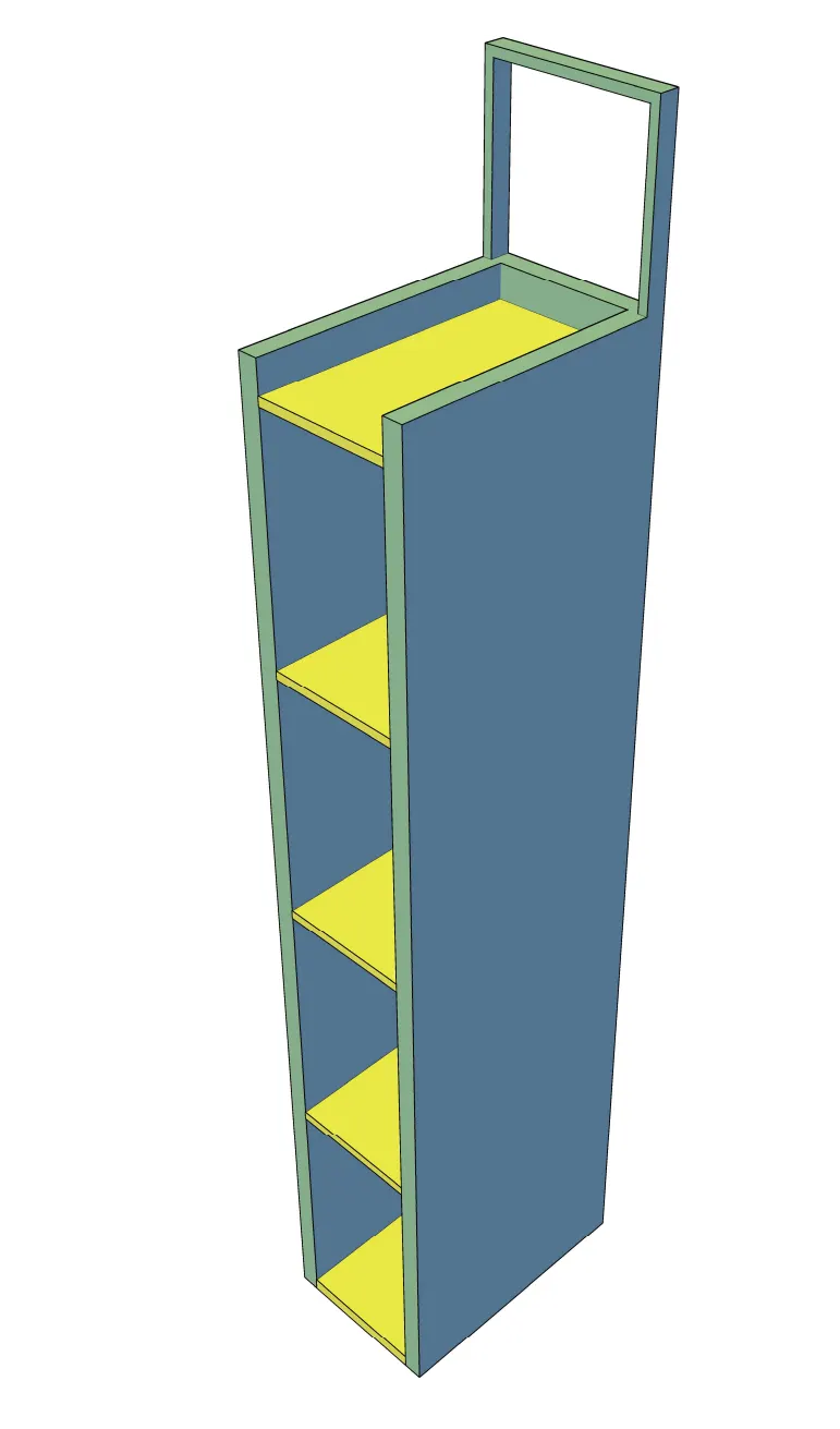
c) N-W view
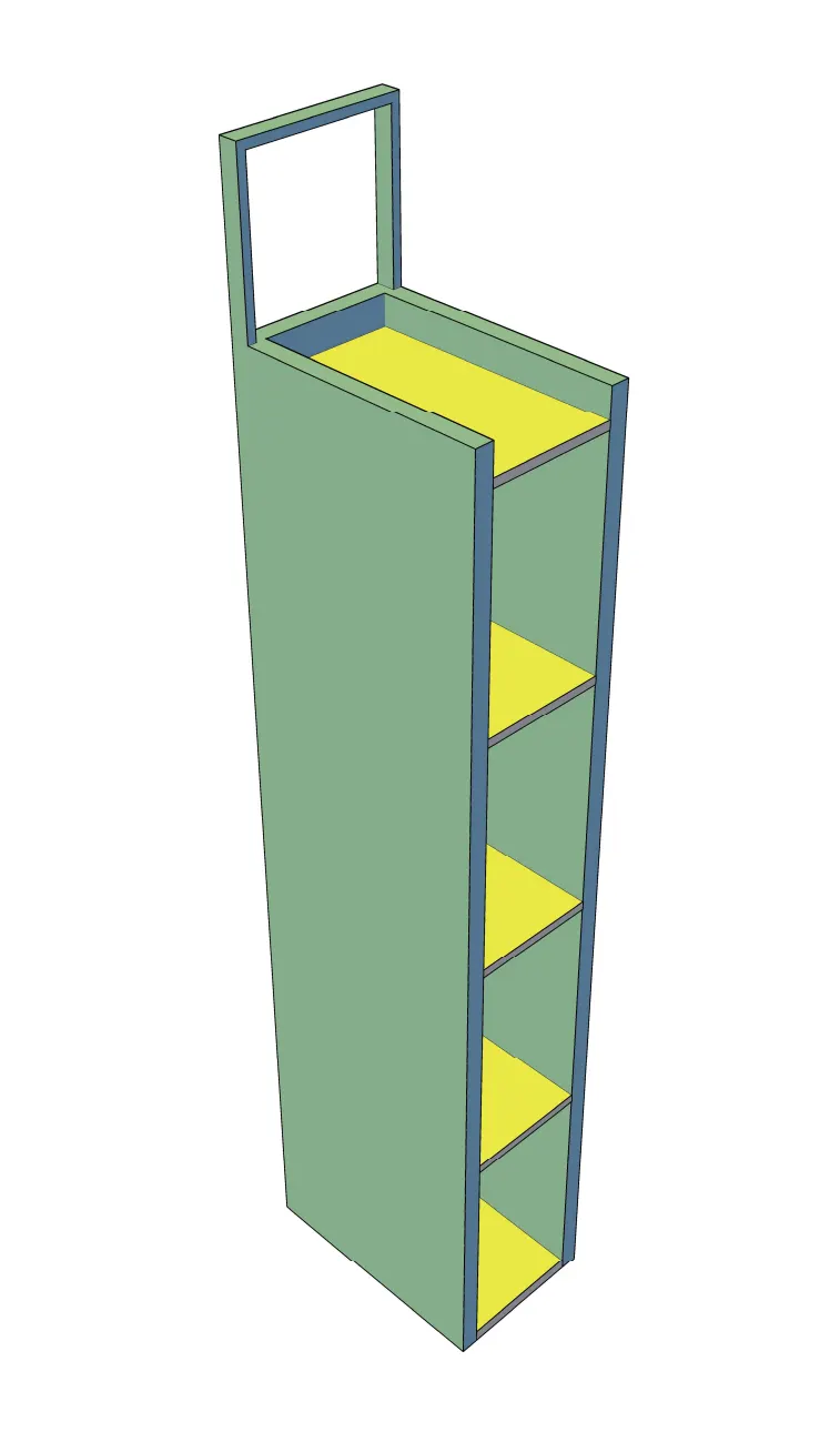
d) S-E view
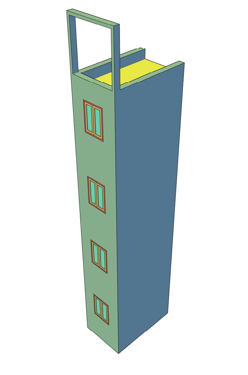
3. Create the ismoteric 3d view of a stair with railing as shown in the plan and elevation. Assume the size of the balustrades and the hand rails.
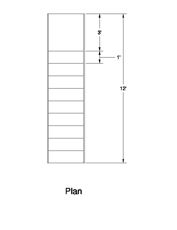
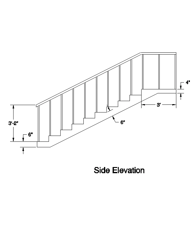
AIM
To create the ismoteric 3D view of a stair with railing as shown in the plan and elevation.
INTRODUCTION
3D modeling in AutoCAD includes 3D solids, surfaces, meshes, and wireframe objects. Several types of 3D modeling are available in AutoCAD.
PROCEDURE
Open the AutoCAD Application and create a new AutoCAD file with imperial settings. Set the length type in 'Engineering' and precision (0'-0"), insertion scale to 'Inches' in the Drawing Units and press OK. Set limits and zoom all.
Click on 'Workspace Switching' and select '3D Modelling'
1. Draw the stairs in yz plane
- Type 'L' in the command line and enter to get line
- Draw line 6" in the z direction and 1' in the y direction
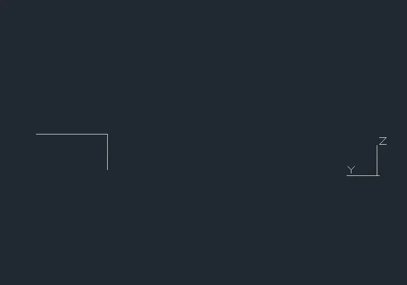
- Type 'CO' in the command line and enter to get copy tool
- Select the lines and paste above it for 8 times
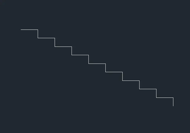
- Type 'L' in the command line and enter to get line
- Draw line 6" from the top point in the z direction and 3' in the y direction
- Draw line 4" from the previous point in the -z direction and extend line in the y direction
- Draw a extended line from bottom point in the y direction
- Draw a line from bottom corner of 9th step to bottom corner of 1st step
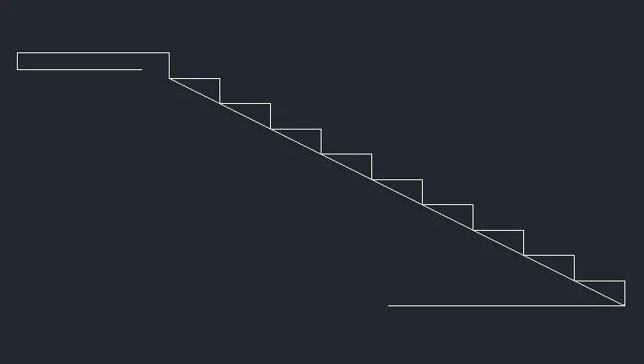
- Type '3DMOVE' in the command line and enter to get 3D move tool
- Select the step line and move 6" in the -z direction
- Join all extended lines towards the stair line
- Select all lines and type 'J' to join all lines
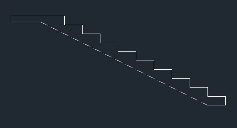
2. Extrude the step in isometric view
- Type 'EXT' in the command line and enter to get extrude tool
- Select the lines and extrude 3' in the x direction
- Make the visual style to 'CONCEPTUAL'
- Type 'PR' in the command line and enter to get properties
- Select the stair and change the color
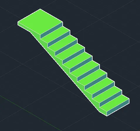
3. Draw the balustrades
- Type 'CYL' in the command line and enter to get cylinder
- Draw a cylinder of 1" diameter, 3'2" height and place it in the 1st step
- Type 'PR' in the command line and enter to get properties
- Select the balustrade and change the color
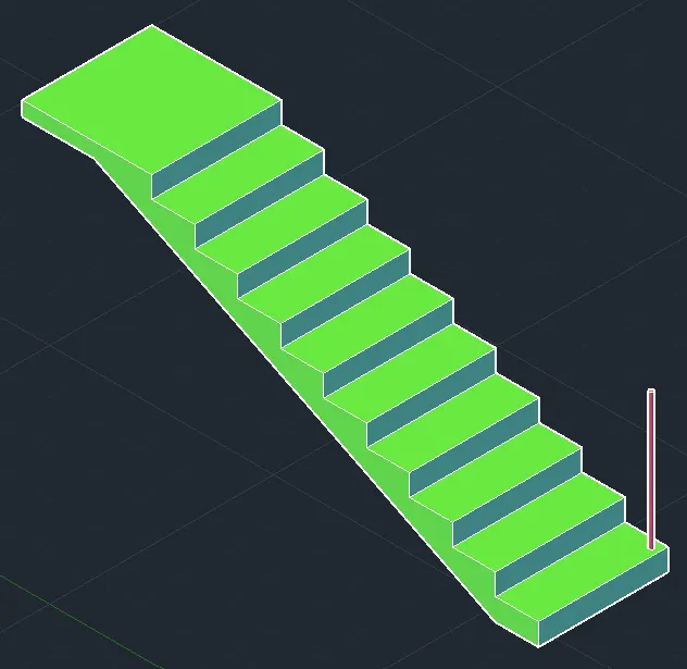
- Type 'CO' in the command line and enter to get copy tool
- Select the balustrade and paste above it according to the design
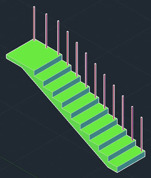
4. Draw the hand rails
- Type 'L' in the command line and enter to get line
- Draw a line from top of the first balustrade connecting the last balustrade
- Select all lines and type 'J' to join all lines
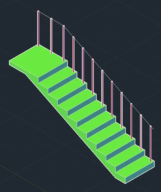
- Type 'C' in the command line and enter to get circle
- Draw a circle of radius 1"
- Type 'SWEEP' in the command line and enter to get sweep tool
- Select the circle as the object
- Select the line as the path
- Type 'PR' in the command line and enter to get properties
- Select the hand rail and change the color
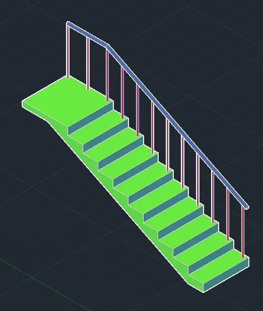
5. Place the balustrades and handrails on the other side
- Type 'CO' in the command line and enter to get copy tool
- Select the balustrades, handrails and paste it on the other side according to the design
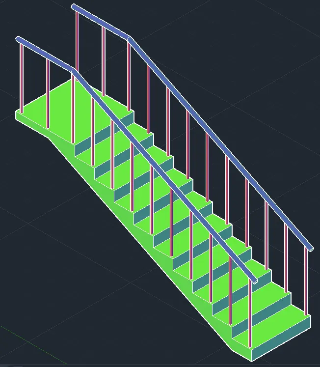
RESULT
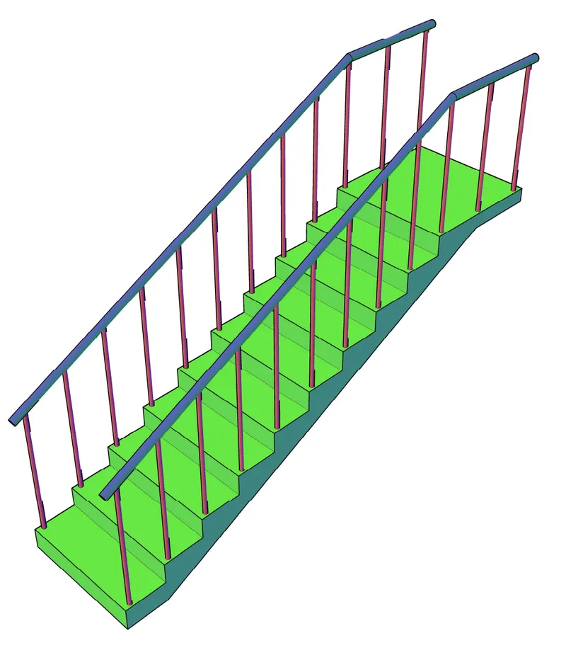
The ismoteric 3D view of a stair with railing is created as shown in the plan and elevation. The different 3D view of the stair is shown below
a) S-W view
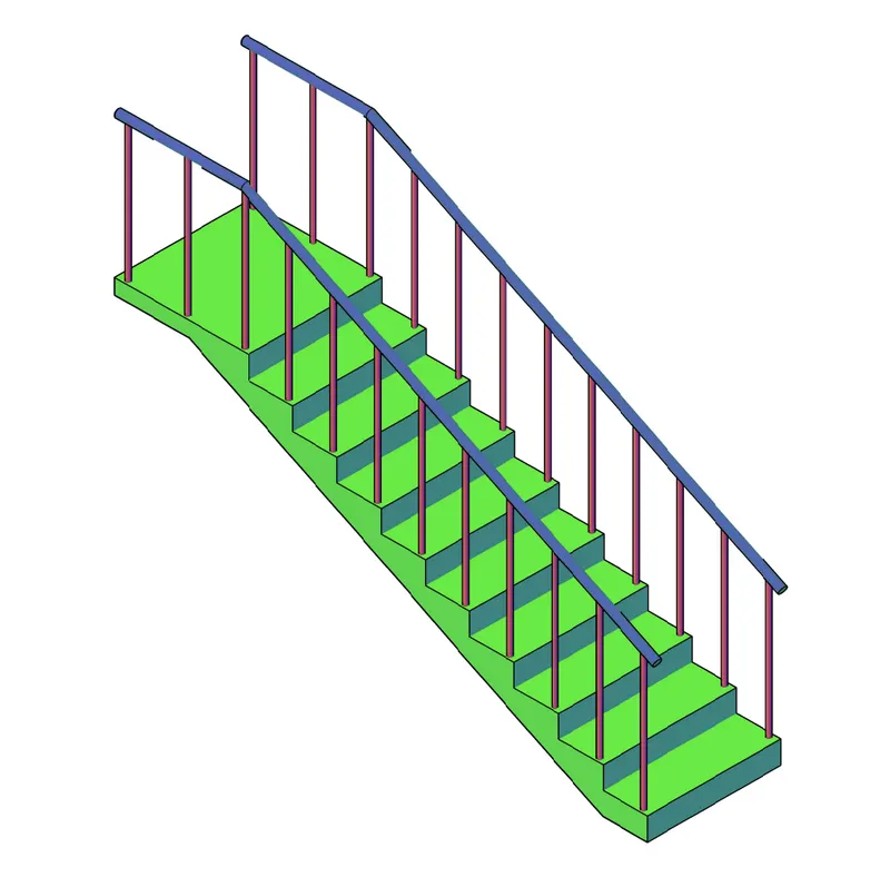
b) N-W view
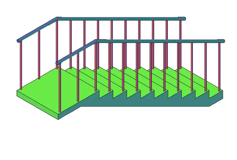
c) N-W view
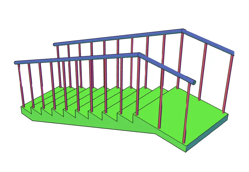
d) S-E view
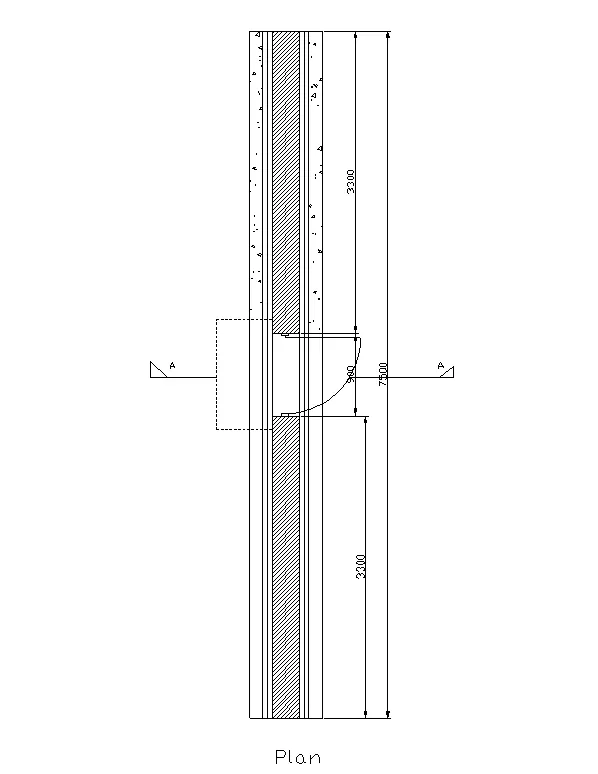
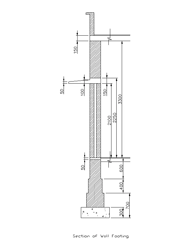
4. Create the 3D view of a Wall with spread footing . Create the Door opening only. Assume the size of the parpaet and the coping. See the plans and elevation for the details. Also, create a rendered view of the model with materials as of your choice.
AIM
To create the 3D view of a Wall with spread footing with rendered view of the model.
INTRODUCTION
3D modeling in AutoCAD includes 3D solids, surfaces, meshes, and wireframe objects. Several types of 3D modeling are available in AutoCAD.
PROCEDURE
Open the AutoCAD Application and create a new AutoCAD file with imperial settings. Set the length type in 'Decimal' and precision (0), insertion scale to 'Milllimeters' in the Drawing Units and press OK. Set limits and zoom all.
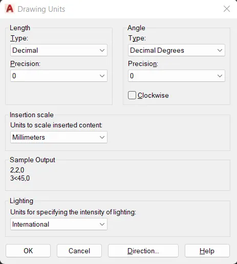
Click on 'Workspace Switching' and select '3D Modelling'
1. Draw the wall with spread footing in the plan view
- Type 'REC' in the command line and enter to get rectangle
- Draw a rectangle of size 800mmx7200mm
- Draw a rectangle of size 500mmx7200mm inside the middle of the first rectangle
- Draw a rectangle of size 400mmx7200mm inside the middle of the first rectangle
- Draw a rectangle of size 300mmx7200mm inside the middle of the first rectangle
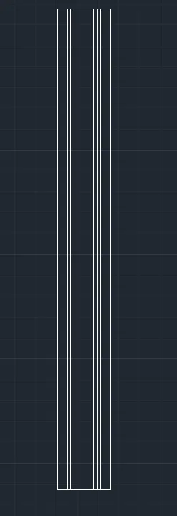
2. Extrude the spread footings
- Type 'EXT' in the command line and enter to get extrude tool
- Select the first rectangle and extrude 300mm in the z direction
- Type '3DMOVE' in the command line and enter to get 3D move tool
- Select the other rectangles and move 300mm in the z direction
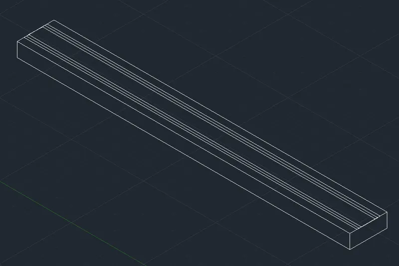
- Type 'EXT' in the command line and enter to get extrude tool
- Select the second rectangle and extrude 400mm in the z direction
- Type '3DMOVE' in the command line and enter to get 3D move tool
- Select the other rectangles and move 400mm in the z direction
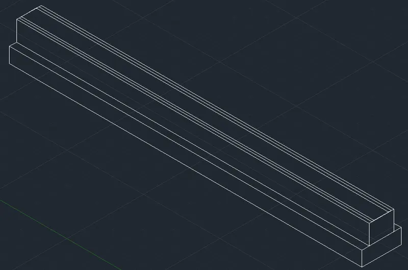
- Type 'EXT' in the command line and enter to get extrude tool
- Select the third rectangle and extrude 400mm in the z direction
- Type '3DMOVE' in the command line and enter to get 3D move tool
- Select the fourth rectangle and move 400mm in the z direction
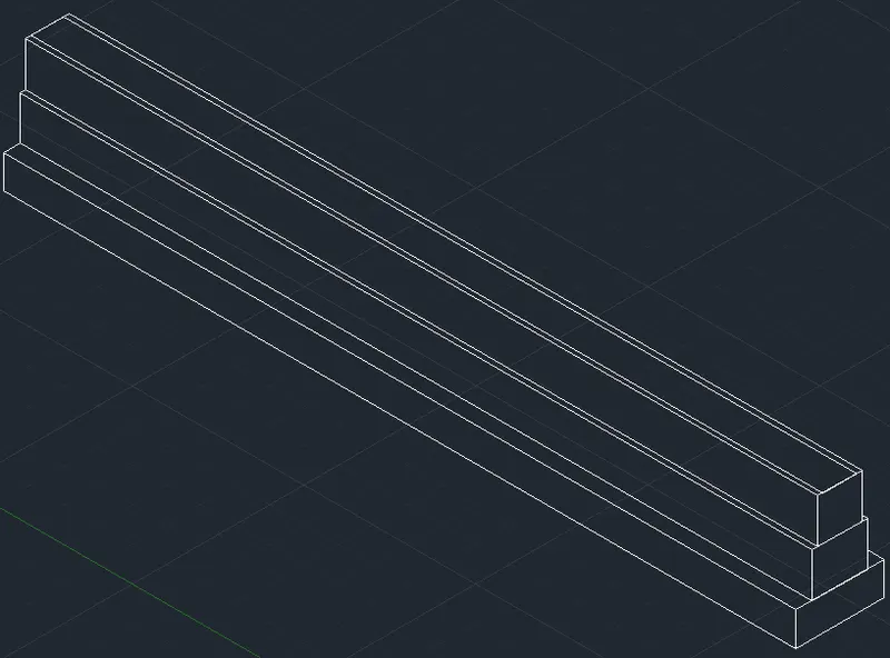
- Type 'EXT' in the command line and enter to get extrude tool
- Select the fourth rectangle and extrude 600mm in the z direction
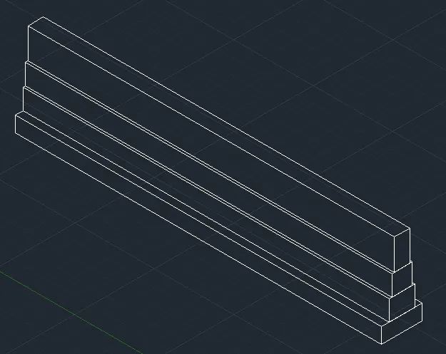
3. Create wall and door at the footing level in the plan view
- Type 'REC' in the command line and enter to get rectangle
- Draw a rectangle of size 300mmx7500mm for wall
- Draw a rectangle of size 300mmx900mm for door
- Type '3DMOVE' in the command line and enter to get 3D move tool
- Select the wall rectangle and place it above the footing
- Select the door rectangle and place it above the middle of the footing
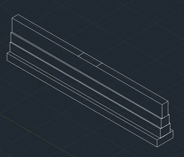
4. Extrude the wall and door
- Type 'EXT' in the command line and enter to get extrude tool
- Select the wall and extrude 3300mm in the z direction
- Select the door and extrude 2100mm in the z direction
- Type 'SU' in the command line and enter to get subtract tool
- Select the wall and enter
- Select the door and enter
- Make the visual style to 'CONCEPTUAL'
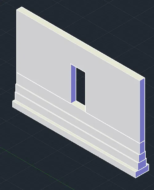
5. Create sunshades
- Type 'REC' in the command line and enter to get rectangle
- Draw a rectangle of size 100mmx1200mm
- Draw a rectangle of size 50mmx1200mm
- Type '3DMOVE' in the command line and enter to get 3D move tool
- Select the rectangles and place it above the middle of the door
- Select the 50mmx1200mm rectangle and place it 600mm in the -x dirextion
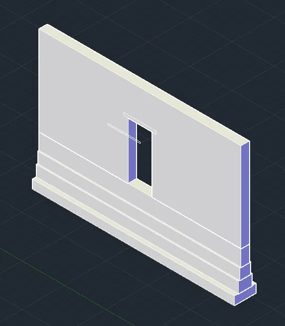
- Type 'LOFT' in the command line and enter to get loft tool
- Select the two rectangles and enter
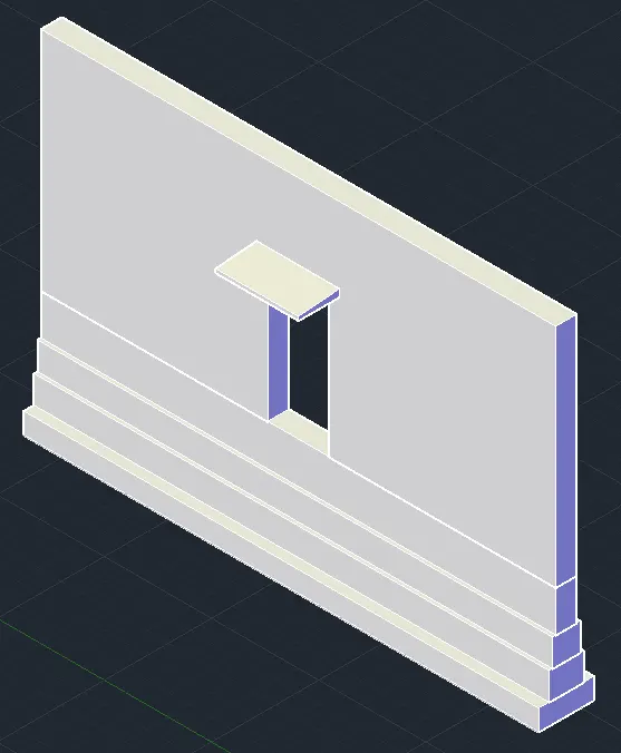
6. Create the floors
- Type 'REC' in the command line and enter to get rectangle
- Draw a rectangle of size 1600mmx7500mm in the xy plane on the top of the wall
- Draw a rectangle of size 7500mmx100mm in the yz plane below the door opening
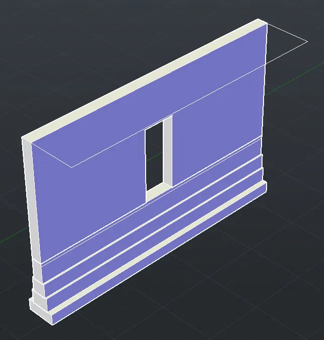
- Type 'EXT' in the command line and enter to get extrude tool
- Select the rectangle 1600mmx7500mm and extrude 150mm in the z direction
- Select the rectangle 7500mmx100mm and extrude 1600mm in the x direction
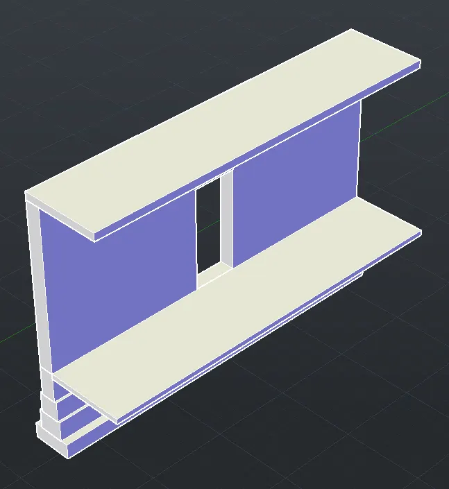
7. Create parapet wall
- Type 'REC' in the command line and enter to get rectangle
- Draw a rectangle of size 100mmx7500mm in the xy plane on the top of the floor
- Type 'EXT' in the command line and enter to get extrude tool
- Select the rectangle and extrude 900mm in the z direction
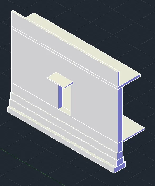
- Type 'REC' in the command line and enter to get rectangle
- Draw a rectangle of size 50mmx7500mm in the yz plane on the top of parapet wall
- Type 'EXT' in the command line and enter to get extrude tool
- Select the rectangle and extrude 100mm in the -x direction
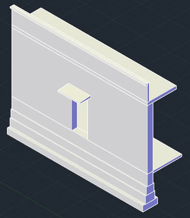
8. Change the materials of the objects
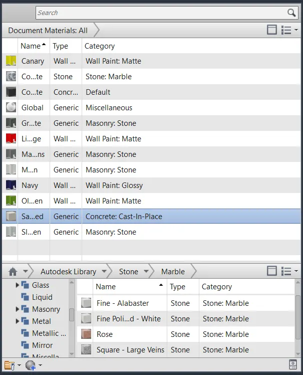
- In 'Visualize' tab, click on the 'Material Browser'
- Assign different materials to different objects
- Make the visual style to 'REALISTIC'
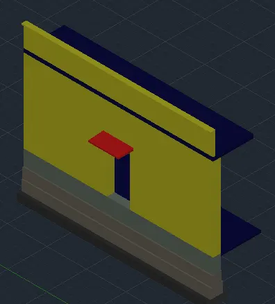
9. Create rendered view
- Type 'RR' in the command line and enter to get rendering option
- Below shown rendering is done using region
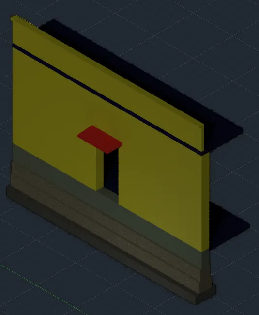
RESULT
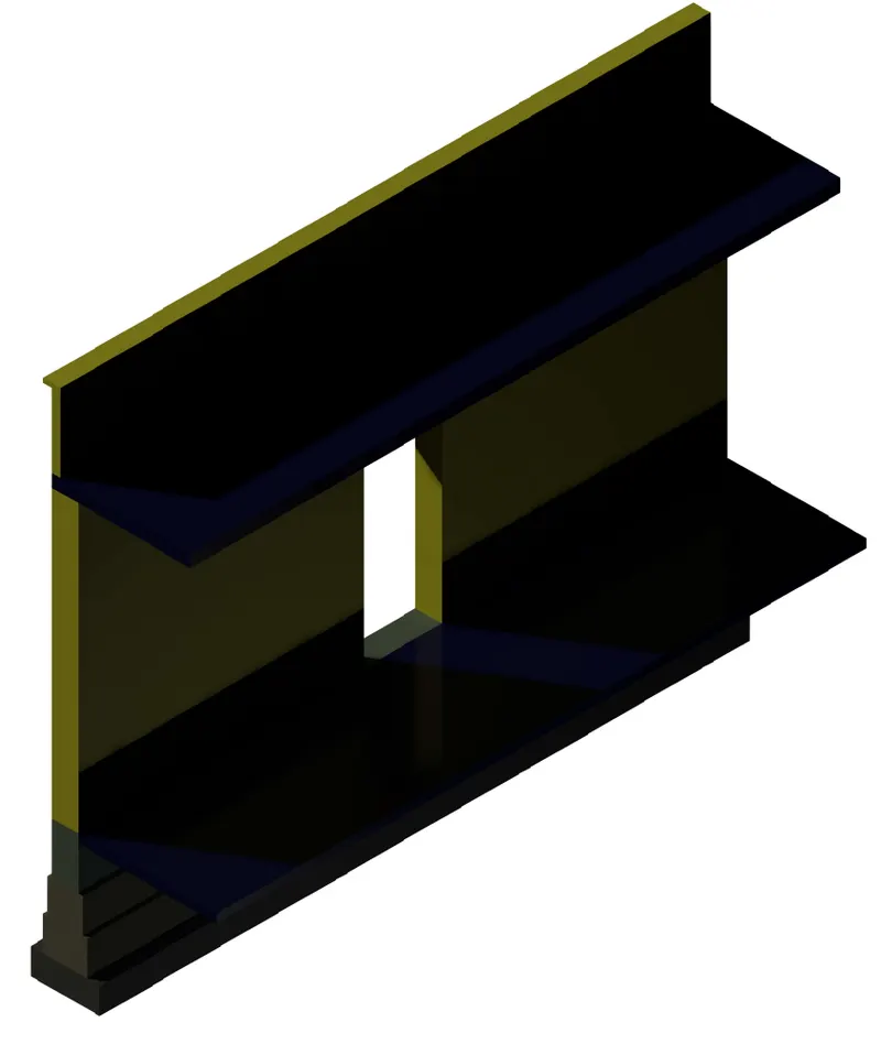
The 3D view of a Wall with spread footing is created with rendered view of the model. The different rendered 3D view of the model is shown below
a) S-W View
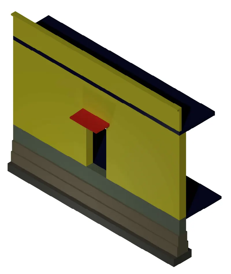
b) N-W view
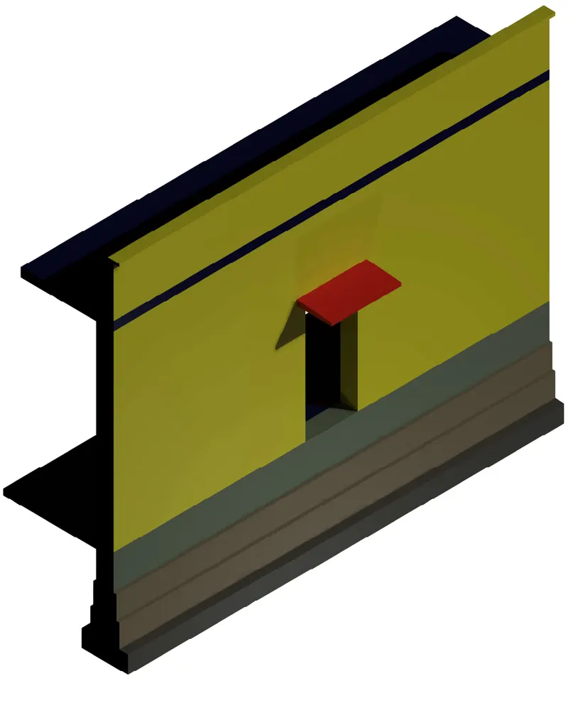
c) N-E View
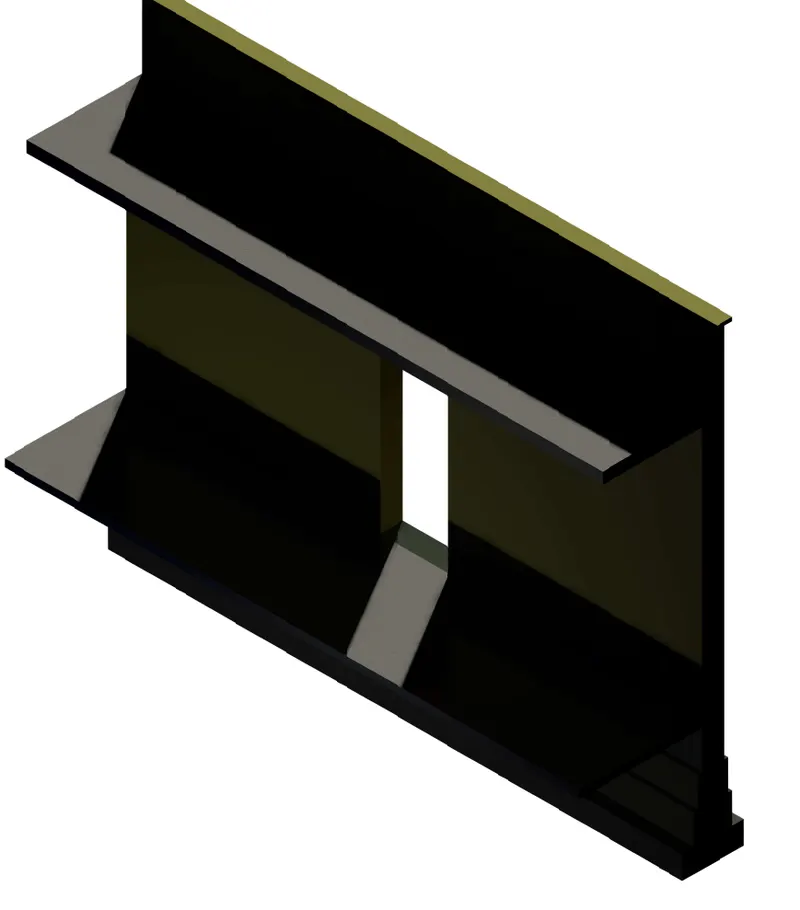
d) S-E view