Creating 3D Isometric view of various structural elements in AutoCAD
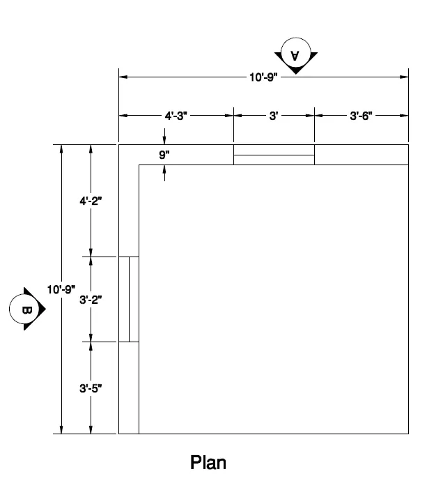
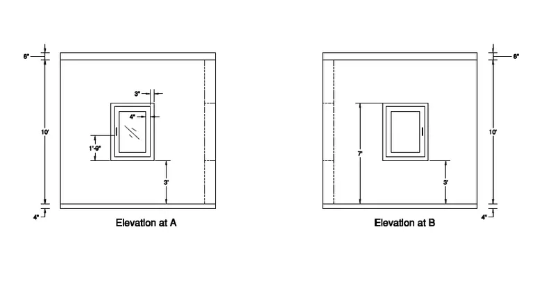
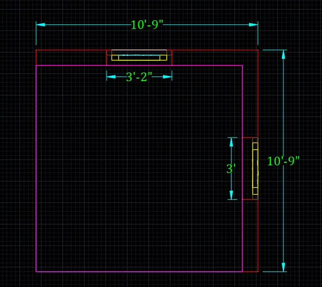
1) AIM: Create a 3D Isometric View of the building with plan and elevation given
Procedure:
Steps:
- Open Autocad in imperial system
- Use line command to create plan with 9" wall thickness
- Use rec commad to create plan for windows
- Use boundry command to give the surface to walls
- Extrude the walls at a height of 10'10"
- Now select 2d wireframe
- Use extrde commad to extrude wall at a height of 4'
- Use move command to move the windows 3'4" height
- Use boundry Command to give surface to floor and extrude it 4"
- Now use rec and offset command to create windows (3'x4' & 3'2"x4') with frames
- Now Provide Colour using properties
Result:
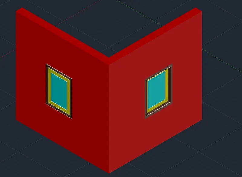
SW Isometric View:
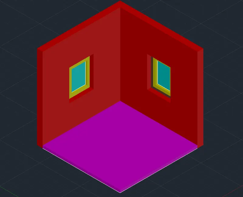
NE Isometric view:
Plan in 2D wireframe
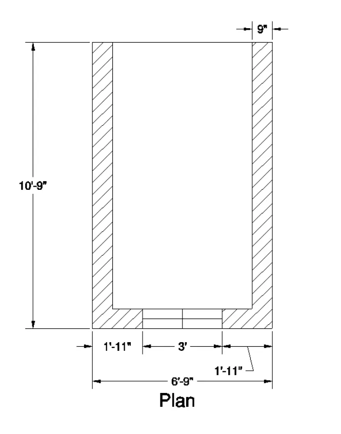
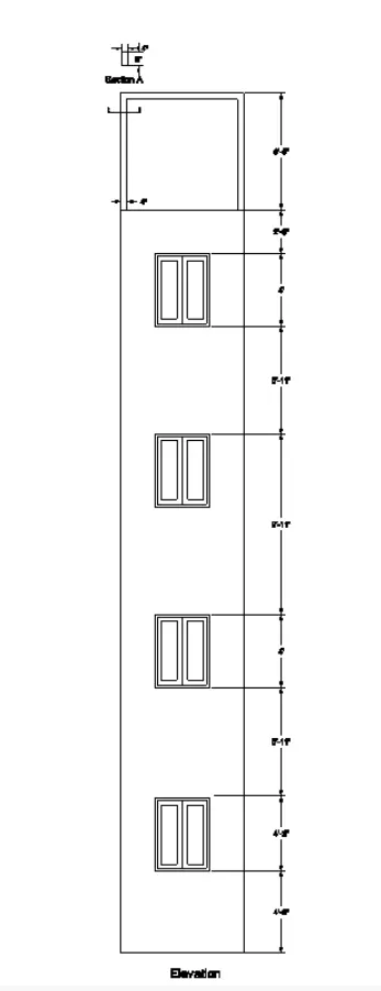
2) AIM: Create the 3D View of the Building Façade as given in the plan and elevation. Also, see the detail of the window.
Procedure:
Steps:
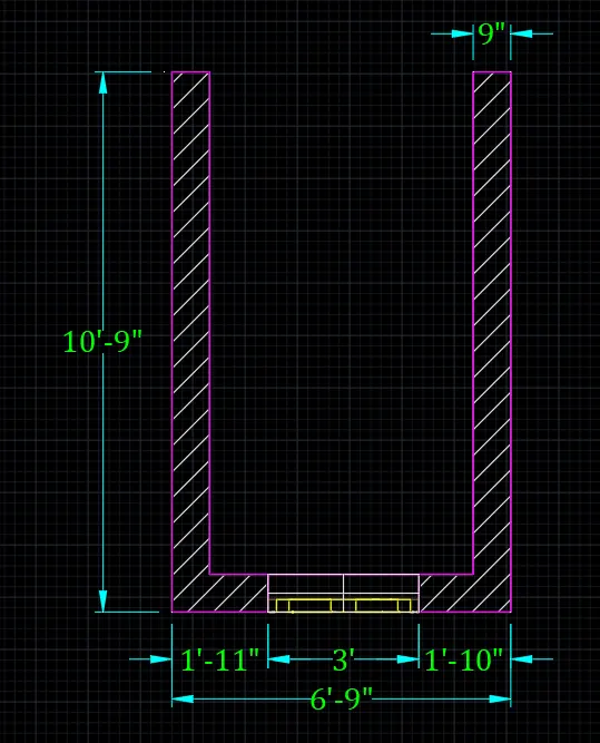
- Use Line command to create the plan
- Use rec command to create windoe panel
- Use hatch command to povide hatch
- No Use boundary command to prvide surface
- Extude the Surface at a height of 9'11"
- Now select 2d wireframe
- Now extrude the window at a height of 4'
- Move the window at a height of 4'6" upwards
- Use Subtract command to delete the window frame from wall
- Use rec and line command to create window panel
- Use properties to assign colours
- Use copy command to copy it 3 times for 4 floors
- Use dimlinear command to provide dimensions
Result:
Plan:
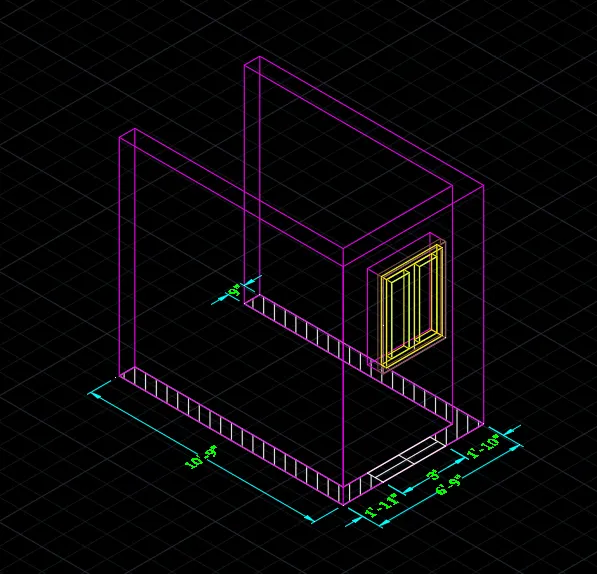
SW Isometric view
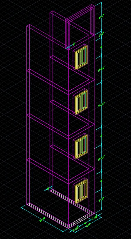
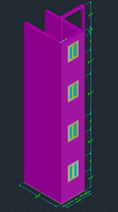
Complete View
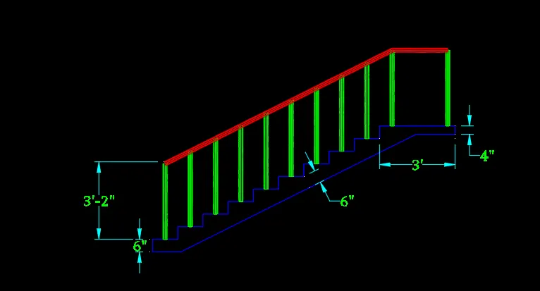
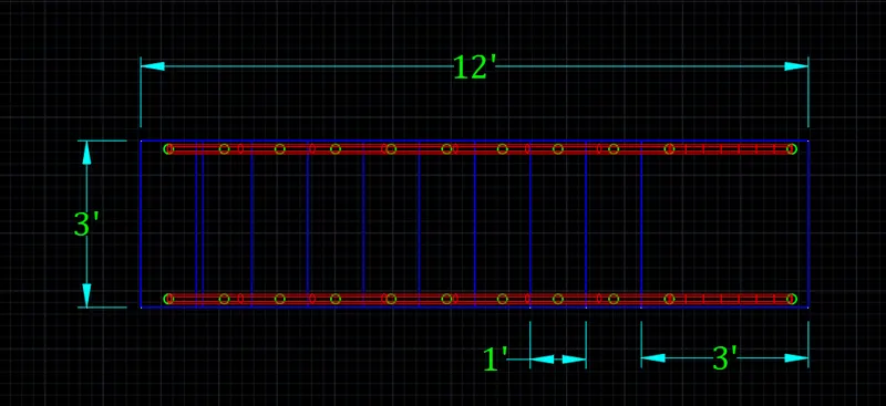
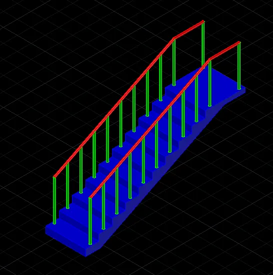
3) AIM: Create the ismoteric 3d view of a stair with railing as shown in the plan and elevation. Assume the size of the balustrades and the hand rails
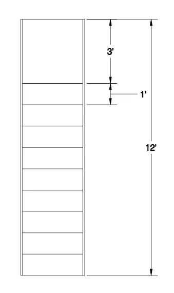
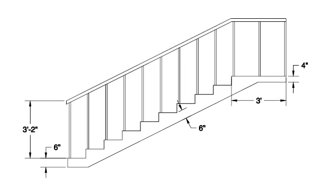
Procedure:
Steps:
- Use Ucs option And switch y and z axis
- Use line command And make one step of stair
- Use copy command and copy the step 9 more times
- Take Slab width of 6" for stairs
- Now use boundry command to give surface of the stair
- Extrude the stair in y axis - 3'
- Now use circle command to make a circle of 1" radius on the first tep of stair
- Extrude the circle at a height of 3'
- Copy the cylinder in every step of stair
- Use polyline commad and make a line passing through the cylinders
- make a circle of 1" and sweep the circle along the polyline
- Use 3dmirror to mirror the stair railings to other side of stair
- Now use properties option to give solids different colors
- Use dimlinear command to provide dimensions
Result:
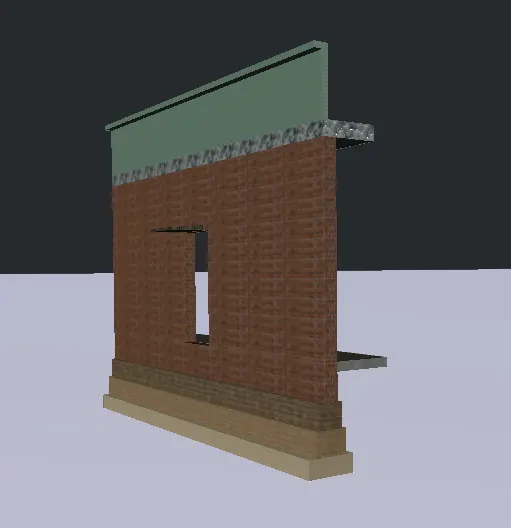
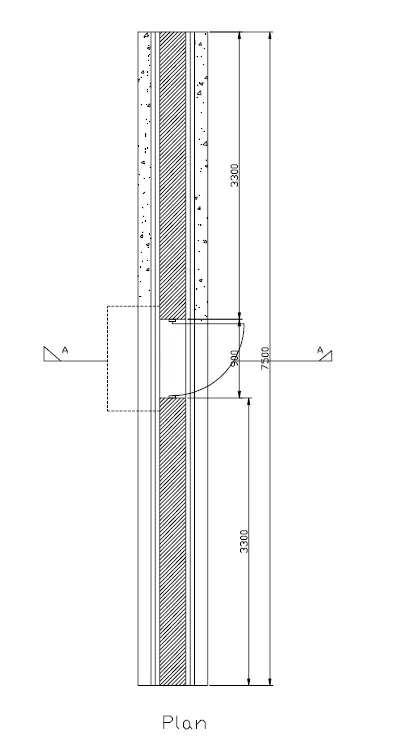
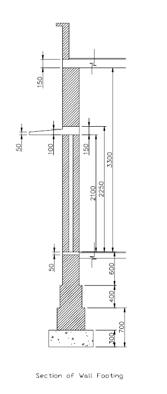
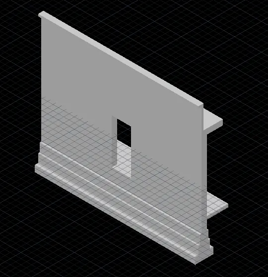
4) AIM: Create the 3D view of a Wall with spread footing
Procedure:
Steps:
- Open A new Autocad drawing
- Use line command to create the section of the wall with spread footing
- Use hatch command to provide hatch to the section
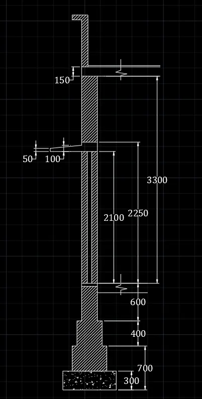
- Now Use rec command to create the side section again
- Use region command to create the surface
- Now use the extrude command to extrude the section of wall in y axis
- length of wall is 7500
- Now create the rectangel of 250x900 in the ground level
- Give the surface and extrude the rec at a height of 2100
- Use subtarct command and subtract the door frame
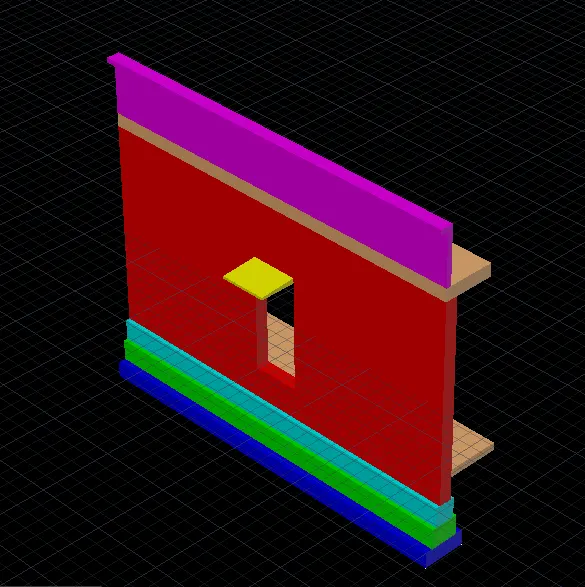
- Now Use Propertie option to give different colours
- Now goto visualize tab
- Select material browser and assign material for different solids
- Use render view option to see the view
- Also uselect camera and place a camera for a better view
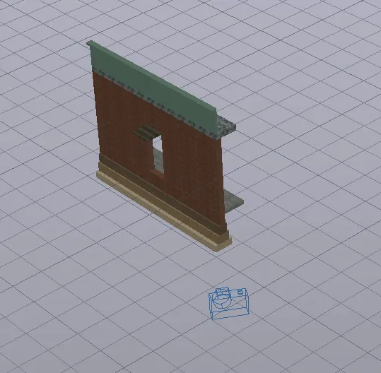
Result:
Render View
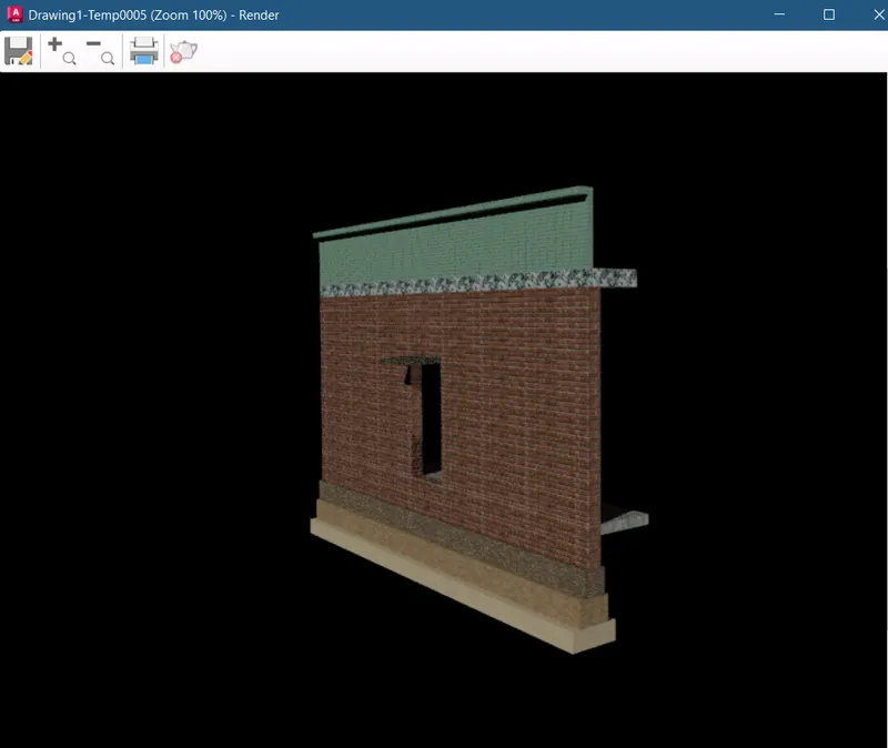
Camera View