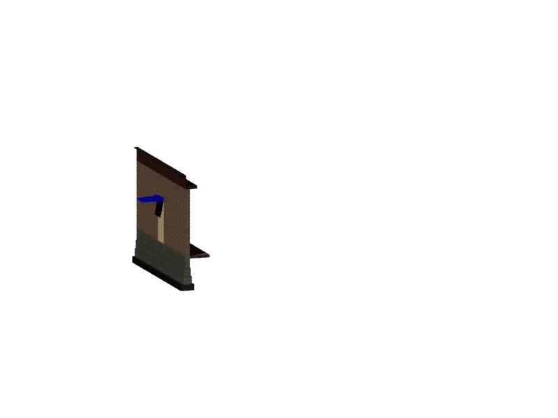
Creating 3D Isometric view of various structural elements in AutoCAD
Challenge:1
Aim: To draw the 3D Isometric view of the building with the given elevation and plan details.
Introduction: A plan view of both the walls of the building, elevation details from both sides along with the necessary dimensions are provided which is to be converted into a 3D model.
2 window openings with its frame dimensions, handle height and width are also provided.
Height of the window from the floor level is 3’, whereas the thickness of the bottom floor is 4” & that of the roof is 6”. Height of the building is 10’.
Procedure in Detail: Obviously first open AutoCAD, then setup units which is to setup the dimension or measurement format of the particular AutoCAD file with the help of which the dimensions would be measured and represented as given.
Change the workspace settings from drafting to 3D modelling.
Step:1
create layers and work accordingly.
Step:2
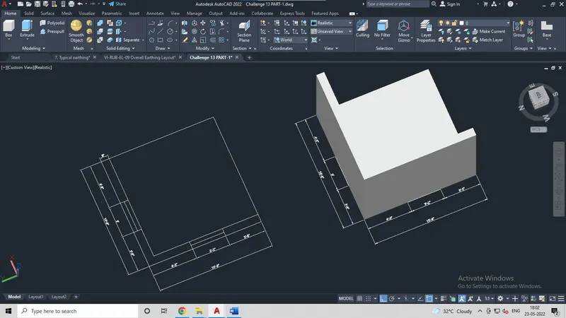
Use 3D polyline with the help of which create a square of dimension 10’ - 9” X 10’ - 9”.
Use Offset command at 9” from any point of the square towards inside of the square and then explode the inner square.
Later, from the top left-hand side and the right bottom end delete lines and extend the lines to the edges of the outer square as shown in figures.
Draw windows of the dimensions with width of 3’ & 3’-2” as provided in the challenge at the given distance from both edges and as per other details shown in the questionnaire.
Step:3
Now extrude the wall of 9” at an height of 10’.
And also extrude the bottom floor to the height at 4”.
Taking the bottom square of dimension 10’ - 9” X 10’ - 9” extrude it too, to the height of 6” which will be used to place above the building height as roof to the building.
Step:4
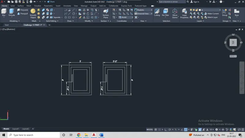
As the details are provided where the window dimensions can be known, such as the window width, height, thickness, its inner frame thickness, height at which the handle is placed.
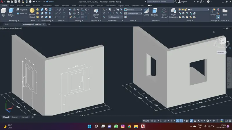
With all such details prepare a plan view of windows for both elevations as shown in below snap.
Step:5
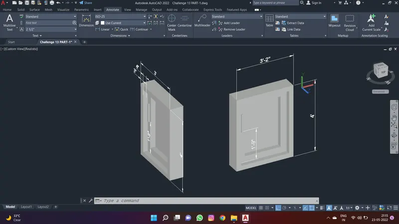
Now go for 3D rotate and rotate both the elevations of windows at 90 degree from base level.
With the help of commands such as extrude, presspull and subtract create the 3D required image of the window, which is also represented in the snap below.
Step:6
The 2D plan view of the window should be placed at a height of 3’ from the floor level as asked.
The same should be done for both windows of both the sides of the building (refer the image provided for better understanding)
Next all you need to do is use presspull command towards inside at 9”and subtract from the outer frame so that space for window frame is obtained (refer the image provided for better understanding).
Step:7
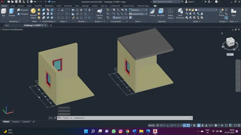
Color/ choose layer color for the windows, its glass its frame and the building wall and roof according to your choice.
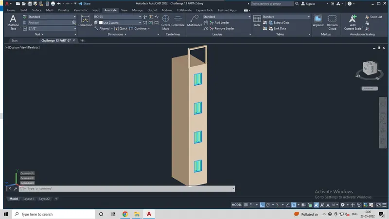
Now assemble each and every part (i.e. both the windows in the sectional space created & the roof) together to form it as a final product which is the 3D model of the building.
Result:
Thus, after assembling each and every part the final product which is the 3D model of the building is obtained.
Challenge:2
Aim: To draw the 3D view of building façade and its window with the help of given elevation, plan & window details.
Introduction: Plan view of the building base is provided along with its front elevation and window details.
Not only just the views but also dimensions of the building base, windows and the total height of the building can be known by adding up all the distances between windows, difference of height from base and roof.
NOTE: Kindly note, that there are certain dimension errors which means a few dimensions provided are wrong such as the height of the first window which is at a height of 4’-6” from ground floor is shown as 4’-2”, but every window is of the height 4’.
Secondly, talking about the window detailing, width of the inner most rectangle which can be considered as glass is shown as 11”. But considering the width of the frame as 3’, the inner most rectangle cannot be of 11” and thus it is considered as 10” as per other window dimensions & the width of the window provided which is 3’.
Procedure in Detail:
Open AutoCAD, setup units which is to setup the dimension or measurement format of the particular AutoCAD file.
Change the workspace settings from drafting to 3D modelling.
Step:1
Create layers and work accordingly.
Create layers for building, windows, window glass and any other object that is drawn.
Not only that, while creating layers do not forget to choose colors for every particular thing so that the object is formed from the very start in color format.
Step:2
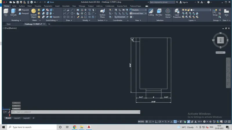
Create the 2D plan view as shown in the given details according to the given dimensions.
Take 3D polyline, set the axis to the top view which will help in drawing the plan view easily.
Draw a rectangle of the dimension 6’-10” X 10’-9” at any point on the workspace.
Offset the rectangle at 9” towards inner side of the rectangle and thus another rectangle inside the outer one will be formed.
Explode the inner rectangle and delete the topmost line and then extend the side lines to the edges of the outermost rectangle.
Draw the window of dimension 3’ width at the given distances which is 1’-11” from both the ends thus that will increase the total width of the building to 6’-10” instead of the given width which was 6’-9”.
Step:3
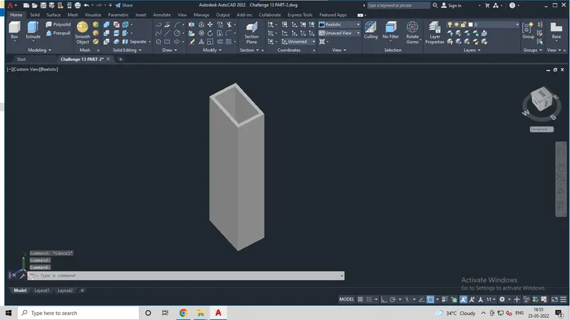
Now use Extrude command and extrude the whole plan view which is the rectangle structure formed to the height of 40’ – 2”.
Step:4
Creating Window with the elevations provided.
Draw rectangle of 3’ X 4’ for window with the help of given dimensions.
Offset the rectangle towards inside at 2”. Now draw a center line and draw a rectangle considering the two edges one of the center line and the other edges is of the inner most offset rectangle’s top left edges.
After a rectangle is drawn remove any other previous lines like the offset rectangle & the center line too.
Now use Copy command and copy the newly formed rectangle side by side which is still at an offset of 2” from the outer most rectangle from both the side ends.
Take an offset at 3” from the newly copied rectangle which is at 2’ from the outer one and thus the same should be repeated on the other side of the center line.
Thus, a Plan view of the windows will be formed which is to be rotated at 90 degree with the help of 3D rotate.
After it is rotated do select the colors for the window frame and glass also mention the dimensions.
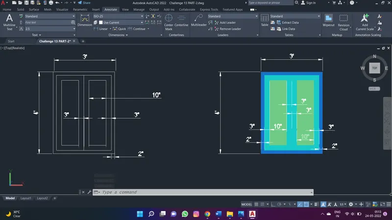
Step:5
Now place the 2D plan view of the window which is rotated at 90 degree on the extruded building at the dimensions asked. Like place the window from the ground level at 4’-6” height, similarly the height difference from the top of the first window to the bottom of the 2nd window is 5’-11” and similarly other dimensions are also followed and the 2D view is placed over the building.
Use presspull command and select the outer most rectangle of the window plan view and pull the inner part towards inside at 9” so that the window portion is only subtracted from the whole building façade structure.
Similarly do the same for all the windows and as a result of which a blank structure with window frame space in between will be obtained.
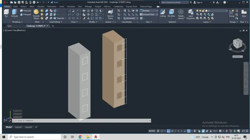
Step:6
Now working on the window portion after the 2D plan view of the window is rotated at 90degree use few commands such as extrude at extrude the outer most rectangle at 9”, so that it matches the thickness of the building.
Similarly do the same with the other rectangles too.
Use command such as presspull, extrude and subtract in some cases, in order to obtain the desired form of window and further select the color or layer of the window also add on dimensions.
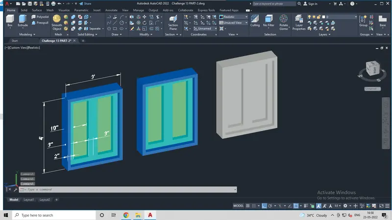
Step:7
Now create the top most part of the building, by drawing a rectangle at 6’-5” height and width will remain same as of the building which is 6’-10”.
Use Offset command and take an offset towards inside of the outer rectangle at 4”.
Now extrude the boundary of the rectangle at a thickness of 9”.
Later place the whole structure at the top of the building by matching the edges of both( i.e. the building & the top-part).
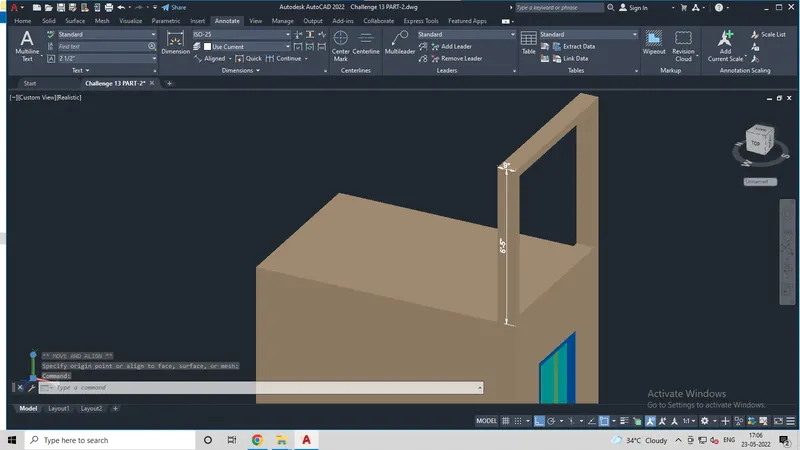
Result:
Thus, after assembling each and every part the final product which is the 3D model of the building facade is obtained with indicative dimensions.
Challenge:3
Aim: To draw the isometric 3D view of a staircase & its railing with the given elevation, plan & assuming other certain details.
Introduction: Plan view of the staircase is provided along with that the side elevation of the staircase is also provided which is to be converted or drawn in 3D.
The plan view consists of the overall dimension, the distance between two steps and the number of stairs.
The Elevation consists of side view of the staircase, vertical dimensions and also other undefined components such as hand rail, spacing from the side of the stairs and other details which are to be assumed.
The assumed dimension of hand rail & vertical rail is 1”
Procedure in Detail:
Open AutoCAD, setup units which is to setup the dimension or measurement format of the particular AutoCAD file.
Change the workspace settings from drafting to 3D modelling.
Step:1
Create layers and work accordingly.
Create layers for staircase, hand railing, vertical rails, its base and any other object that is drawn.
Not only that, while creating layers do not forget to choose colors for every particular thing so that the object is formed from the very start in color format.
Step:2
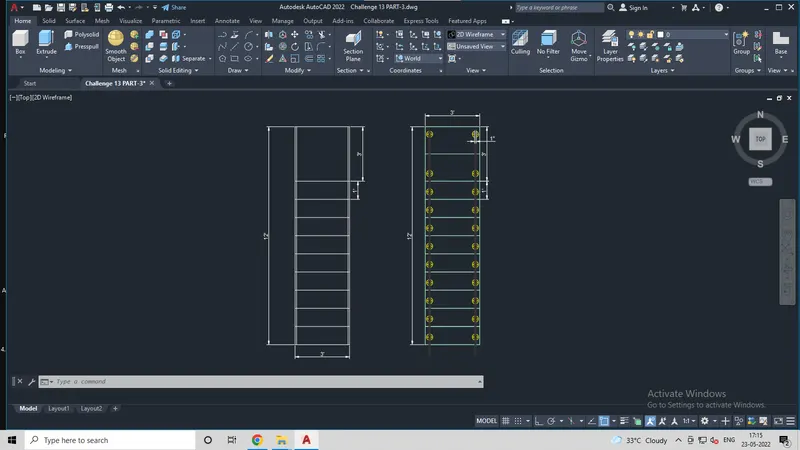
Create / Draw a 2D plan view structure of the staircase as given for that,
- Draw a rectangle of 3’ X 12’.
- Now explode the rectangle and take offset from any of the one side.
- Take offset of 1” towards inside of the vertical lines on both the sides after exploding the rectangle.
- From the bottom take offset at 1’ towards inside, repeat the same 9 times in order to make it look like steps of the staircase.
Step:3
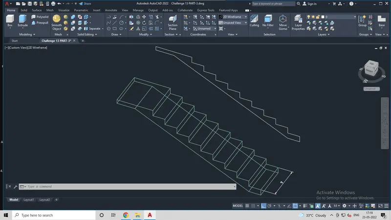
Change the view to 3D and change the view to right side view so that the further drawing can be made easily.
Set UCS as right.
Start with Line command and draw a vertical line of 6”
Draw a horizontal line of 1”.
Repeat the same process for 9 times so that the 3D view of the whole staircase is formed.
After reaching 9 steps draw a horizontal line of 3’ as shown in figure.
Now from the top edge draw a line towards downside at 4” then a horizontal line backwards at 1’-6”
From the bottom edge take a line backwards at 1’.
Then join the slab lines.
Step:4
At the end the 3D structure will be formed.
Now, Extrude the 3D staircase structure at 3’ towards any side.
Step:5
Now, to create hand rails:
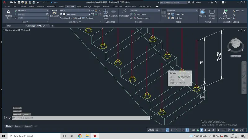
Make a circle of diameter 2” and another circle at 2” height of diameter 1”.
Use Loft command, and select both the circles to make it the base of 2” for vertical rails.
Now, make another circle of diameter 1” and extrude it to the height of 3’.
So that the total height of vertical rails becomes 3’-2” from the base of the step of staircase.
Now place this vertical rail at the base drawn for those rails by matching the center of both the things.
Now, place this whole vertical hand rail at an appropriate distance on the surface of staircase.
Copy paste the same on all the steps & on both the sides.
As shown in figure.
Step:6
Draw a polyline by connecting the top edges of all vertical hand rails.
Repeat the same for the other side of the staircase.
Draw a circle of 1” near the polyline on both the sides.
Use Sweep command and select the polyline & circle and thus solid hand rails will be created.
Copy the same for the other end too.
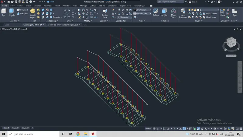
Step:7
Give dimensions from all the ends and edges and thus 3D model is created.
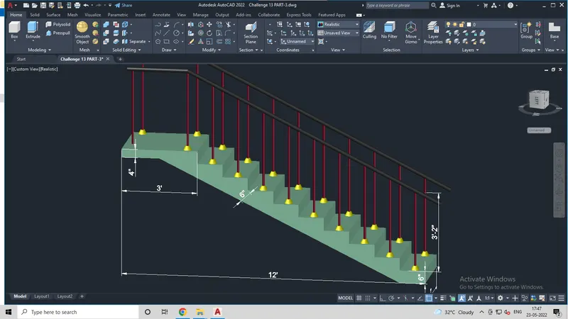
Result:
Thus, after assembling each and every part the final product which is the 3D model of the staircase is obtained with indicative dimensions.
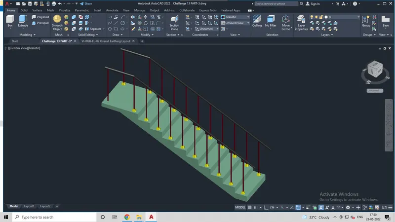
Challenge:4
Aim: To draw the 3D view of a wall with spread footing as shown in the given plan & elevation. Also, certain things are to be assumed.
Introduction: Plan view of the wall with spread footing and also elevation of the same is provided which is to be converted or drawn in 3D.
Plan view consists of Horizontal dimensions of footing and the wall.
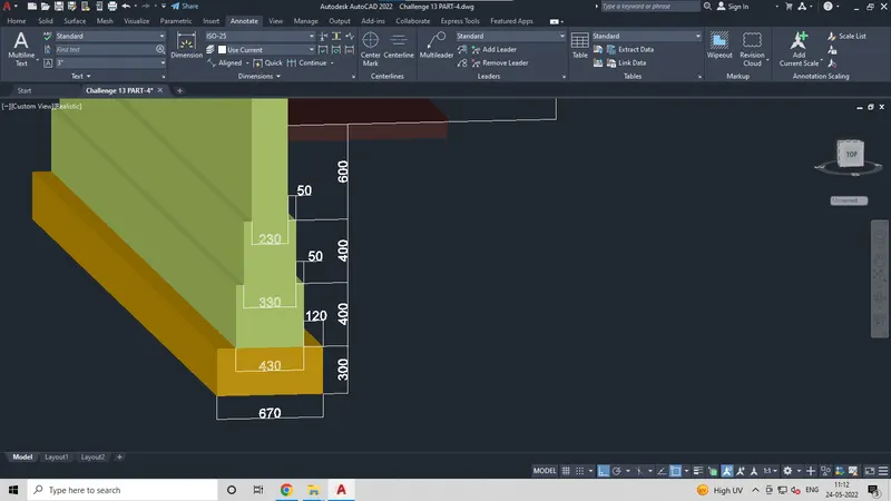
Elevation view consists of vertical dimensions on different levels. Thickness of the wall is 230mm.Some other components are to be assumed such as:
Thickness of level 1 of footing is same as of the wall i.e., 230mm
Coping thickness of level 2 is offset of 50mm than the thickness of wall
Thickness of level 3 is offset of 50mm than the thickness of level 2
And level 4 is at an offset of 120mm than the thickness of level 3.
Procedure in Detail:
Open AutoCAD, setup units into mm which is to setup the dimension or measurement format of the particular AutoCAD file.
Change the workspace settings from drafting to 3D modelling.
Step:1
Create layers and work accordingly.
Create layers for objects that are drawn.
Not only that, while creating layers do not forget to choose colors for every particular thing so that the object is formed from the very start in color format.
Step:2
Draw a rectangle of dimension 670X7500.
Take offset of the same inside at 120mm.
Take another offset of the inner rectangle at 50mm, repeat the same again.
Explode all the rectangles
Delete the top & bottom edges of the exploded rectangles.
Extend all the open lines to the edges of the outer most rectangle.
Select individual lines and change its layer.
Give dimensions to the same.
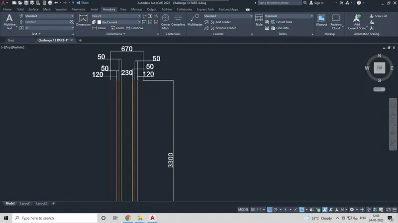
Step:3
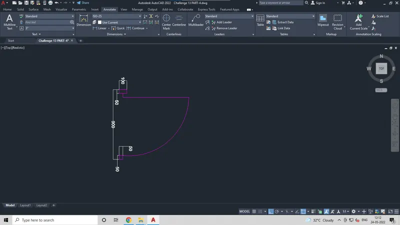
Draw a rectangle of 50X100 and another of 50X50.
Now place the small square 50X50 at a distance of 900 from the bigger block 50X100.
Draw a line of 850mm and form an arc connecting it to the other end.
Convert the whole drawing into a block.
Step:4
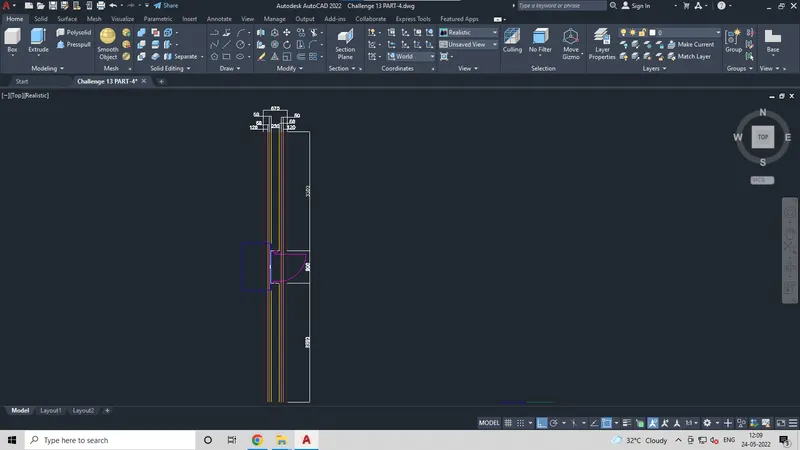
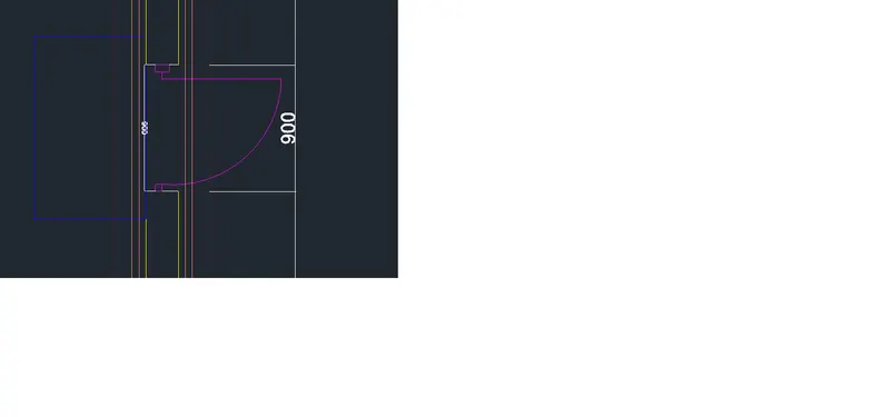
Place the door opening of 900mm in the center.
Add the door block to the wall structure.
Step:5
Draw a line of certain length, take an offset at 25mm and take another offset of the other one at 100mm.
Now draw a rectangle of 230X3300 from the top left edge of G.L.
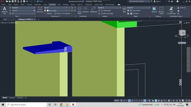
Draw the roof of thickness 150mm as in figure shown and also draw a parapet wall at a height of 600mm.
Step:6
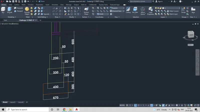
Draw a rectangle of dimension 230X600, below the floor level.
Draw a rectangle of dimension 330X400, below the first level.
Draw a rectangle of dimension 430X400, below the second level.
Draw a rectangle of dimension 670X300 below the third level.
Trim the unnecessary edges and form the structure.
Then draw a line of 230mm at GL, offset the line to 50mm below the GL
Offset the other line to the distance of 2100 to above.
Draw the door shade.
Step:7
Final outcome is as shown in the figure.
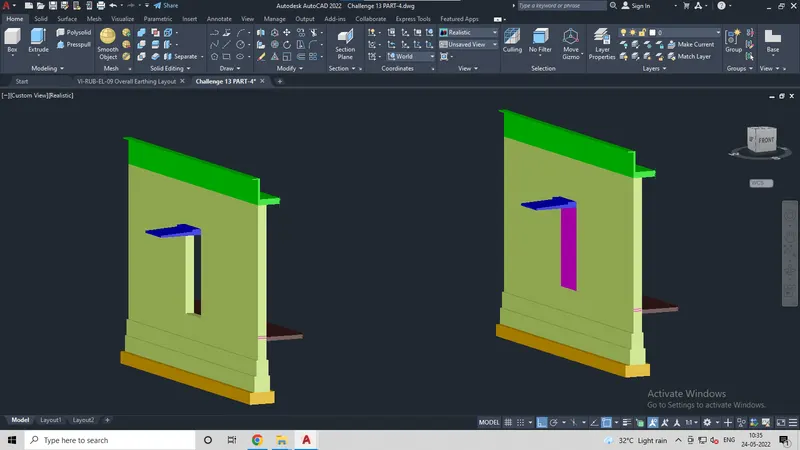
For the 3D view of the same use extrude command and extrude the 3D wall structure at a distance of 7500mm.
Add the door opening just by adding rectangle at the door location that is shown in the plan view.
Step:8
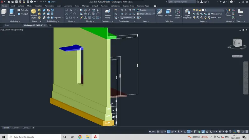
Add dimensions to the 3D structure formed.
Step:9
Rendering is done by adding materials to the 3D view.
Adjust the texture and lights of the 3D structure.
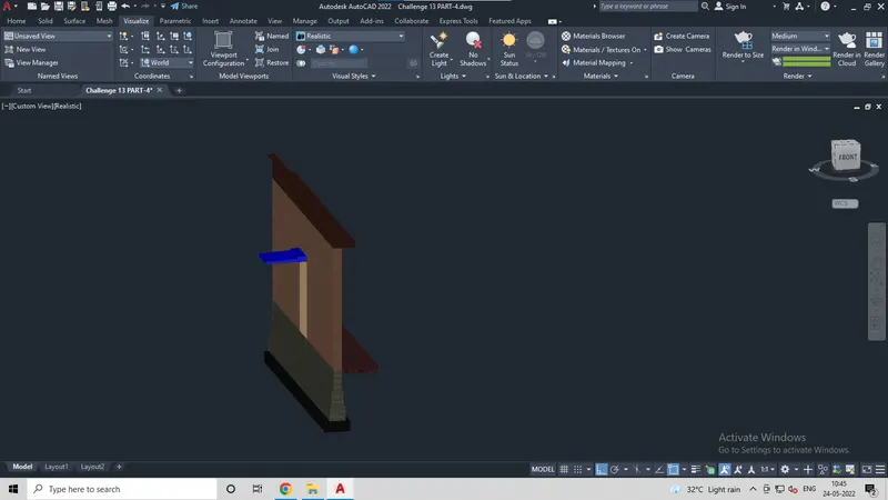
Result:
Thus, after assembling each and every part the final product which is the 3D model of the building with spread footing is obtained with indicative dimensions and materials are added to the same and a rendered view of the model is presented.