Creating 3D Isometric view of various structural elements in AutoCAD
AIM-1:
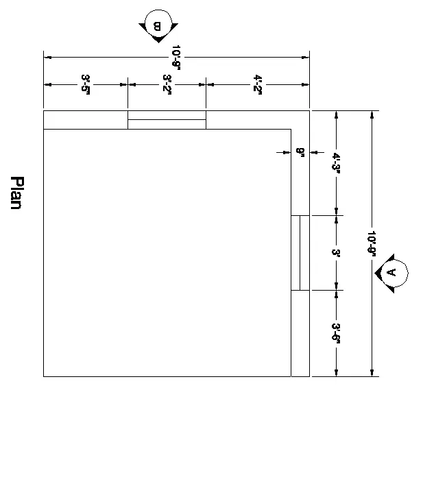
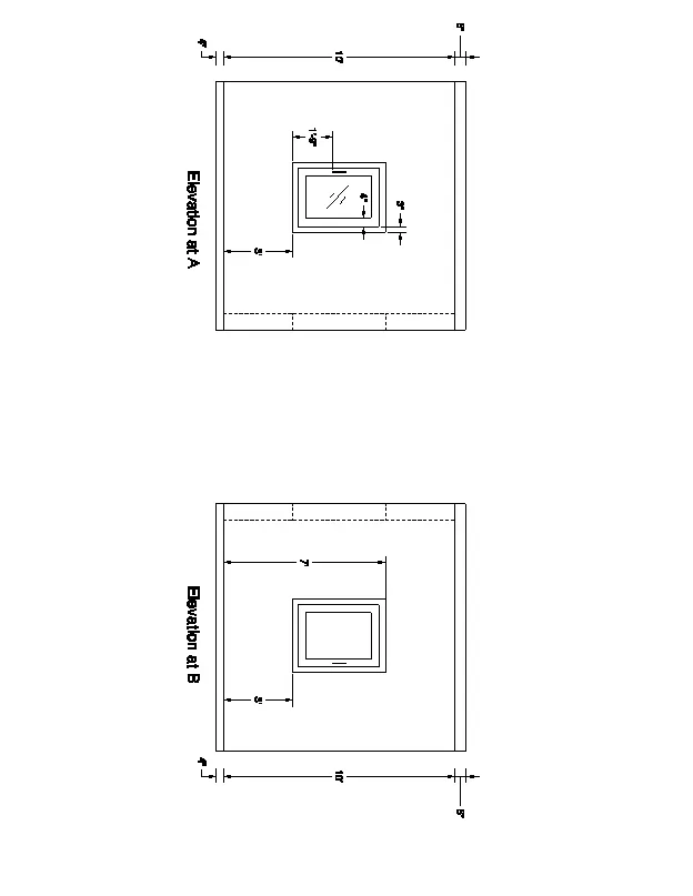
. Create a 3D Isometric View of the building with plan and elevation given.
PROCEDURE:
STEP-1:
- Open new drawing file in autocad
- set units as engneerig and set dimentions in inches 0'0".
- set limmax as 50',50'.
- set the display as in 3d modeling.
step-2:
- select the line command and draw the lines in required aspects in isomatric view.
- draw a rectangle in dimention of 10'9"X10'9".
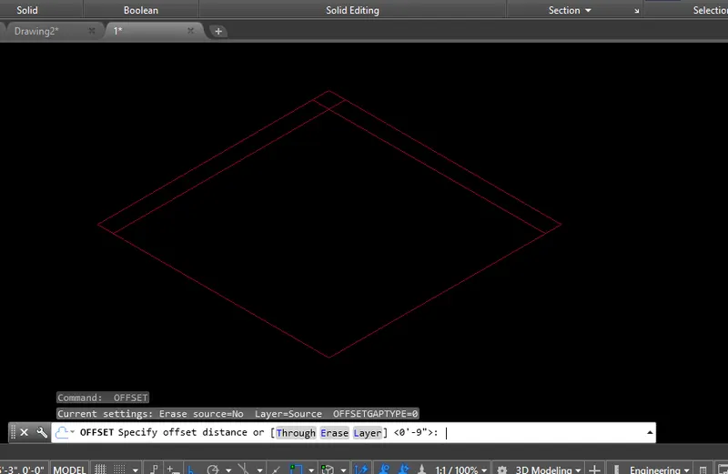
- offset the above mention lines into 9" distance.
- provide the window cutting places with using offset command.
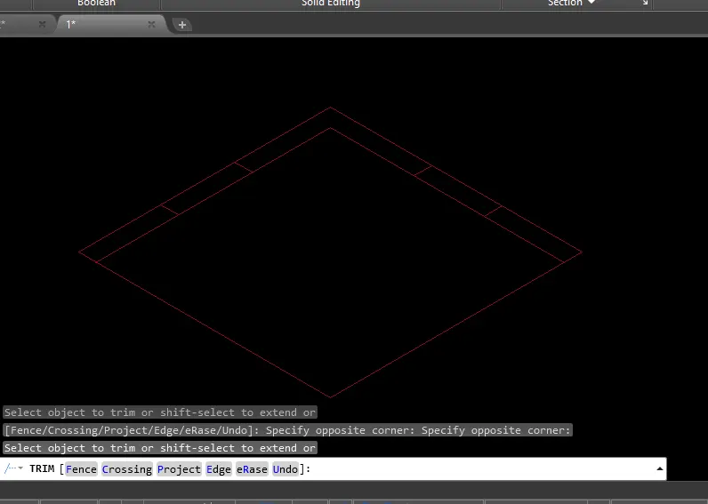
- using BOUNDARY Command make that places in to region in require layer prefered.
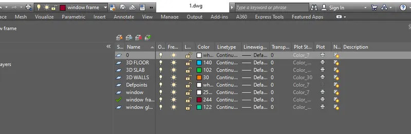
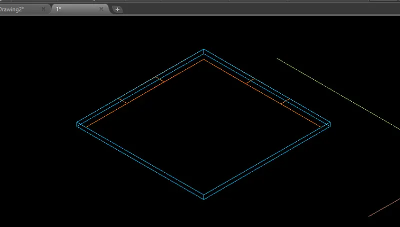
- extrude floor thickness as a 4" and after that extrude the wall partions in required height.
- provide wall height of 10' ecxcept window projecte places
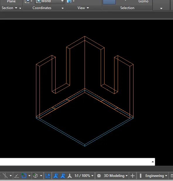
- after that window palaces provide 3' height after that leave 4' of height for window continow the wall above the window till 10' as equal to side walls.
- using UNION command all walls in region to combine.
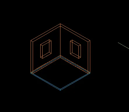
- convert screen presence as a shadeed frame.
- using UCS command place X-Y place in walls and design the window in required portion.
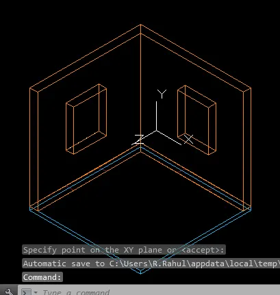
- Draw the window dimentional reference recangle copy that to another plae in screen and take offset for frame in window reference rectangle draw the anothe rec in the rectaangke with 4" offset rec.
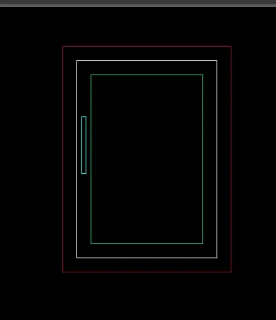
- place the every rectangle in require layer to place because we can do any custamize things things do indivisually
- deferent layer can help you to be deferent calour the element in window design.
- using BOUNDARY command region the every element in in prefered layer.
-
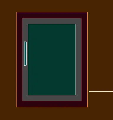
- place that window by using MOVE command.
- follow the same procedure to the another window.
- provide dimentions by the command of DIMLINEAR.
- with help of UCS command.
RESULTS:
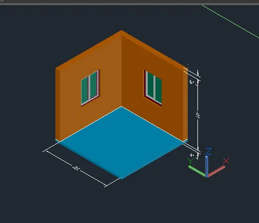
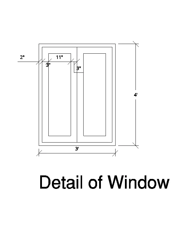
AIM2: Create the 3D View of the Building Façade as given in the plan and elevation. Also, see the detail of the window.
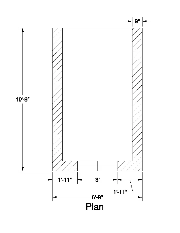
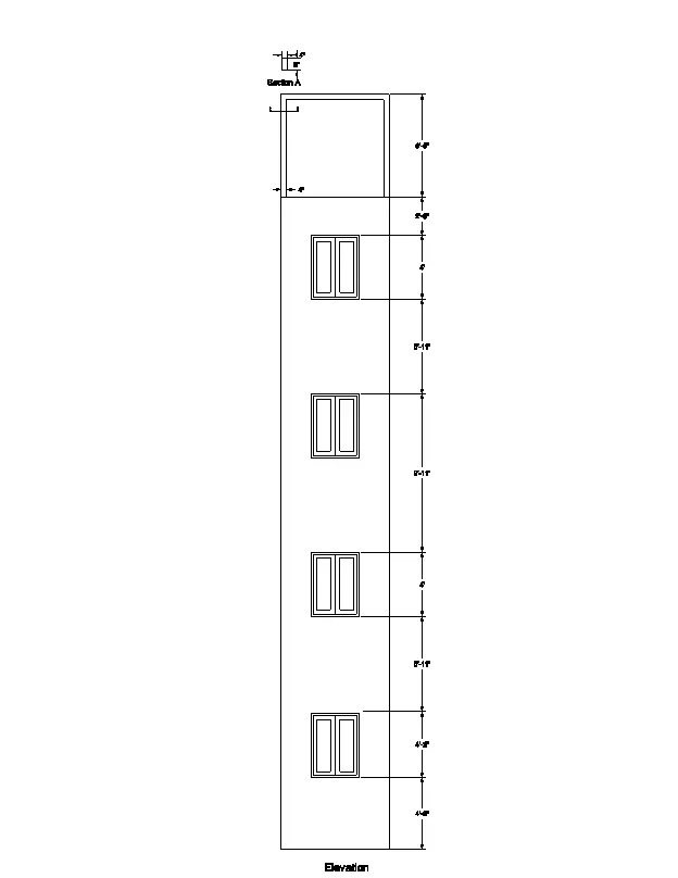
PROCEDURE:
STEP-1:
- Open new drawing file in autocad
- set units as engneerig and set dimentions in inches 0'0".
- set limmax as 50',50'.
- set the display as in 3d modeling.
step-2:
- using line command draw a plan with reference in given quesions.
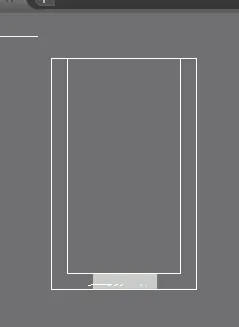
- using BOUNDARY command region the walls in required regions selected in layers
- after that EXTRUDE the region elements till the height of 44'.
- except window projected places to leave space for windows.
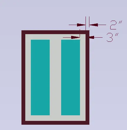
- after draw the windows seperately with given dimentions. affter place ucs ZX plain As a XY plain.
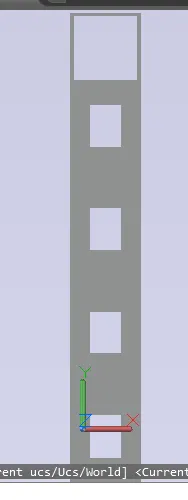
- design the windows with given dimentions and provide required fields that required elements.
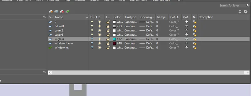
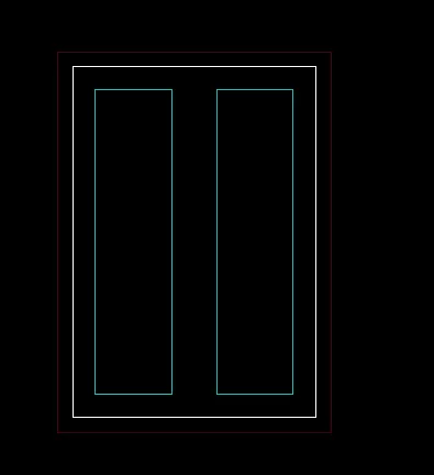
- place the windows in before except extrude places in walls.
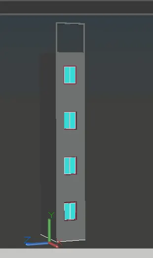
- using DIMLINEAR command apply the dimentions.
RESULTS:

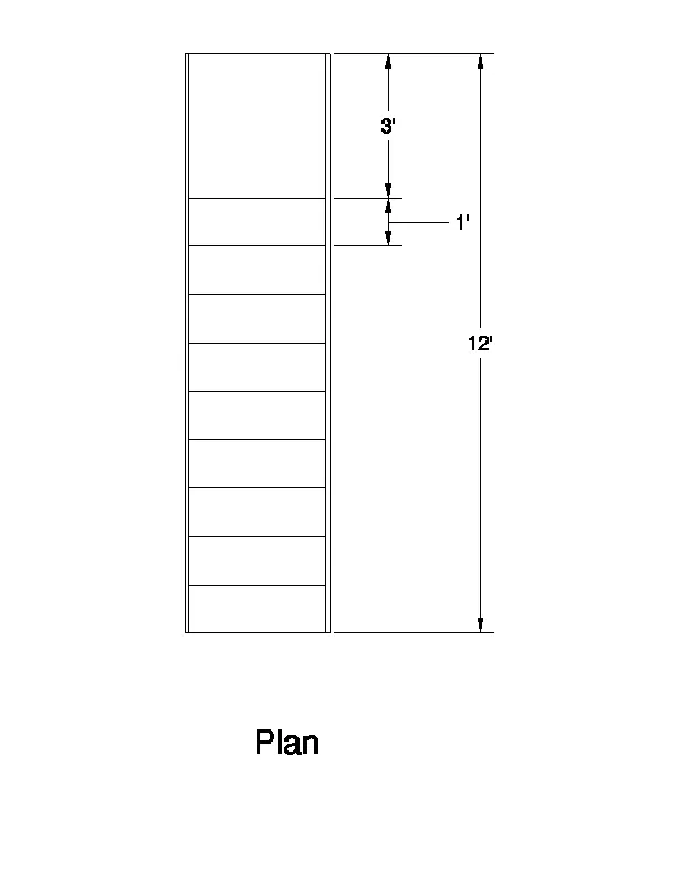
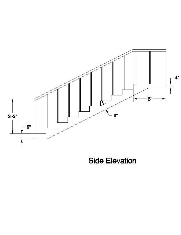
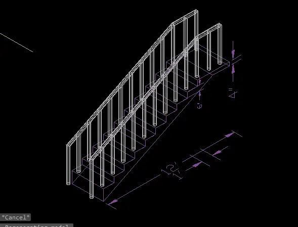
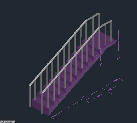
AIM-3:Create the ismoteric 3d view of a stair with railing as shown in the plan and elevation. Assume the size of the balustrades and the hand rails.
PROCEDURE:
STEP-1:
- Open new drawing file in autocad
- set units as engneerig and set dimentions in inches 0'0".
- set limmax as 50',50'.
- set the display as in 3d modeling.
step-2:
- select the line command draw like mention below with reference of given dimntions.
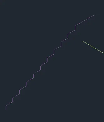
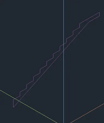
- region whole element after that extrude that whole element into 3' of distance.
- region element with the BOUNDARY command.
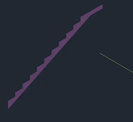
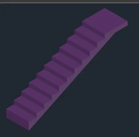
- now draw the balustrades and hand rails using line,trim, extent , pline and sweep.
- place the circles besides of stairs for balustrades.
- draw a circle in both the sides of a stair and extrude that circles in 3'2" height .
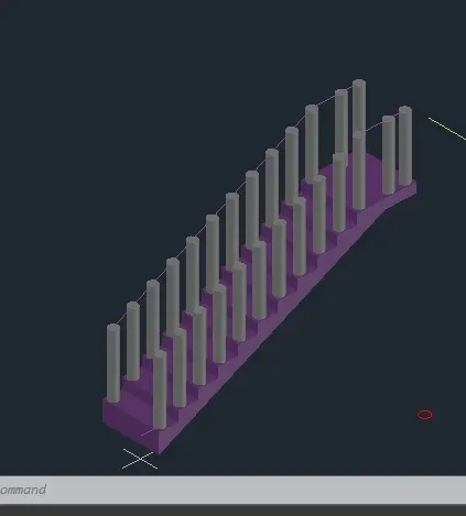 \
\- draw a PLINE above the balustrades like mention in above drawing.
- using SWEEP command draw a balustrades in above the vertical rods
- ENTER SWEEP < SELECT CIRCLE < SELECT PLINE WE GET THIS,
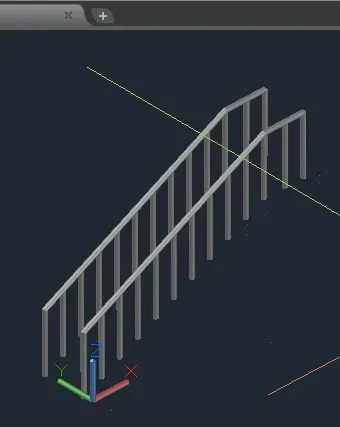
- apply the dimentions by DIMLINEAR command
RESULTS:
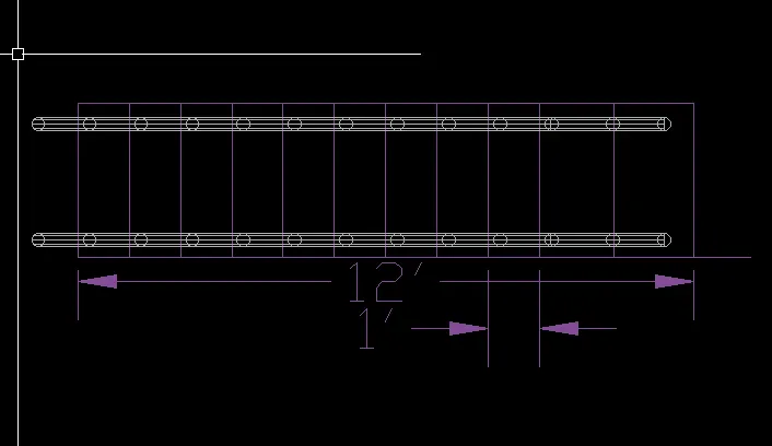
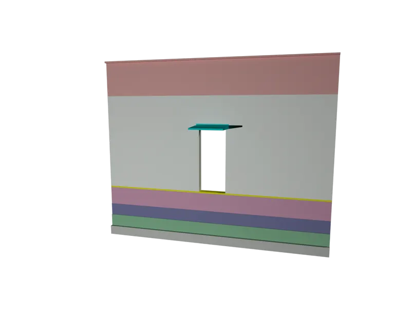
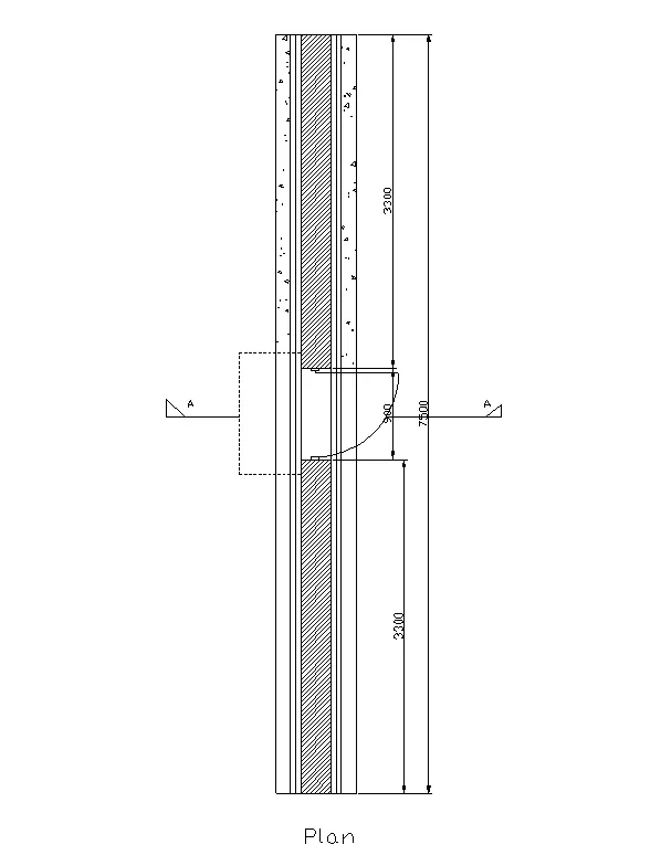
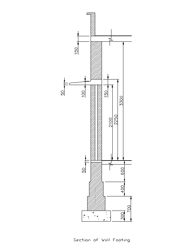
AIM-4:Create the 3D view of a Wall with spread footing . Create the Door opening only. Assume the size of the parpaet and the coping. See the plans and elevation for the details. Also, create a rendered view of the model with materials as of your choice.
PROCEDURE:
STEP-1:
- Open new drawing file in autocad
- set units as engneerig and set dimentions in inches 0'0".
- set limmax as 50',50'.
- set the display as in 3d modeling.
step-2:
- select line command and draw 1st rectangle each element draw a each leyer select like p.c.c is in 1 layer .footing all in 1 layer wall is in 1 layer.
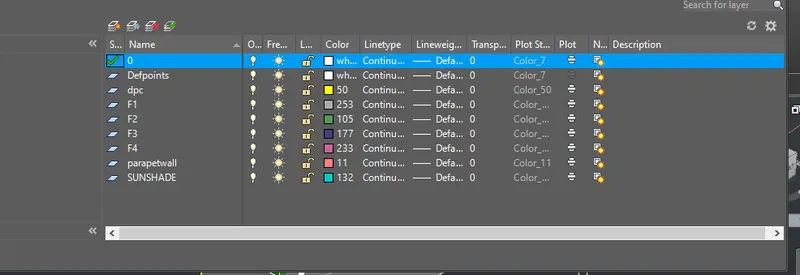
- using line command draw every footing drawings.
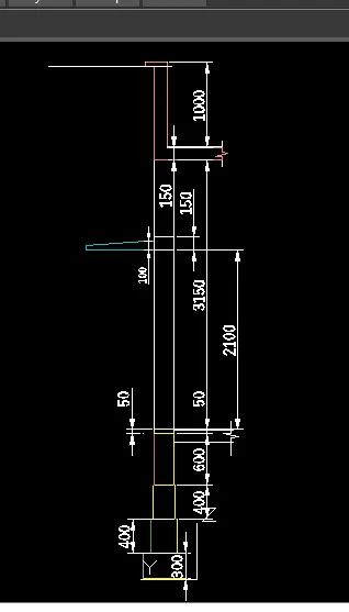
- draw every rectangle in each layer like above mention
- using UCS command select z-plane as a y-plan after that add dimlinear to every element.
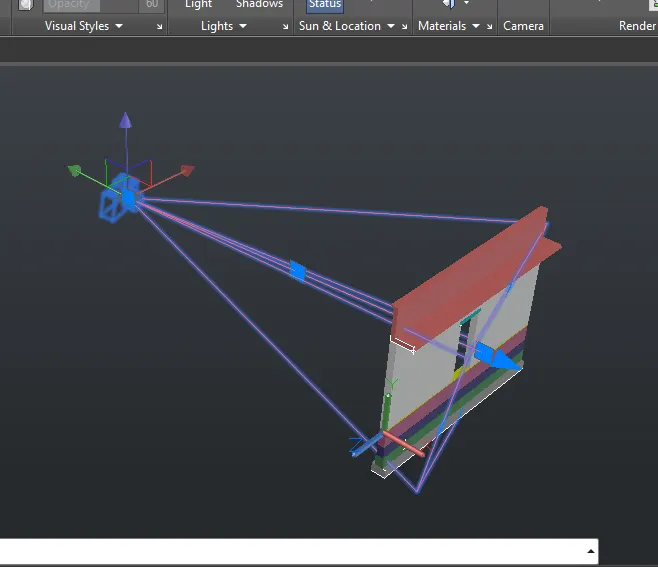
- add cemera from ribbion < visuvalization < cemera.
- set cemera name as CAM-1, set lens as 20mm , cam height -4000mm and photography.
- add leighting is it natural lighting is on are else set a leight focus through a object.
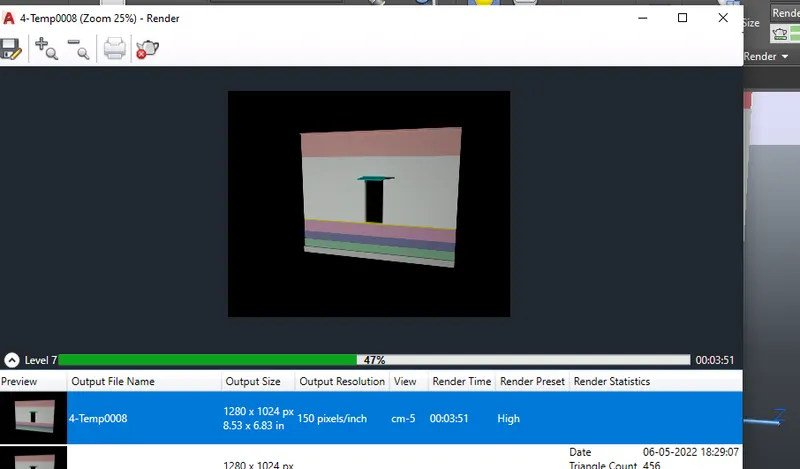
- after that render the object.
RESULTS: