Creating 3D Isometric view of various structural elements in AutoCAD
ANS.1.
AIM :-
To create the 3D isometric view of the building with plan and elevation given using AutoCAD
INTRODUCTION :-
Here commands used as follows.
Line
Rectangle
Trim
Move
Explode
sweep
Extrude
Dimlinear
Boundary
3dOrbit
3drotate
Region
UCS
Block
PROCEDURE :-
Start AutoCAD and then type UN to enter the units in architectural form
Type limmax and set the maximum page size.
Change the work space setting from drafting and annotation to 3D modelling
Then create the layers as per the requirement
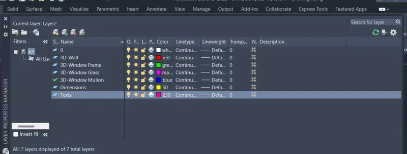
After creating the layer select the layer 3D wall and then draw a plan
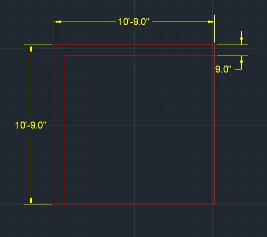
Draw a rectangle of dimension 10'9" x 10'9".
Then offset from inside that drawn rectangle to a distance of 9 inch
Then explode the created rectangles
Delete the left and bottom lines and join them to the edges.
Use the dimension tool to dimension the plan
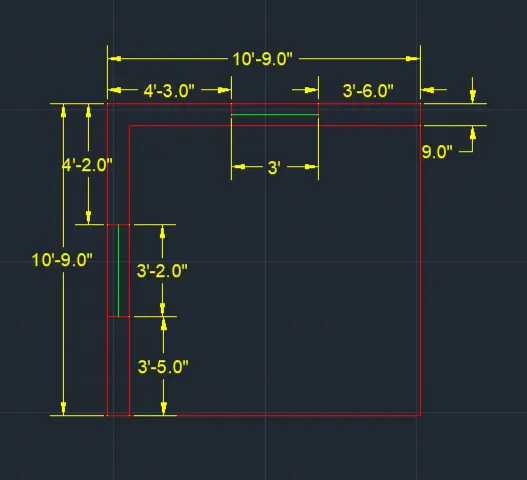
Now change the layer to 3D window frame and then draw window of dimension 3 feet 2 inch at top and 3 feet on right side.
Now to create the 3D view change the view back clicking on the home button
Type ucs and set it as world
After that type bo command to create the boundaries of wall
Extrude the boundaries of the wall the height of 10 feet 10 inches
Select all the walls and group them using group command
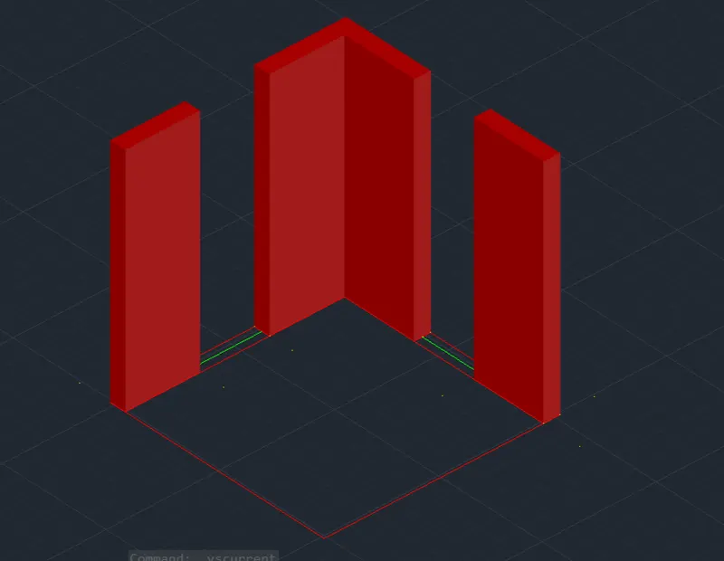
Now draw rectangle at both the windows
Used boundary command to make boundaries to them
Extrude the rectangles drawn to height 3 feet 4 inches
Again raw rectangle set the top of both window openings and again create boundaries upon them
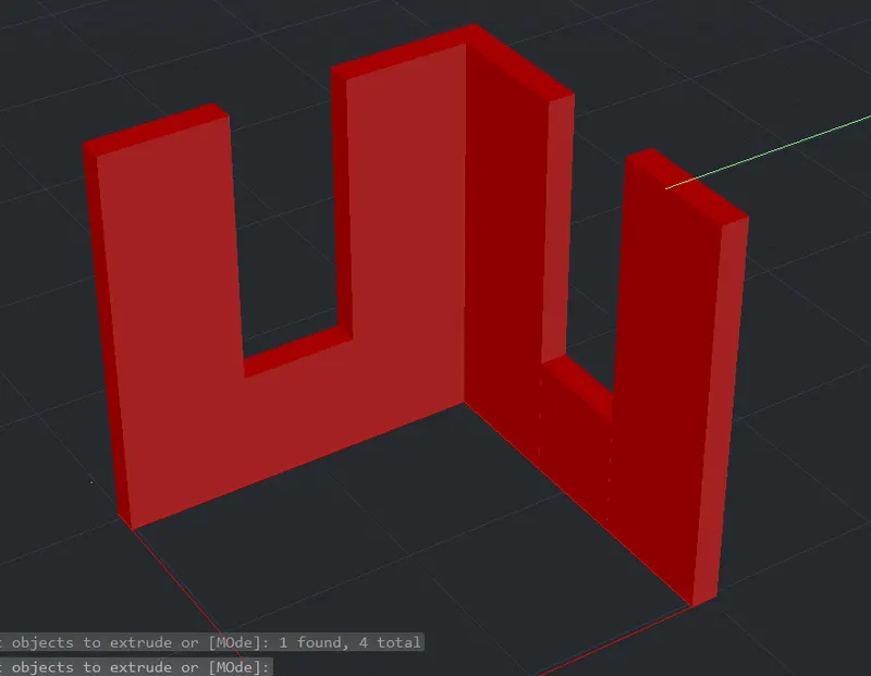
Extrude the draw on rectangle at the top to meet the window requirements
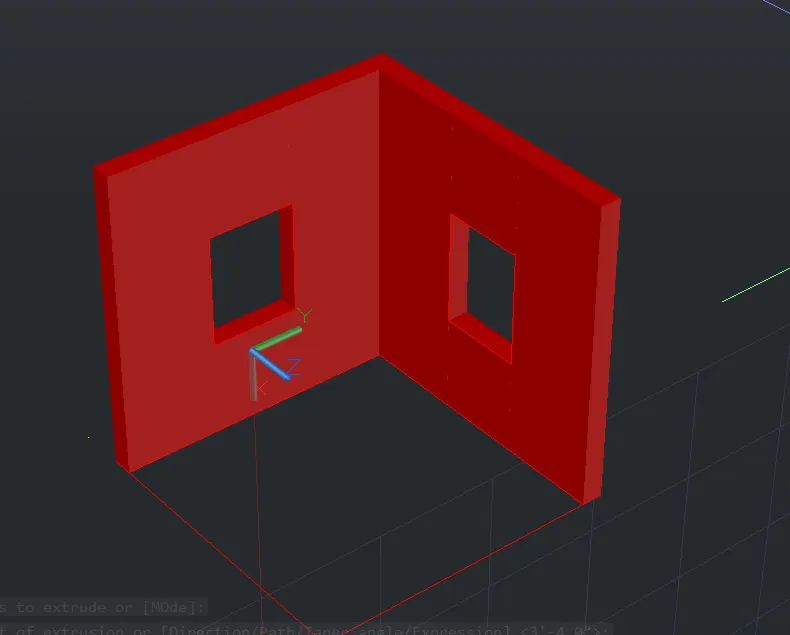
To create the window first change the current layer into 3D window frame
Then type ucs and select the face of the three inch window
Then draw a Rectangle of dimension 3 feet and 4 feet
Outside the rectangle to inside a distance of 3 inches
Again offset the created offsetted rectangle to 4 inches inside
Use the boundary command to create boundaries on the frame and then select the subtract command to subtract the region
Do the same for window mulion and window glass
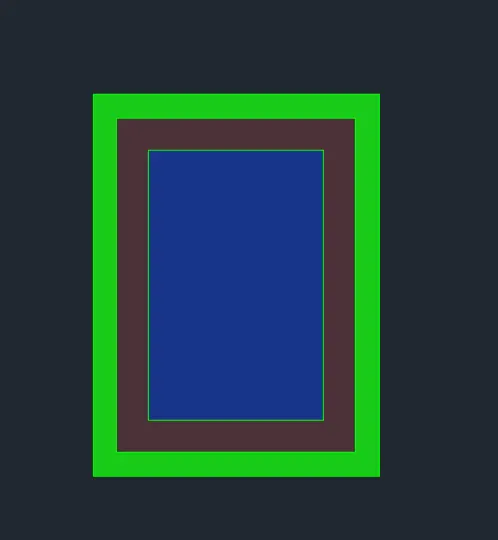
Change the view cube by clicking on the home button.
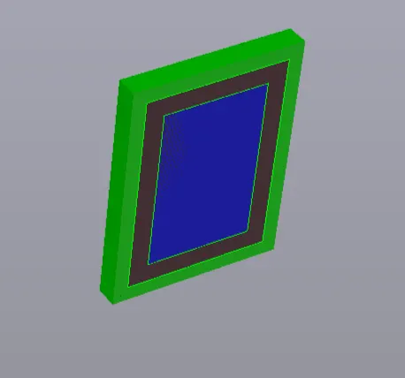
After that attach both the drawn Windows in the drawn figure
To create the floor select the floor and then provide it a layer and enter okay.
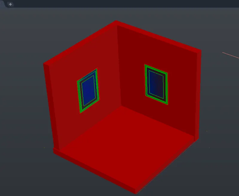
RESULT :-
Created figure is attached below :-
ANS.2.
AIM :-
To draw the 3D window facade As given in the plan and elevation
INTRODUCTION :-
Here commands used as follows.
Line
Rectangle
Trim
Move
Explode
sweep
Extrude
Dimlinear
Boundary
3dOrbit
3drotate
Region
UCS
Block
PROCEDURE :-
Start AutoCAD and then type UN to enter the units in architectural form
Type limmax and set the maximum page size.
Change the work space setting from drafting and annotation to 3D modelling
Then create the layers as per the requirement
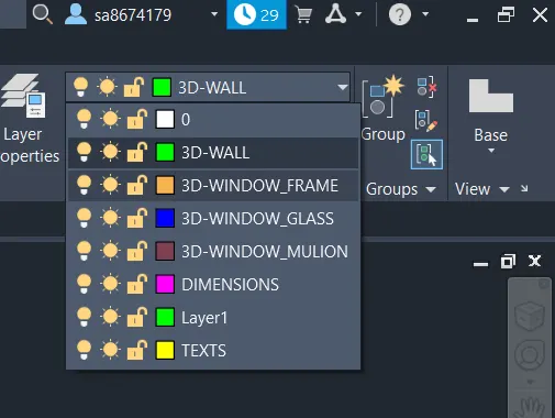
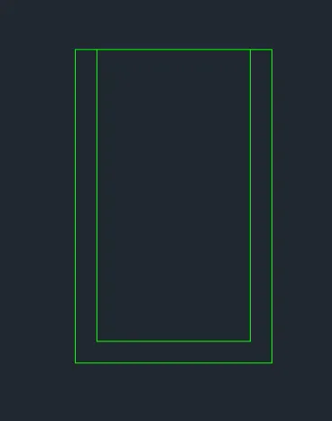
Now to create a 2D plan view
Draw rectangle of dimension 6'9" x 10'9".
Then offset the created rectangle from inside to a distance of 9 inch
Now explode the rectangles and then delete the top line and stretch the top line to the edges
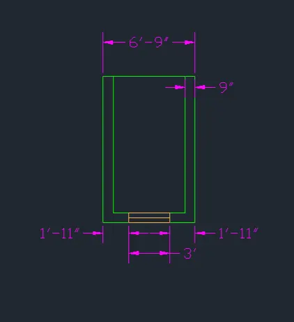
To create the 3D window frame change the layer to 3D window frame and create a Window opening of dimension 3 feet wide.
At the dimensions by using the dim command in the dimension layer
Change the Bluetooth 3D by clicking on the home button of the view cube and set the ucs as world
Create the boundaries of the walls using the Bo command
Extrude the boundaries then to height of 10 feet 10 inches
After that select all the walls and group them together by using group command
Then delete the window line
Change the view to realistic
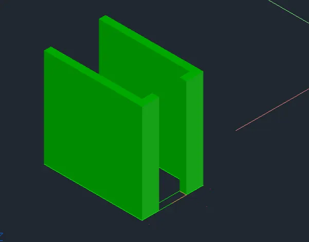
For the creation of Windows
Change the layer to 3D window frame and type the ucs and select face having 3' wide window.
Draw rectangular dimension 3 feet and 4 feet
Offered the rectangle from inside to a distance of 2 inch
Then again offset it to inside a distance of 3 inch
Draw Centre line and offset 1.5 inch in right than 1.5 inch in right
Then trim the unnecessary lines
Select the boundary command and click on pick points click the inside the window frame area and enter
Then select the subtract command and select the bigger region then select the smaller region and subtract them.

Same procedure can be applied for Windows mulion and glass.
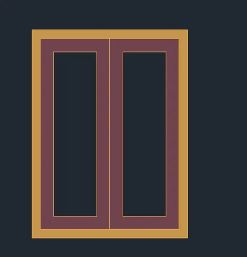
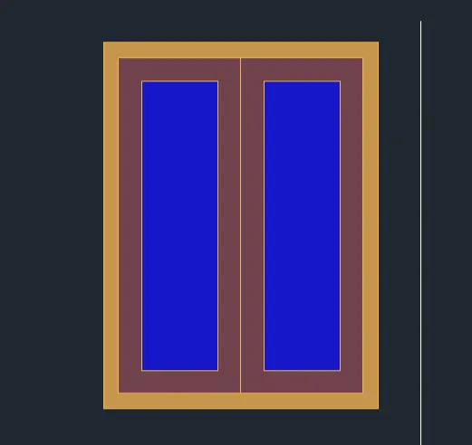
Change the view into 3D by clicking on the home button on viewcube
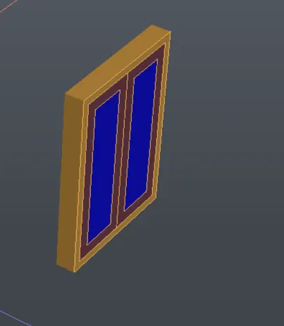
Then change the face by using the ucs command to the world and then place the window in the required area
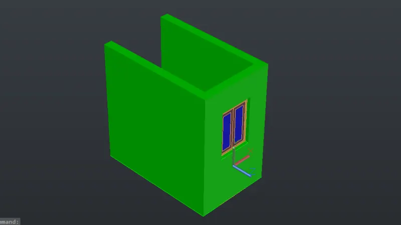
Use the group command to group the created figure and then select the drawn figure.
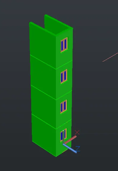
Use copy command and copy it three times above the ground layer.
To create the top part of the drawing draw a line of 6 feet 5 inch height from top and 4 inch offset It Inside.
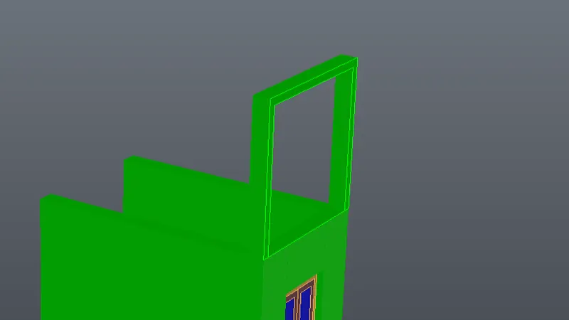
Extrude the line 9" as given.
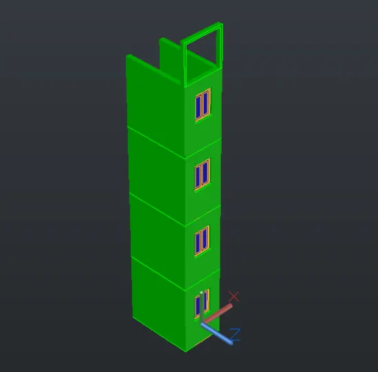
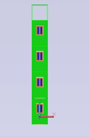
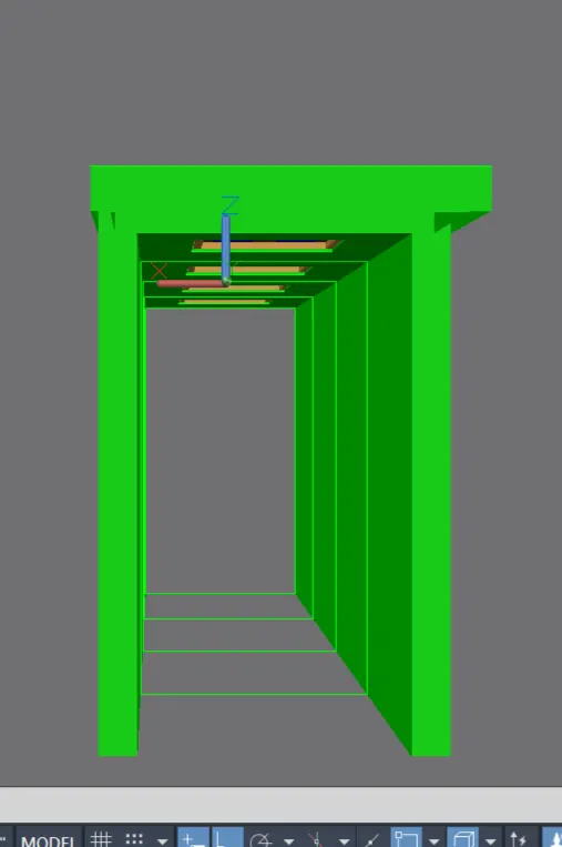
RESULT :-
Created figure is attached below
ANS.3. :-
AIM :-
To draw 3D view of stair with railing as shown in plan and elevation
INTRODUCTION :-
Here commands used as follows.
Line
Rectangle
Trim
Move
Explode
sweep
Extrude
Dimlinear
Boundary
3dOrbit
3drotate
Region
UCS
Block
PROCEDURE :-
Start AutoCAD and then type UN to enter the units in architectural form
Type limmax and set the maximum page size.
Change the work space setting from drafting and annotation to 3D modelling
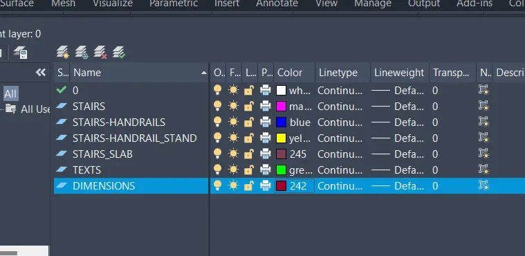
Then create the layers as per the requirement
Change the current layer to Stairs.
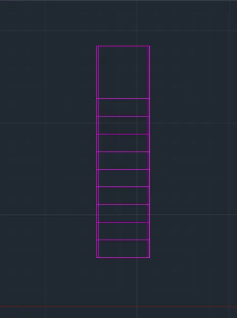
Then draw, a rectangle of dimension 3' x12'
Then explode it
use offset tool to offset the side edges by 1"
again offset the bottom edges to up 12 times to a distance 1' using offset multiple option.
Change the view to 3d by clicking on home button on viewcube
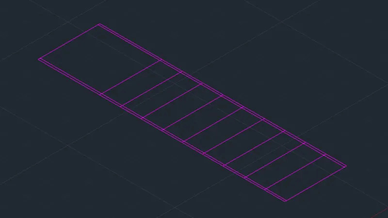
Then ,
Set the UCS at right
Draw a line of length 6" vertically and horizontally1'.
Repeat the same process 12 times for drawing 12 steps.
Draw landing of 3'
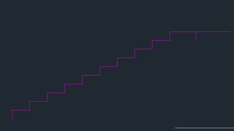
Draw a line of 1' at bottom step and 6" at the top right edge of landing
Draw a slab joining them .
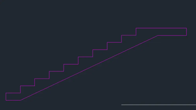
Select it and use BO command to make region
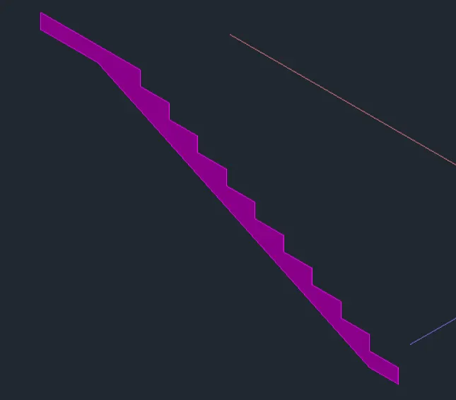
Extrude the face of the stair by 3'
Change the view to REALISTIC
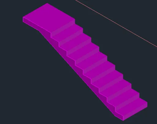
For drawing of railings , first change the layer to Stair Railings
then, draw a circle of dia 1' .
Extrude the circle to height ot 3'.
Copy the railing as required for both of the sides.
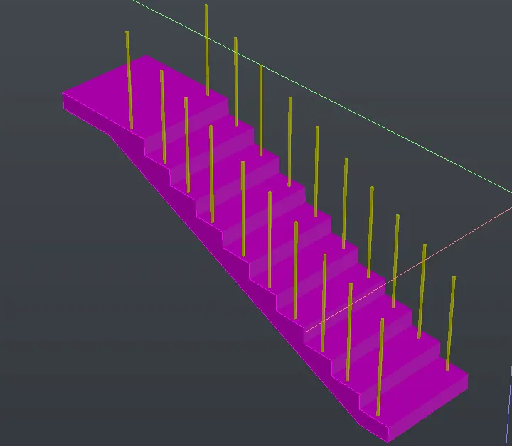
Then change it to front view
Also change the UCS to front
Then, draw a circle of dia 2" on top of first railing
Create the region using BO command
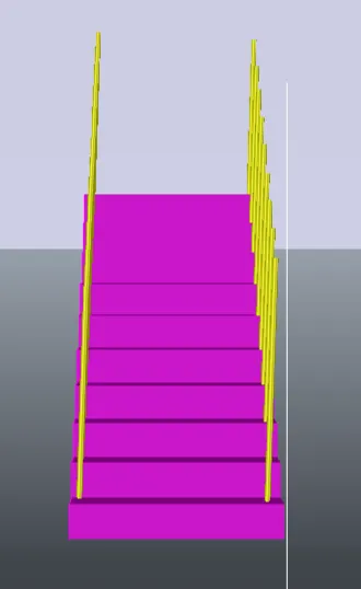
Then, draw a polyline on both the side of railing connecting every railing
After that use SWEEP command , and select the baseline as polyline
Handrails are created on the selected layer.
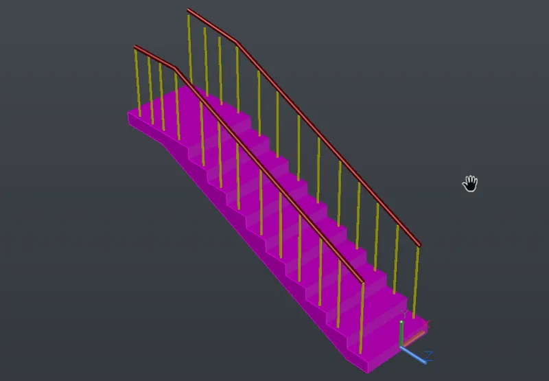
RESULT :-
Created figure is attached below :-
ANS.4.
AIM :-
To draw the 3D view of wall with spreadfooting as shown using Autocad software
INTRODUCTION :-
Here commands used as follows.
Line
Rectangle
Trim
Move
Explode
sweep
Extrude
Dimlinear
Boundary
3dOrbit
3drotate
Region
UCS
Block
PROCEDURE :-
Start AutoCAD and then type UN to enter the units in architectural form
Type limmax and set the maximum page size.
Change the work space setting from drafting and annotation to 3D modelling
Then create the layers as per the requirement
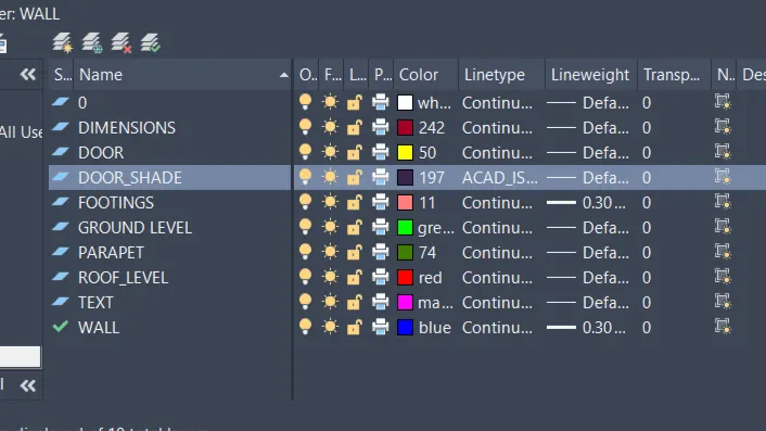
Change the layer to wall
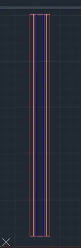
Draw rectangle of dimension 670 X 7500
Then offset the rectangle inside 120
Again ofsett the offset rectangle inside 50 mm and 50 mm
Explode the rectangle and then delete the top and bottom edges.
Extend all the edges from top and bottom and then select the lines and change their layers
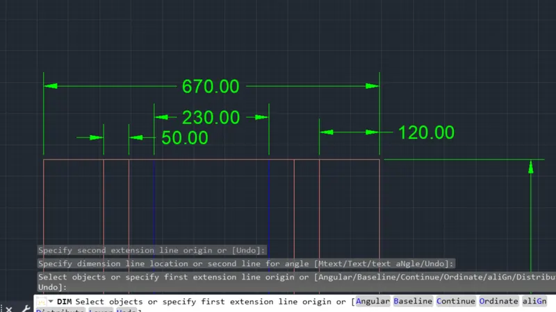
Use dimension to dimension the created figure by changing the layer
Dimensioning is been done by dimension tool
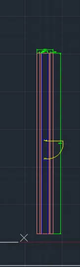
To create a door block
First draw rectangle of dimension 50 x 100 and draw another rectangle of dimension 50 X 50
After that draw a line of length 850 from the edge and draw and arc line for the door swing
Now convert the door into a block and insert it as per the required area into the figure.
For creating the elevation view
First click on the front view of the view cube then change the ucs to friend and change the current layer to ground level
Now draw the bottom length a line as per the requirement and then offset it to 25 mm bottom and again ofset it to distance of 100 mm
Then change the layer to roof level and draw a roof of thickness 150 mm and a paraffin wall of height 600 mm
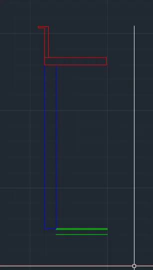
Now to create the footing layers
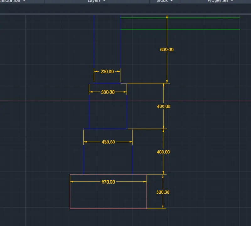
First draw a rectangle of dimension 230 x 600 below the floor level
And below it draw a rectangle of dimension 330 x 400.
Again draw rectangle of dimension 430 X 400 below the second level.
Change the current layer to putting and then draw a rectangle of dimension 670 X 300 below the Third Level
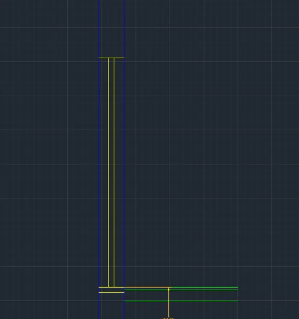
To draw the door first change the layer into door
Then draw a line along the length of the door of 230 mm at the ground level and then offset it to a distance of 50 mm below the ground level
Again offset the line to distance of 2100
Then from the centre line draw a line joining both the lines and offset 25 mm both the sides.
To create the shade first draw a line using the line tool and change the layer into the door shade layer , then draw the shade.
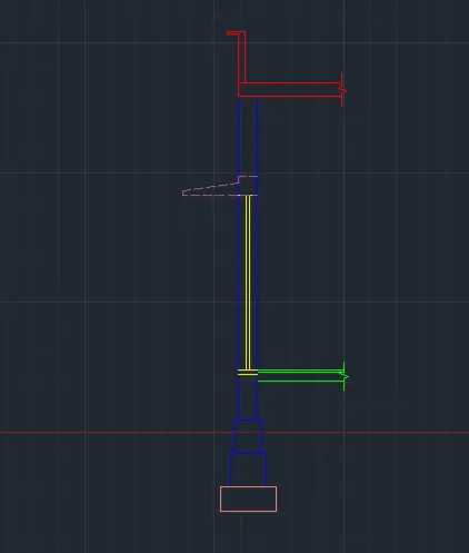
Then change the view to 3D view or realistic view
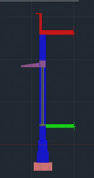
Select individually the layers and then select the created component and make them region using boundary command.
Then to extrude the created figure
Select the figure and then select the extrude command and extrude them at a distance of 7500 mm.
The door and door shade are also selected by creating a rectangle by changing the face and then subtract them using subtract command to make them appear like a door and door shade.
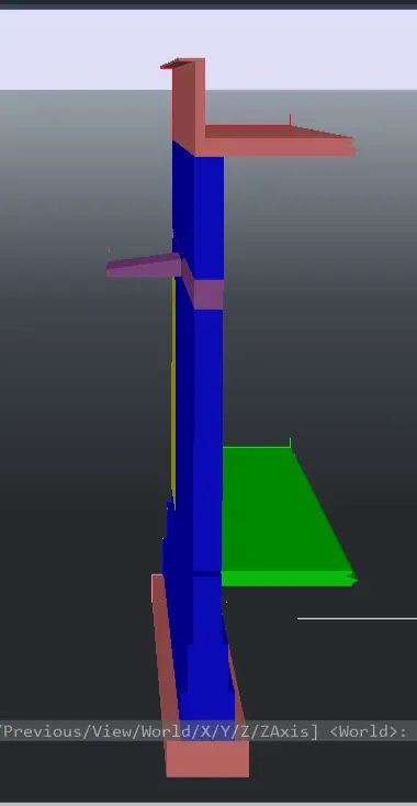
Realistic view of the created figure
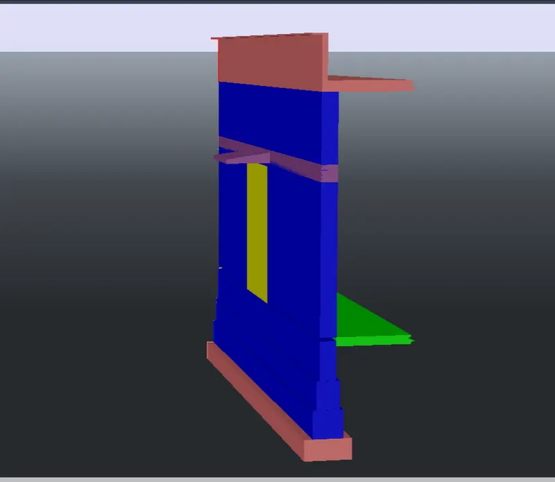
RESULT :-
Created figure is attached below :-
NOTE :- WHILE RENDERING THE CREATED FIGURE , AUTOCAD SOFTWARE WAS KEEP ON CRASHING .I TRIED IT SEVERAL TIME BY ALSO REINSTALLING THE SOFTWARE BUT IT KEPT ON CRASHING AND ALSO THE LAPTOP PROVIDED FROM SKILL LYNC GETS HANGED EVERYTIME ,SO I M NOT ABLE TO ATTACH RENDER FILES AS THE GIVEN LAPTOP IS KEPT ON CRASHING EVERYTIME DURING RENDERING. .