Creating 3D Isometric view of various structural elements in AutoCAD
Creating 3D Isometric view of various structural elements in AutoCAD
Jagadeep.M.M
AIM:
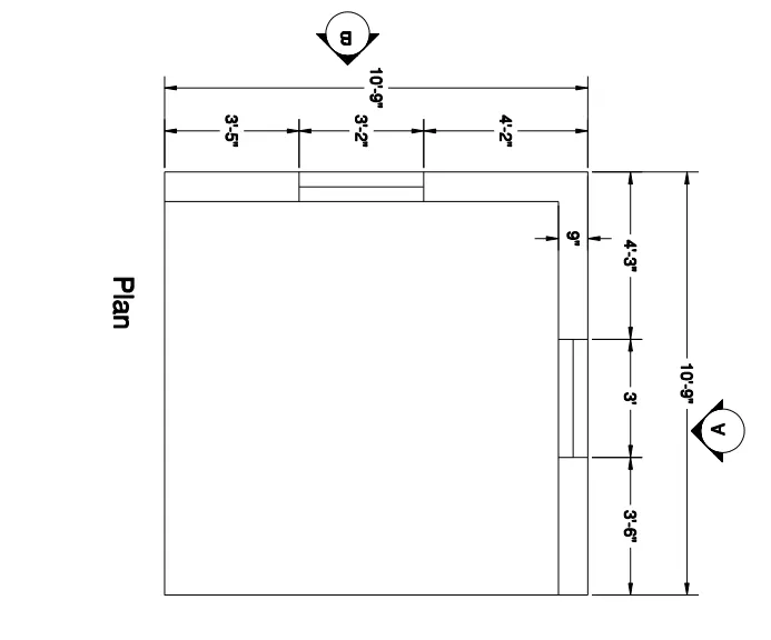
Create a 3D Isometric View of the building with plan and elevation.
PROCEDURE:
Step 1
- Open autocad softwere, type QNew incommand box,press enter.
- Click on the workspace switching & change it to 3d modelling.
- Select default setting as imperial setting.
- Drawing units setting as length=(Engineering),precision=0'0.0", Ok
- Drawing limits setting as, specify the lower left corner=enter,upper right corner=100',100',enter.
- Type the command box Dimension style manager & press enter.
- enter modify-enter primary units-unit format=Engineering, precision=0'0.0",enter Ok.
Step 2
- PLAN
- Draw the plan in top view
- create the rectangle using rectangle command size as @10'9",10'9".
- Give the inside offset of 9" wall & explode it.
- Trim the left side & bottom line.
- Then extand the line.
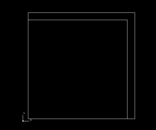
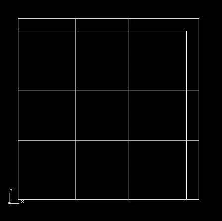
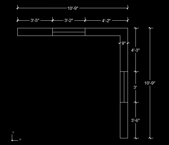
- Give the offset of 4'2" from the corner of the wall.
- Again offset of 3'2" from that line for the window.
- Similarly on the other side also offset 4'3"from the corner,again give offset of 3' for the window.
Step 3
- Trim the unwanted line & draw the window.
- Give the dimension using dimension command.
Step 4
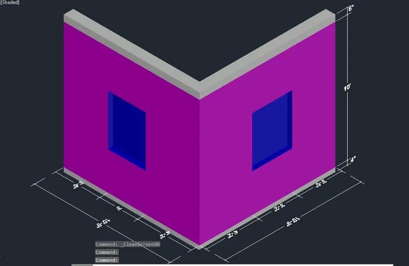
- Use the command "3do" for orbiting the view so that 3d is seen.
- Now create the region in the wall area by command "BO" for boundary.
- Now extrude the region & give the height of 10' using the extrude command.
- Now create the opening for windows & draw a rectangle over the window portion & extrude it 4' & use the move command & move it +z direction at 3'.same as another window also.
- use the polyline command draw the line below the wall & extrude it -z direction of 4" & draw polyline above the wall & extrude it +z direction of 6".
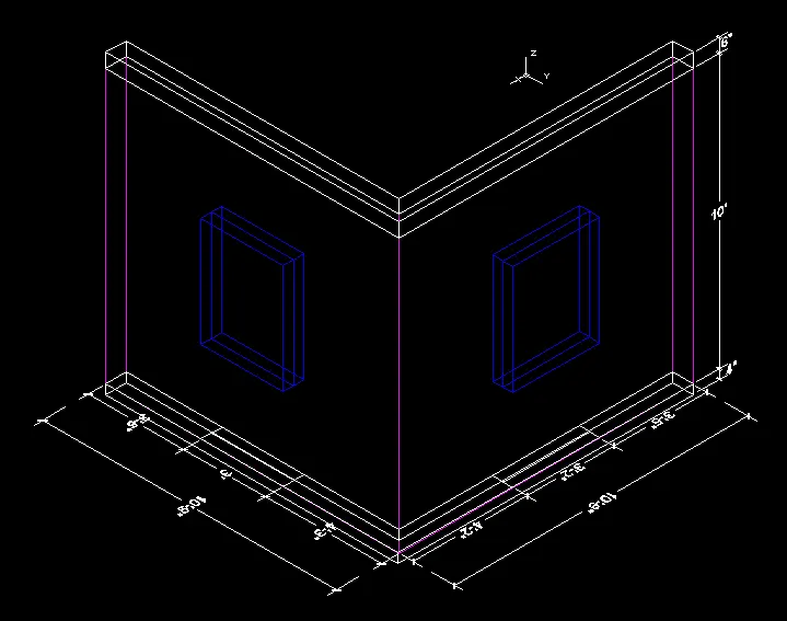
- now use the subtract command & subtract it the windows.
Result
Step 5
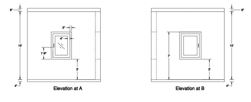
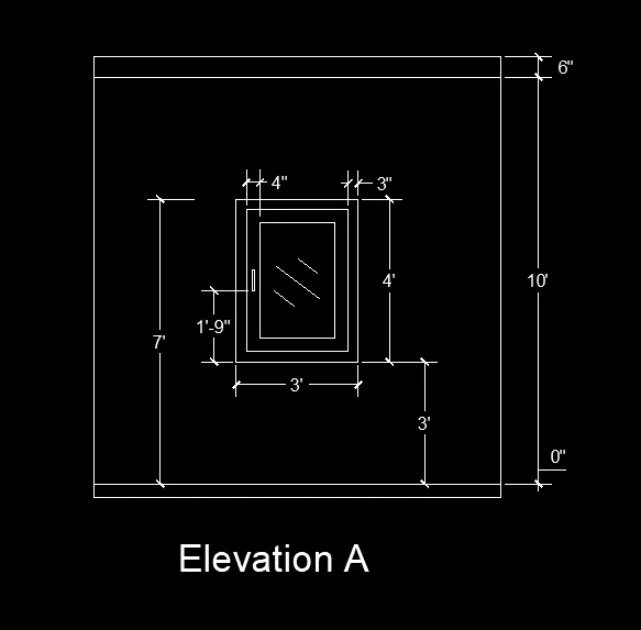
- Elevation at A
- Go to the top view & create the rectangle of 10'X10'.
- Explode the rectangle & give the offset of above 6" & below 4".
- Create the windows size as 3',4' rectangle place it the window in bottom center & move it above 3' distance.
- Give the window inside offset of 3" again give the offset of 4".
- Give the dimension & text.
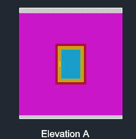
- Use the command "3do" for orbiting the view so that 3d is seen.
- Now create the region.
- use the color faces & assign the color.
Result
Step 6
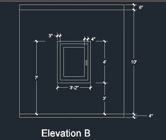
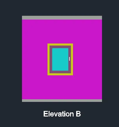
- Elevation at B
- Go to the top view & create the rectangle of 10'X10'.
- Explode the rectangle & give the offset of above 6" & below 4".
- Create the windows size as 3'2",4' rectangle place it the window in bottom center & move it above 3' distance.
- Give the window inside offset of 3" again give the offset of 4".
- Give the dimension & text.
- Use the command "3do" for orbiting the view so that 3d is seen.
- Now create the region.
- use the color faces & assign the color.
Result
Result
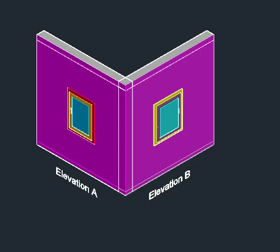
AIM:
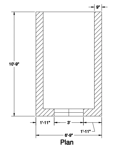
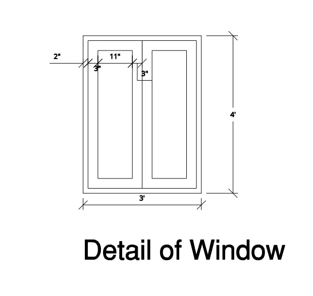
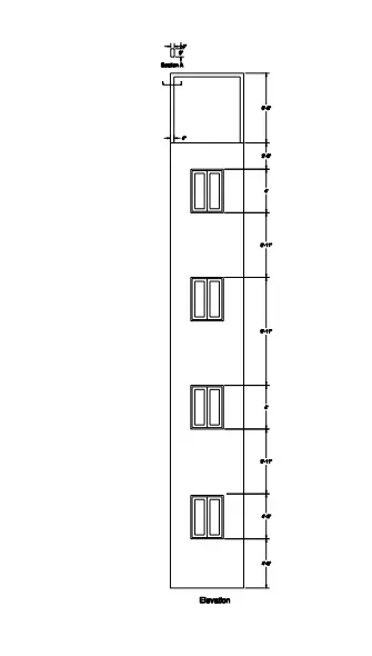
Create the 3D View of the Building Façade as given in the plan and elevation. Also, see the detail of the window.
PROCEDURE:
Step 1
- Open autocad softwere, type QNew incommand box,press enter.
- Click on the workspace switching & change it to 3d modelling.
- Select default setting as imperial setting.
- Drawing units setting as length=(Engineering),precision=0'0.0", Ok
- Drawing limits setting as, specify the lower left corner=enter,upper right corner=100',100',enter.
- Type the command box Dimension style manager & press enter.
- enter modify-enter primary units-unit format=Engineering, precision=0'0.0",enter Ok.
Step 2
- PLAN
- Draw the plan in top view
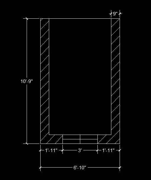
- create the rectangle using rectangle command size as @6'10",10'9".
- Give the offset of 9" of inside.
- explode the rectangle & give the offset of left to right & right to left as 1'11" both the side.
- trim the unwanted lines.
- use the hatch command & dimension command.
Result
Step 3
- Create the region using region command.
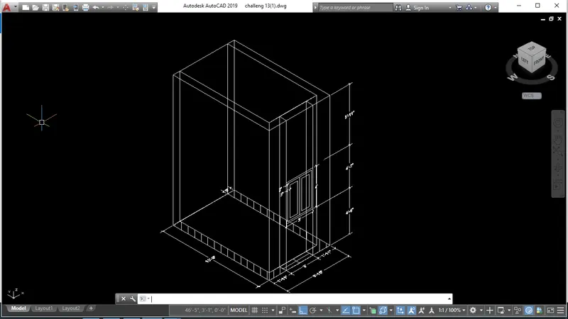
- Click on the 3d model & use the extrude command the distance will be given as 4'6",4'2",5'11",4',9'11",5'11",4',2'5".
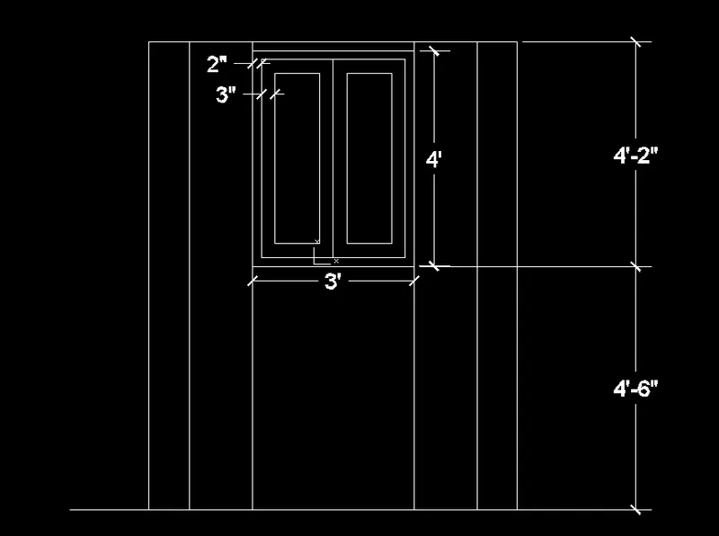
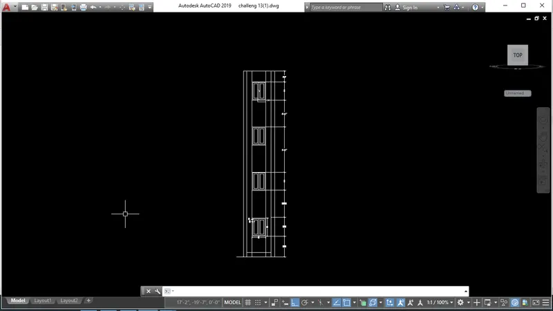
- Create the window use the UCS command, give the Face & Type the Plan.
- create the rectaangle of @3',4'.
- Give the offset of 2" of the inside rectangle.
- explode the rectangle & give the centerline of the inside rectangle.
- create the inside two rectangle of the glass frame give the 3" offset for all side.
- Trim the unwanted lines
- Give the dimension of the windows.
- dimension using dimension command.
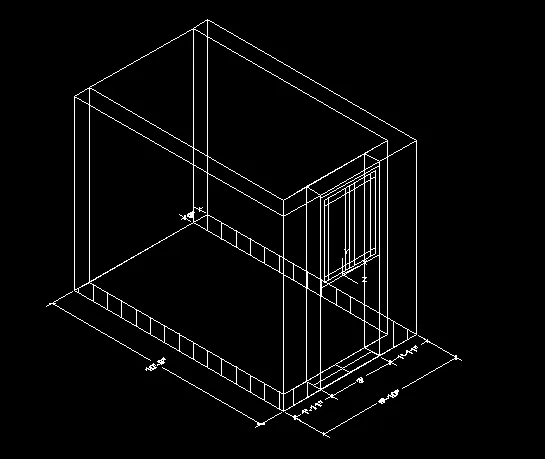
Result
- Create the top of the column shape.
- Open top view of the building, create the UCS in the corner of the building.
- Create the rectangle size of 4",9" .
- use the polyline command draw the line in rectangle corner to +z direction of 6'5" & +x direction of 6'10", -z direction of 6'5".
- use the "Sweep", press the rectangle press enter then press the polyline ,press enter.
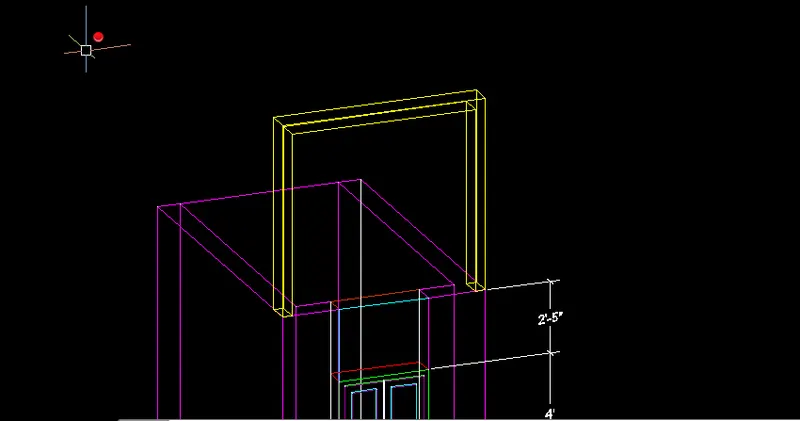
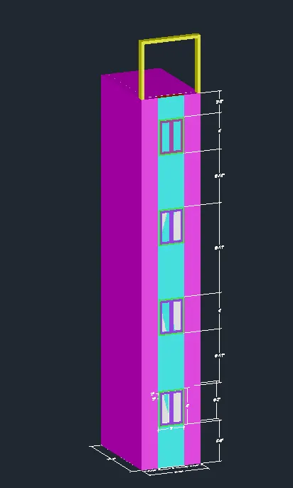
- usr the color face & assign the color.
Result
AIM:
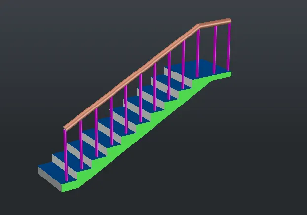
Create the ismoteric 3d view of a stair with railing
PROCEDURE:
Step 1
- Open autocad softwere, type QNew incommand box,press enter.
- Click on the workspace switching & change it to 3d modelling.
- Select default setting as imperial setting.
- Drawing units setting as length=(Engineering),precision=0'0.0", Ok
- Drawing limits setting as, specify the lower left corner=enter,upper right corner=100',100',enter.
- Type the command box Dimension style manager & press enter.
- enter modify-enter primary units-unit format=Engineering, precision=0'0.0",enter Ok.
Step 2
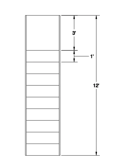
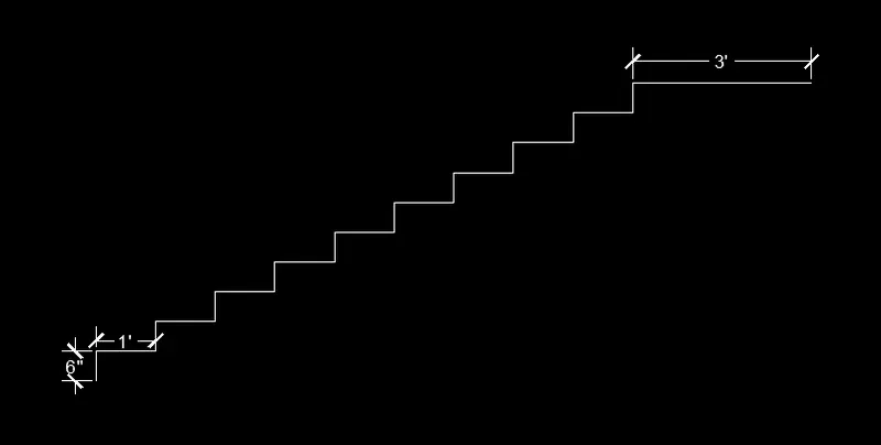
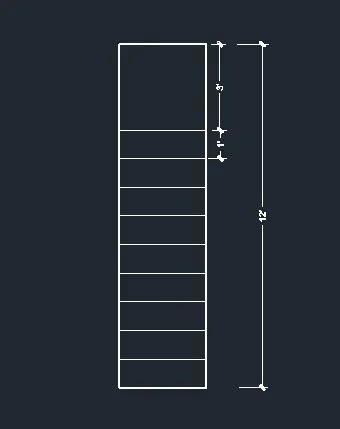
- Draw the steps in top view.
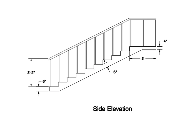
- Use the lin command rise as 6" & the thread as 1'.
- Copy the created 1st step inall steps,create the steps as 9
- Landing distance as 3'
- wasit slab thickness is 6",use the fillet command & join the corner.
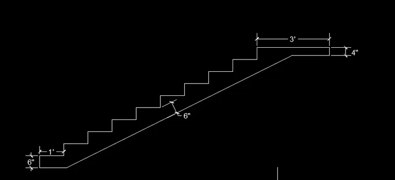
- create the region & covert 3d view.
- Extrude towards the side as 3' is taken as width of the stair case.
Result
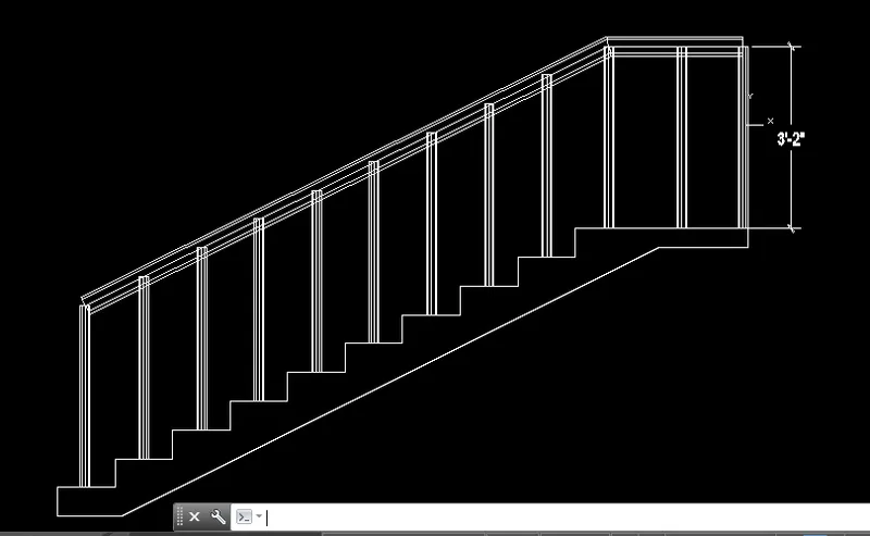
- Now create the handrail by placing the on the thread & create the circle of center dia 2"
- create the region & extrude it as 3'2" +z direction.
- Use the line command draw the line rail top place it Create the another circle raius as 2".
- use the sweep command assign the cirle in the line.
Result
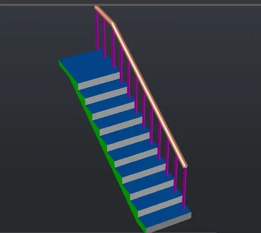
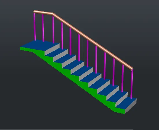
- use the color face & assign the color.
- use the "3do" orbit change the position.
Result
AIM:
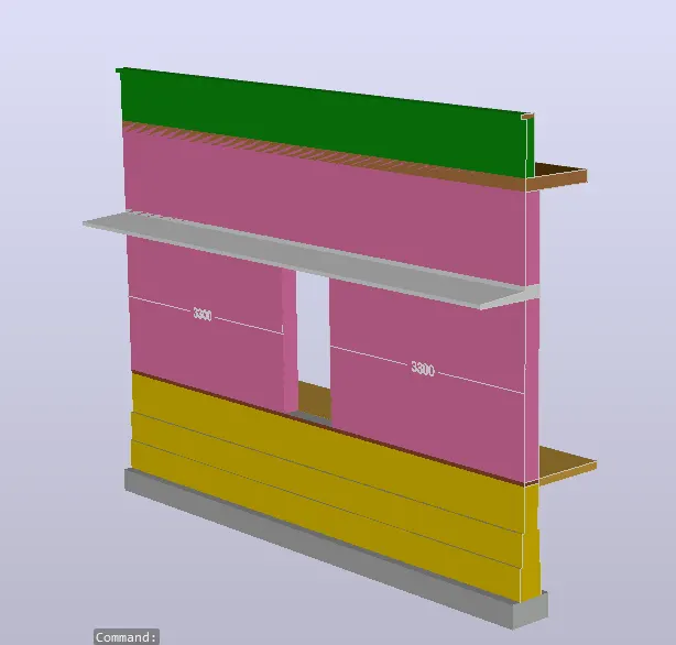
Create the 3D view of a Wall with spread footing .
PROCEDURE:
Step 1
- Open autocad softwere, type QNew incommand box,press enter.
- Click on the workspace switching & change it to 3d modelling.
- Select default setting as imperial setting.
- Drawing units setting as length=(Decimal),precision=0, Ok
- Drawing limits setting as, specify the lower left corner=enter,upper right corner=1000,1000,enter.
- Type the command box Dimension style manager & press enter.
- enter modify-enter primary units-unit format=Decimal, precision=0,enter Ok.
Step 2
- Draw the Plan in top view.
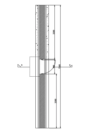
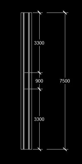
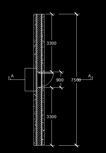
- Draw a line of 7500mm & give the offset of 230mm of wall thckness.
- Again give the offset of 35mm on both two outsides.
- Again give the offset of 25mm on both two outsides.
- Again give the offset of 125mm on both two outsides.
- join the Top & Bottom lines.
- Give the window opening of 900mm,use the offset command give the offset of Top to 3300mm below &bottom to 3300mm above.
- Create the door & chejja projection.
- Use the text command.
- Insert the Hatch command.
Step 3
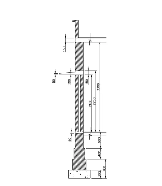
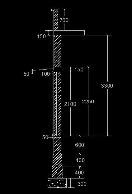
- Create the section of wall footing.
- draw the section in top view.
- Create the rectangle at 600X300mm,again create the rectangle at 350X400mm it will be move with the first rectangle center of above place it.
- Create the rectangle at 300X400mm move with the second rectangle center of above place it.
- Create the rectangle at 230X600mm move with the 3rd rectangle center of above place it.
- explode the rectangle give the offset of 50mm above.
- use the line command draw the corner stright line of 3300mm.both side
- In the middle of the wall create the lintal ,chajja & door opening
- above the wall give the slab thickness as 150mm.
- Create the above parapet wall.
- usse the hatch command.
- Trim the unwanted lines.
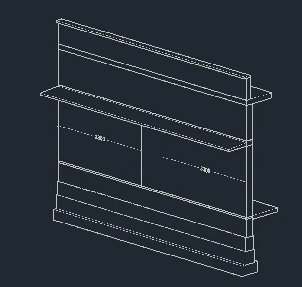
- Use the command "3do" for orbiting the view so that 3d is seen.
- Create the region using region command.
- Rotate the "3drotate" command & use the extrude command extrude with the distance of 7500mm.
- Create the door :Type the UCS command,select the wall face & Type the plan.
- Create the rectangle of @900,2100mm & place the centerof the wall.
- Type the "subtract" select the wall first press enter then select the door press enter.
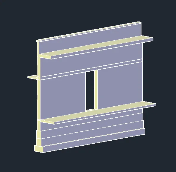
- Click the Visualize & select the Material Browser.
- Assign the materials.
Result