Creating 3D Isometric view of various structural elements in AutoCAD
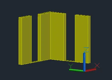
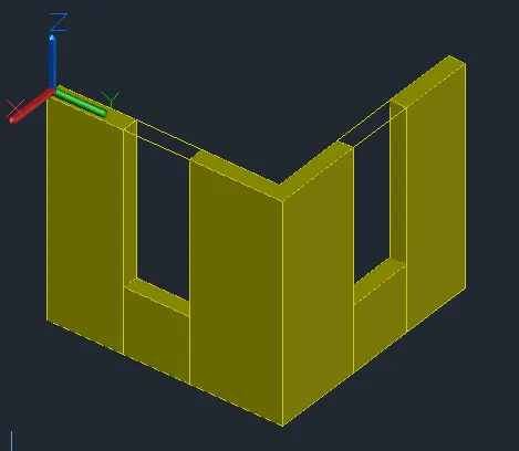
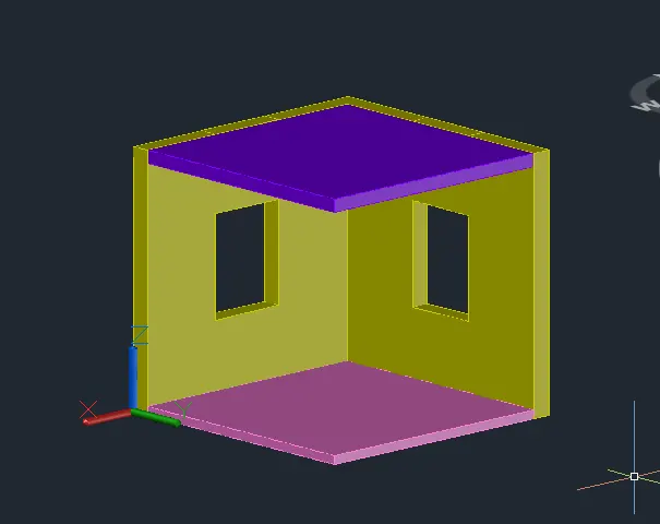
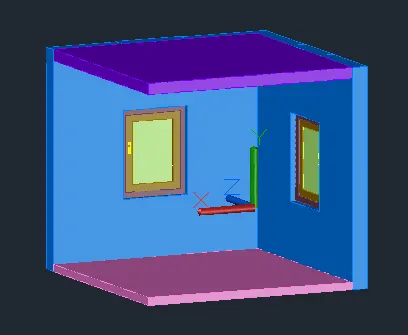
AIM_1: Create a 3D Isometric View of the building with the plan and elevation given.
INTRODUCTION: The main aim of this challenge is to create a 3D isometric view of the building using the plan and elevation given in the question. The procedure for the same is given below.
PROCEDURE:
- Create the plan of the building and convert the same into the region.
- Extrude or presspull the region to the given height in the question.
- Give sill and lintel level by using UCS and rectangle command, and then presspull or extrude it.
- Now Change the UCS and draw the floor and ceiling at the given point and depth as per the question.
- After creating the floor and ceiling using the region and presspull commands, Now start drawing the elevation of the windows.
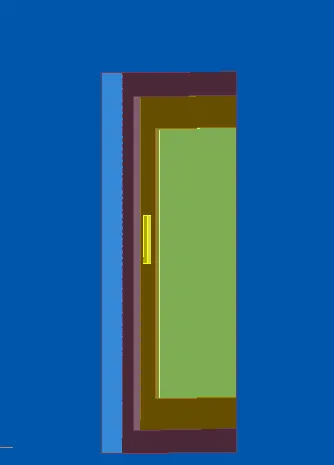
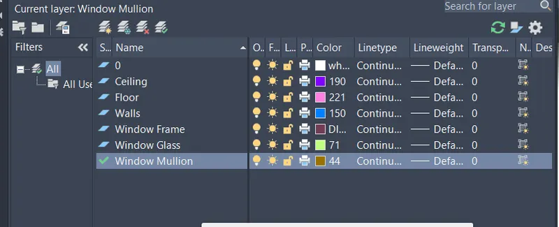
- Create the frame, mullion, and glass and give it a depth effect.
- Thus the isometric view of the building is created.
RESULTS: The commands like presspull, extrude, subtract, region, rectangle, offset, UCS, move and copy were used to create the given geometry. Please look at the below snips for more clarity.
SNIPS:
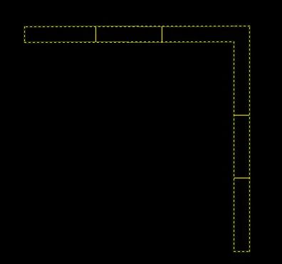
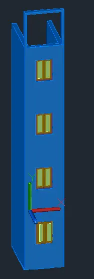
AIM_2: Create the 3D View of the Building Façade as given in the plan and elevation. Also, see the detail of the window.
INTRODUCTION: The main aim of the following question is to draw the 3D elevation of the building facade with windows. The procedure for the same is given below.
PROCEDURE:
- Draw the plan of the building.
- Create the plan into the region.
- Now presspull the whole region to the required height.
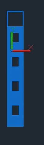
- Take note that the space for the windows is left.
- Once the wall is presspulled, now start with the window.
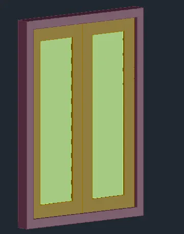
- Create the frame, mullion, and glass and give it a depth effect.
- Thus the isometric view of the building facade is created.
RESULTS: The commands like region, extrude, presspull, UCS, move and copy, offset, layer, etc. were used to create the 3D view of the building facade. Please have a look at the below snips for more clarity.
SNIPS:
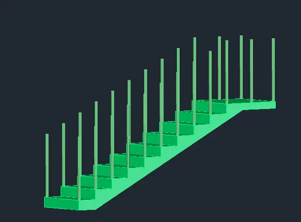
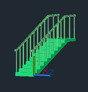
AIM_3: Create the isometric 3d view of a stair with a railing as shown in the plan and elevation. Assume the size of the balustrades and the handrails
INTRODUCTION: In the following question the main aim is to create 3D isometric view of the stairs with railing. The procedure for the same is given below.
PROCEDURE:
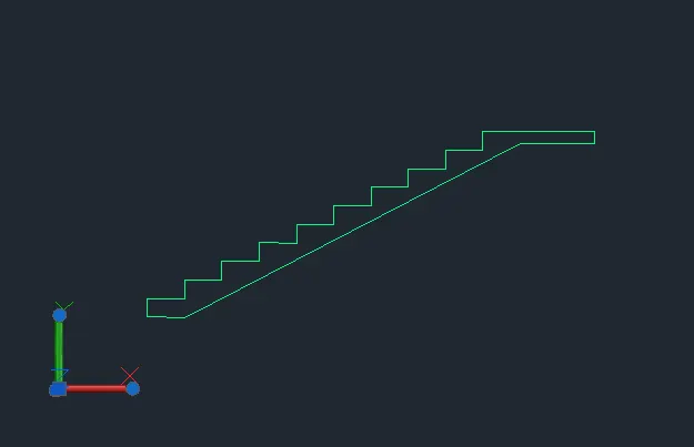
- Draw the side view 2D geometry of the stairs.
- Create the geometry into the region.
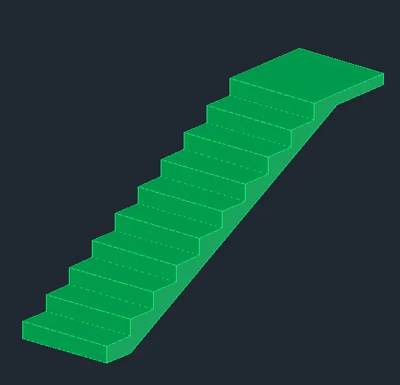
- Presspull or extrude the region to length of 1'.
- Thus the stairs are created.
- Now create a cylinder of 3'2" height on the stair and copy it to all.
- No create a circle above the railing and then transform it to the region.
- Give the path for the railing and then extrude it using the path.
- Thus the staircase with railing is created.
RESULTS: The commands like region, extrude, presspull, UCS, move and copy, offset, layer, cylinder, etc. were used to create the 3D view of the staircase with railings. Please have a look at the below snips for more clarity.
SNIPS:
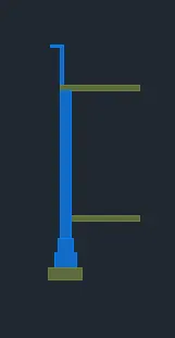
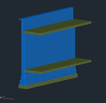
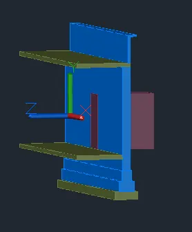
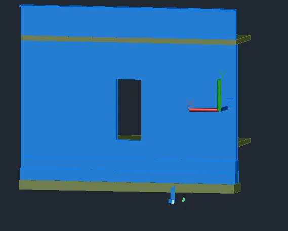
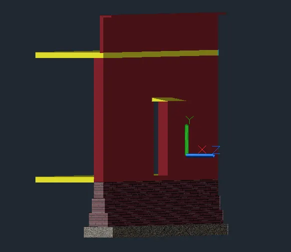
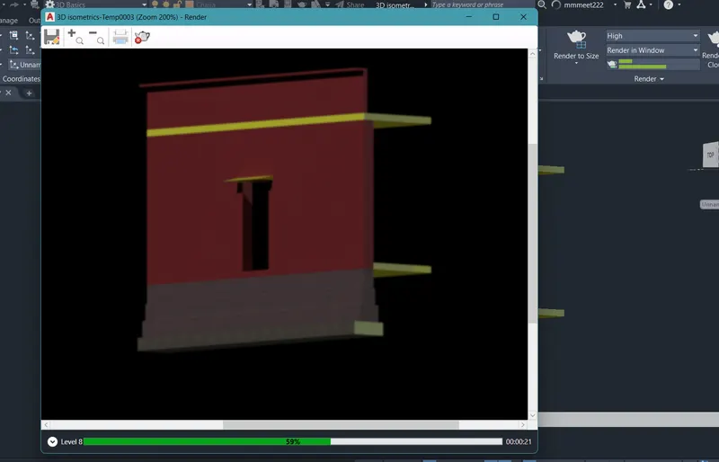
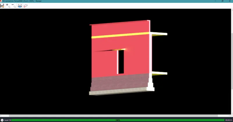
AIM_4: Create the 3D view of a Wall with spread footing. Create the Door opening only. Assume the size of the parapet and the coping. See the plans and elevation for the details. Also, create a rendered view of the model with materials of your choice.
INTRODUCTION: The main aim of this question is to create the 3D view of the load-bearing wall with the foundation and give a rendered view of the same. The procedure for the same is given below.
PROCEDURE:
- Create the geometry of elevation in the XY plane and create it into the region.
- Now extrude the region to the given length as per the question.
- Now create a rectangular box and subtract it from the wall to create an opening for the door.
- Now using the wedge tool create the chajja.
- Once all the components are drawn, start giving materials to it.
- Once the materials are added, create the render of the wall using the RR command.
RESULTS: The commands like region, extrude, presspull, UCS, move and copy, offset, layer, cylinder, materials, render(RR), etc. were used to create the 3D view of the wall with spread footing. Please have a look at the below snips for more clarity.
SNIPS: