Creating 3D Isometric view of various structural elements in AutoCAD
Aim: To create the 3D isometric view of various structural elements in Autocad.
Introduction:
3D Modeling is the process of representation of an any surface of an object in three dimensional. by drawing the 3d model the user can get the more virtual image of their project. In three dimensional drawings we work ith Z axis in addtion to X and Y axis. A 3D objects holds mathematical information that can be used in the engineering analysis as a finite element analysis and computer numerical control. Shading and rendering enhances the visualization of an object. An object is drawn once then can be viewed and plotted from any sngle.
autocad 3D modellings
- Wireframe: Model consist of only points, lines, and curves that describes edges of the object.
- Surface: this defines not only the edges of a 3D objects but also its surface.
- Solid: This is the unambigious and informationally complete representation of the shape of the physical object. the information is more complete in the solid model.
Command used:
- Units command
- UCS Command
- Rectangle command
- offset
- copy
- move
- extrude
- boundary
- region
- mirror
- Dim linear
- dim continuous
- Substract
- union
- Sweep
1. 3D Isometric view of Plan
- Open the new sheet and select the 3d modelling.
- Un enter select the engineering and precision.
- From the view cube select the top plan.
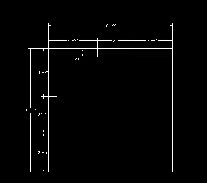
- Draw the rectangle of the size 10'9" x 10'9" and explode the rectangle.
- Offset the top line by 9" downwards and left side line by 9" inside.
- fillet the offset line.
- First line of the window is starting at the 3'6" from the top right side corner.
- Another window on the left wall from the down 3'5" is upward the window is started.
- By using the boundary command the the region is created.
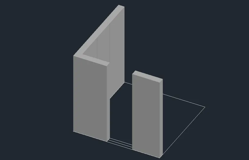
- Extrude the region at a height of 10' and make a union.
- draw the rectangle at the window and move at a 3' distance above.
- make the region of the rectangle and extrude height of 4'
- substract window with the wall.
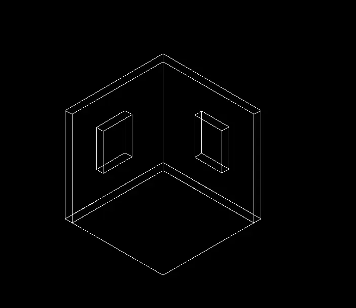
- Draw the rectangle of the size 4' x 4' and offset it by 3" inside and offset the this rectangle by 4" inside.
- Copy this window and placed at the required place.

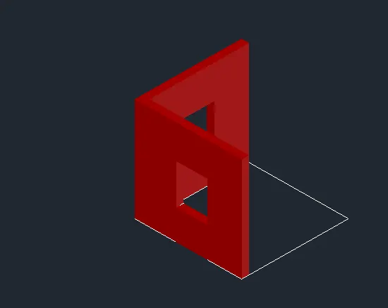
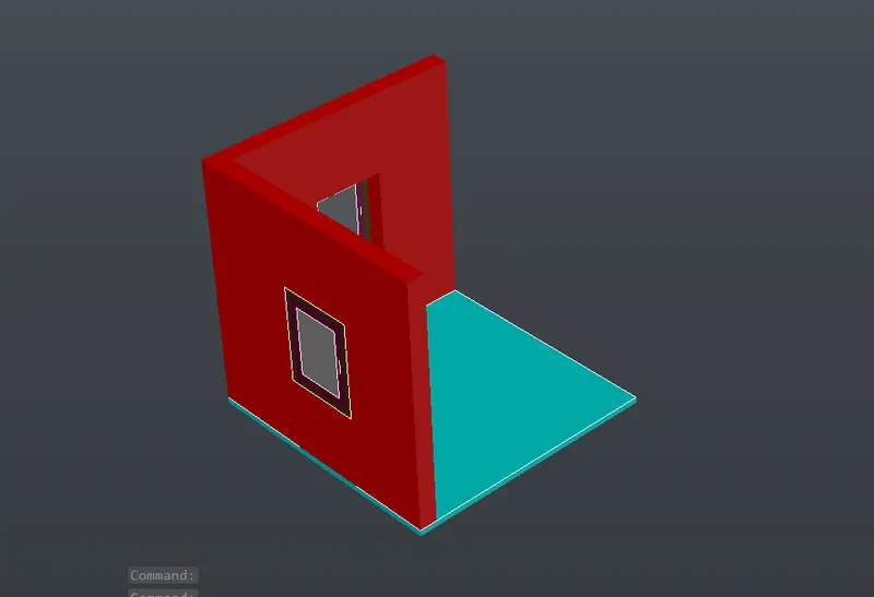
Result:
2. 3d view of building facade
- Open the new sheet and select the 3d modelling.
- Un enter select the engineering and precision.
- From the view cube select the top.
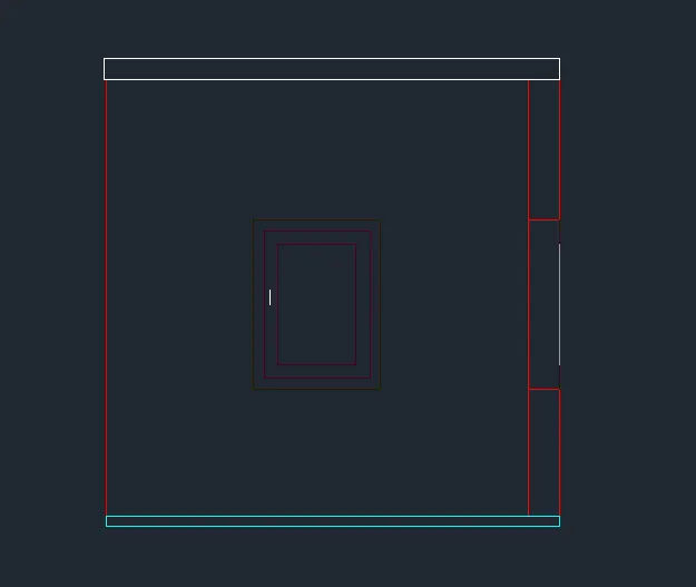
- Draw the rectangle of the size 6'10" x 10'9"
- Explode the rectangle.
- Offsets three sides of the rectangle by a 9" and fillet the lines.
- By using the boundary command the region is created.
- Extrude the solid surface as shown in the figure union it.
- select the wire frame
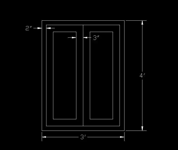
- Draw the rectangle of window size and copy it at 4'6" upwards create the surface and extrude at an height of 4'2"
- move the window upwards at height of 14'7" in z direction and create the surface.
- extrude this rectangle by 4' in z direction.
- Select this window rectangle and it is placed at required position.
- select the substact command first delect the wall next select the area to be deducted. the area of the window is substracted from the wall.
- like this other windows are created.
- Window is drawn as shown in figure and placed it at the required position.
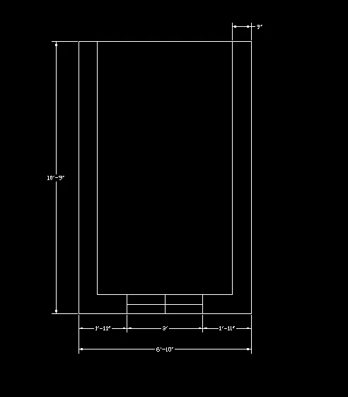
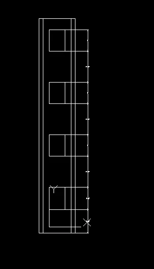
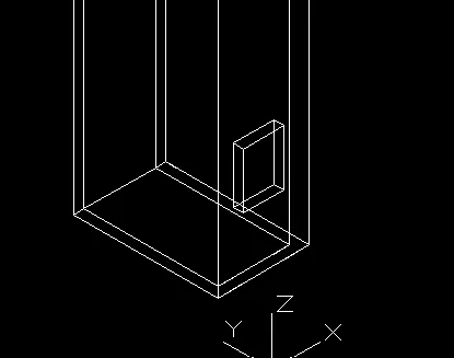
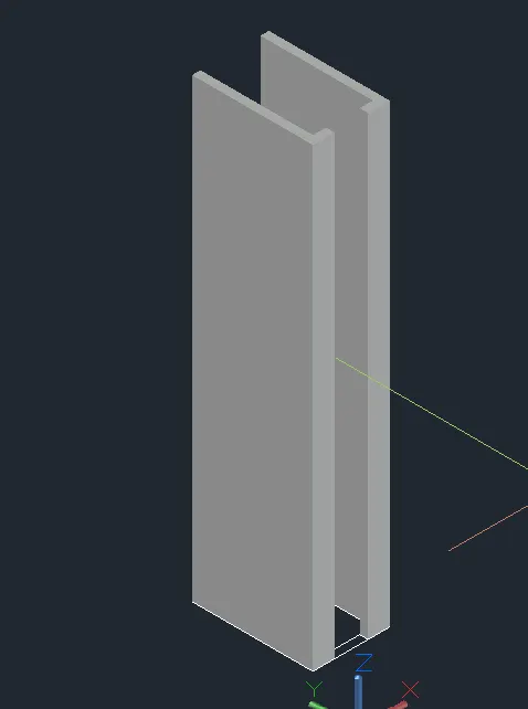
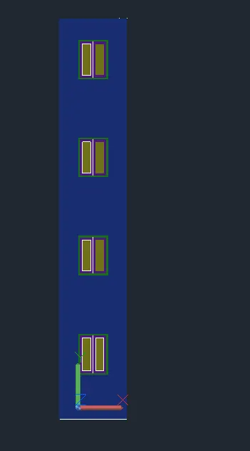
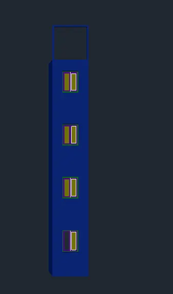
Result:
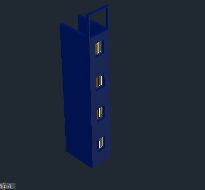
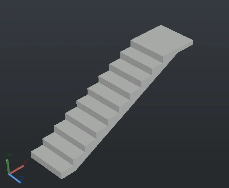
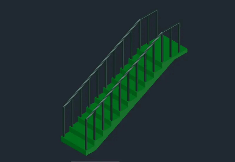
3. Create the isometric 3d view of stair with railing
- Open the new sheet and select the 3d modelling.
- Un enter select the engineering and precision.
- Ucs enter select the x change the y axis direction to vertical.
- Plan enter select the current ucs.
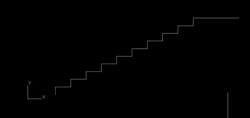
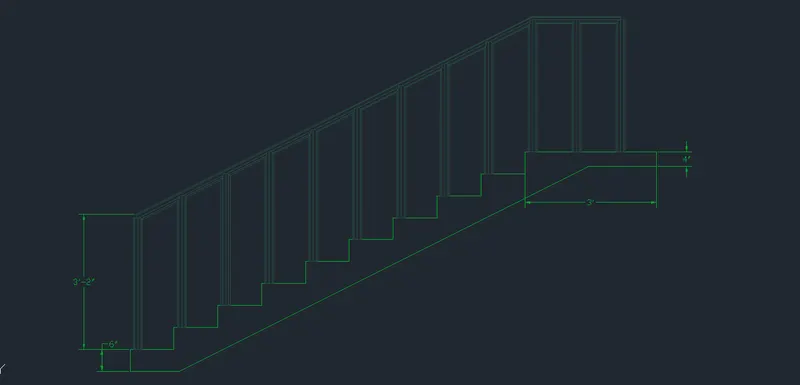
- select the line command draw the line of length 6" vertical and 1' horizontal
- copy the both line placed it at end point of second line.
- 6" waist slab line is drawn.
- By using the boundary option the surface is created and extruded.
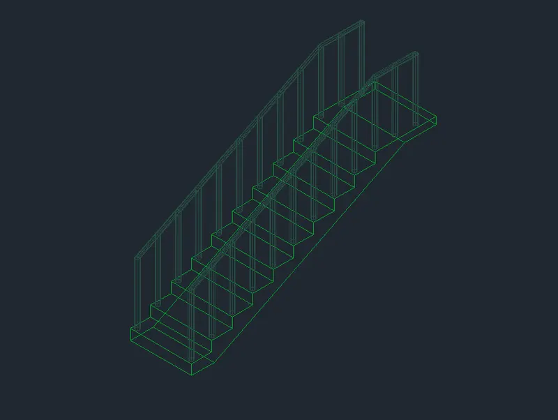
- Draw the line of 3' vertical and circle of 1" diameter and select.
- Select the sweep command and select the object and select the path.
- Move this railing to cornert of the thread and copy the railing and placed itr at every thread.
- By using line command join the top corner of the railing and draw the circle of diameter 2" .
- Select the sweep command and select the circle object and select the path select all lines and union it.
- Copy the railing and placed it on other side.
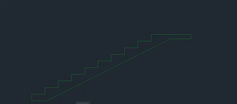
Result:
4. Creation of 3D wall with spread footing
- Open the new sheet select the metric and select the 3d modelling.
- Un enter select the decimal and precision.
- Ucs enter select the x change the y axis direction to vertical.
- Plan enter select the current ucs.
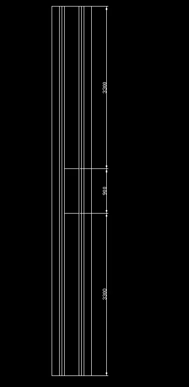
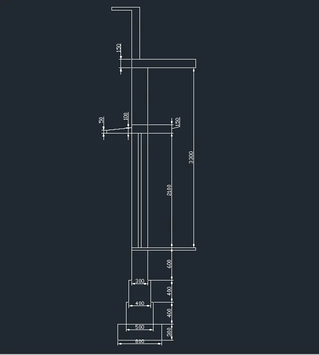
- Draw the rectangle of the size 800 x 300
- Select the line command specify starting point as a 150 mm from the top right corner rectangle.
- next point is 400 mm vertical 50mm horizontal and 400mm vertical and 50 mm horizontal and 550 vertical and 50 mm vertical.
- Except bottom rectangle select the all lines and mirror it.
- join top points by a line and offset it by a 50 mm downward.
- offset top horizotal line by 2100 and 150 mm respectively and join the vertical lines.
- Draw the vertical line of 1050mm and offset it by 300mm left side and draw the slab thickness of 150mm and draw the parapet wall as shown in figure.
- draw the rectangle of door opening at the plith level.
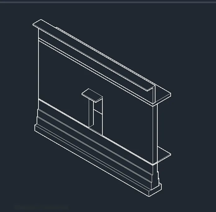
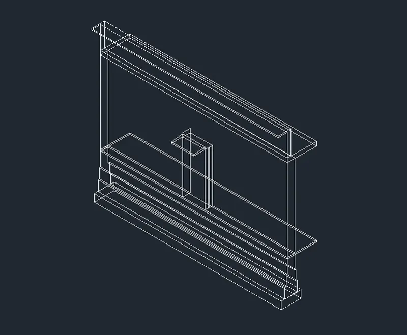
- By using the Boundary command the surafce is created.
- Extrude the surface by 3300 on -ve z direction.
- move the face to 4200 in z direction.
- By using the boundary command surface is created for door opening.
- extrude it in y direction by a distance of 2250.
- By using the substract command the door opening is created.
- The chejja is drawn separately and moved and olaced at the reaquired position.
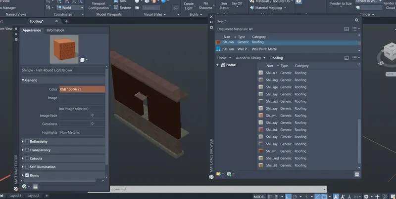
- From the tab select the visualize in the ribbon select the material browser the below dialogue box will appeared.
- For the wall shingle composition brown material is mapped like this for the footing and slab mapping is craeated.
- from the the ribbon selevt the render command and render the object.
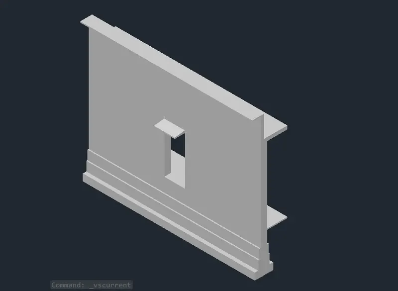
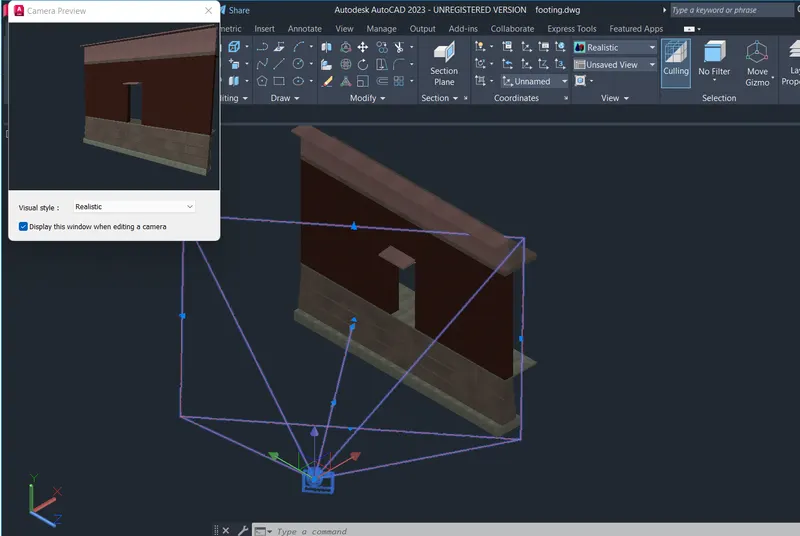
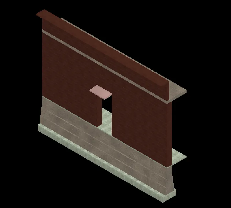
Result: