Creating 3D Isometric view of various structural elements in AutoCAD
Creating 3D Isometric view of various structural elements in AutoCAD
1. Create a 3D Isometric View of the building with plan and elevation given.
AIM:
To create a 3D Isometric View of the building from the given plan and elevation using AutoCAD software and explain the procedure step by step to obtain the result.
INTRODUCTION:
AutoCAD is a computer aided design software and drafting software application.
In this project, i have used important commands and settings like,
* 3D Basics and 3D Modelling setup
* Line, 3Polyline, Polysolid - to create objects, walls.
* Layers - to assign objects and differentiate the drawing.
* Region, Boundary - to create regions.
* Extrude - to extend the object created.
* Subtract - to subtract objects.
* Block - to create window blocks.
* Hide - to hide the extra wireframes and visualize a 3D model.
* UCS - To change the plane and work easily.
* various view types like Hidden, Shade, Isometric etc.. are used.
In the next step, the procedure is explained perfectly.
PROCEDURE:
- Open the AutoCAD software, start from scratch.
- Choose Imperial system.
- Select 3D MODELLING space from the settings and start drawing.
- Set the units to Engineering and Limits to 0,0 to 1000',1000'.
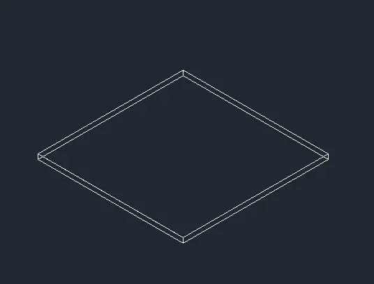
- Using Rectangle command, draw an square of 10'9".
- And extrude it to a distance of 4".
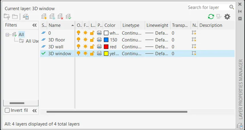
- Create Different layers and colors for differentiating objects like 3d floor, 3d wall and 3d window.
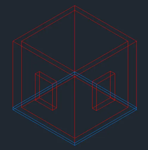
- Using POLYSOLID command, set the height as 10' ,width as 9" and start drawing and finish the wall on the floor.
- Using Rectangle command, create a window structure of 3'x4' and 3'2"x4' and place it on the wall.
- Using Extrude command, extend the window to 9" as like the thickness of the wall.
- Now, using SUBTRACT command, subtract the windows from the wall.
- Again Using rectangle command, cover the ceiling and Extrude it to a thickness of 6".
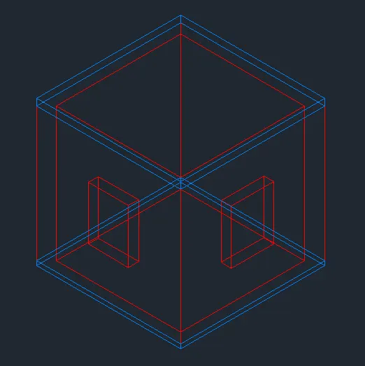
- Shaded view of the drawing for better visualisation.
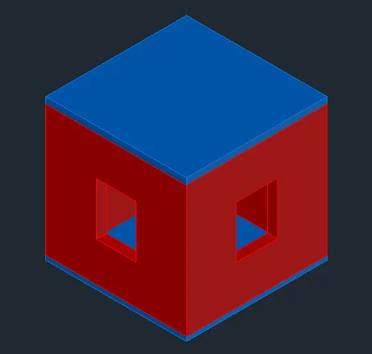
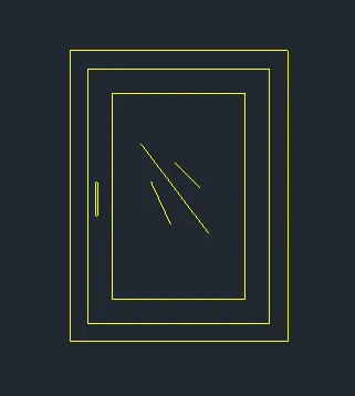
- Create a window elevation and make it into a BLOCK and place it in window space created in the wall.
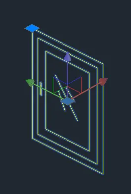
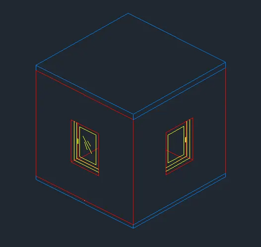
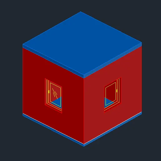
- The following image shows the completed 3D view of the building.
- Completed 3D SHADED view of the building.
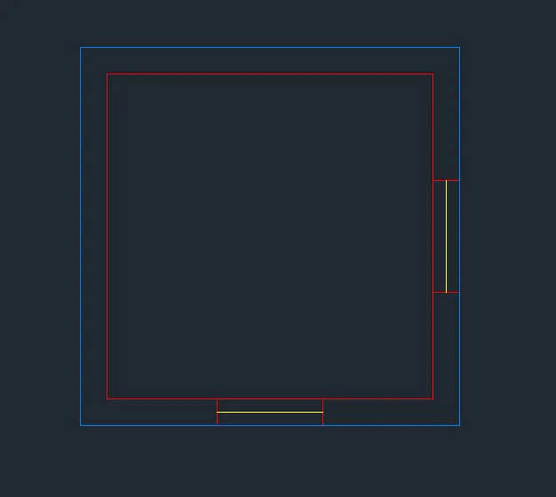
- It is the top view/ Plan of the 3D Building.
RESULT:
2. Create the 3D View of the Building Façade as given in the plan and elevation. Also, see the detail of the window.
AIM:
To create a 3D View of the Building Facade from the given plan and elevation using AutoCAD software and explain the procedure step by step to obtain the result.
INTRODUCTION:
AutoCAD is a computer aided design software and drafting software application.
In this project, i have used important commands and settings like,
* 3D Basics and 3D Modelling setup
* Line, 3Polyline, Polysolid - to create objects, walls.
* Layers - to assign objects and differentiate the drawing.
* Region, Boundary - to create regions.
* Extrude - to extend the object created.
* Subtract - to subtract objects.
* Block - to create window blocks.
* Hide - to hide the extra wireframes and visualize a 3D model.
* UCS - To change the plane and work easily.
* various view types like Hidden, Shade, Isometric etc.. are used.
In the next step, the procedure is explained perfectly.
PROCEDURE:
- Open the AutoCAD software, start from scratch.
- Choose Imperial system.
- Select 3D MODELLING space from the settings and start drawing.
- Set the units to Engineering and Limits to 0,0 to 1000',1000'.
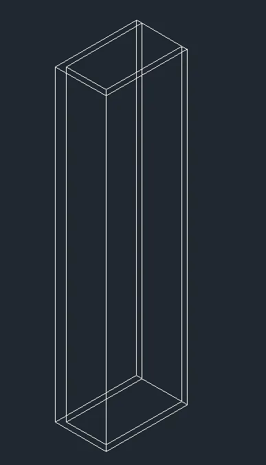
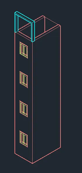
- Using POLYSOLID command, give the input for height as 40'10" and width as 9" and create the wall having dimensions 10'9"x6'9".
- The following image shows the top view of the wall.

- This is the wall created using POLYSOLID command as mentioned before.
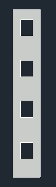
- Using rectangle command, draw a rectangle at the base with 3' length and 9" wall thickness as breadth.
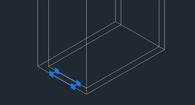
- Using UCS command, make the front face as WORKING PLANE.
- Now, using COPY command, copy the rectangle from the base and place it at regular intervals as mentioned in the given drawing to create the window spaces.
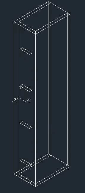
- Using EXTRUDE command, select all the window rectangles and extend it commanly to a height of 4'.
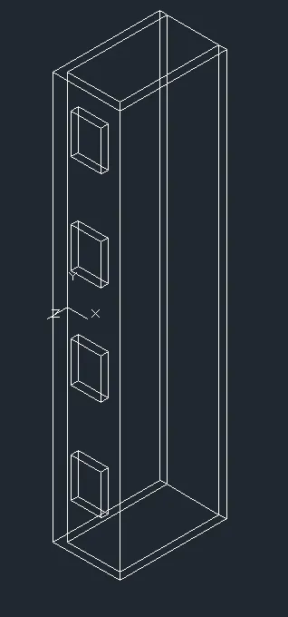
- Change the UCS to world and subtract the window spaces from the walls using SUBTRACT command.
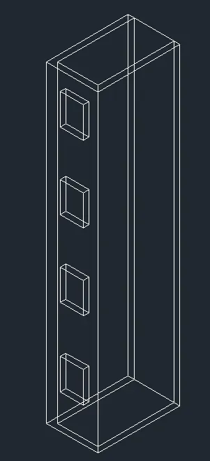
- The following image shows the wall after subtracting the window spaces.
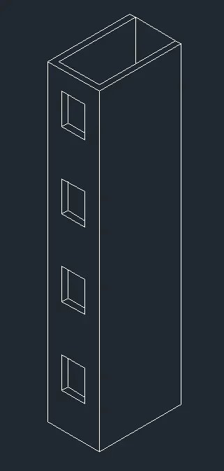
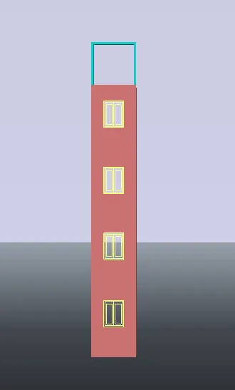
- Front shaded view of the building wall.
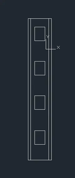
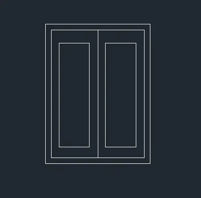
- Using the commands Rectangle and Line, the window is created and converted into a block.
- The window is then copied/inserted in the window spaces created before.
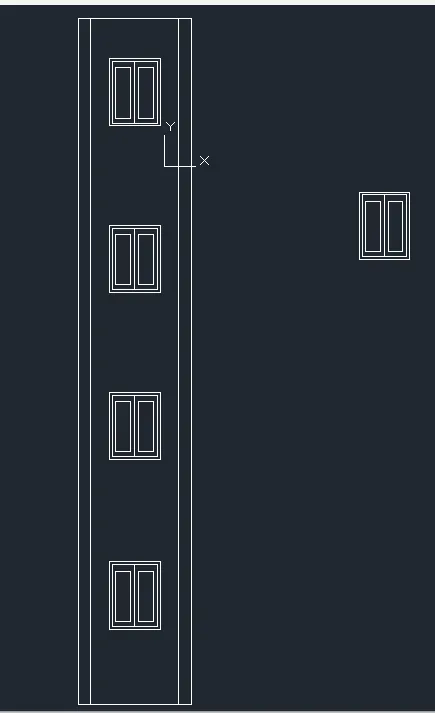
- The wall and windows are assigned different layers and colors.
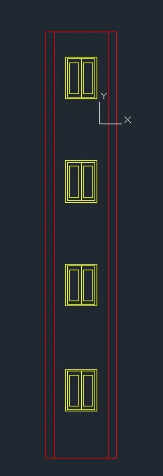
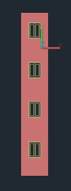
- SHADED view of the 3D wall created.
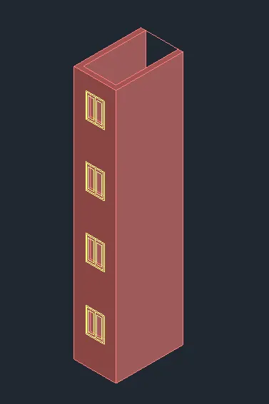
- Using UCS command, change the plane as required and start working.
- Using Polysolid, the top facade is created of height 9" and width 4" in the respective plane.
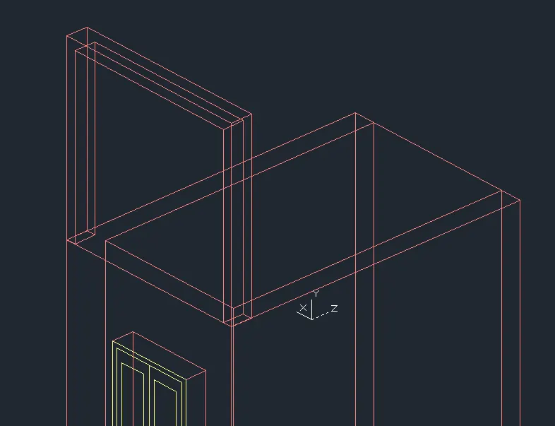
- The color of the top facade is changed for better visualisation.
RESULT:
3. Create the ismoteric 3d view of a stair with railing as shown in the plan and elevation. Assume the size of the balustrades and the hand rails.
AIM:
To create the ismoteric 3D view of a stair with railing from the given plan and elevation using AutoCAD software and explain the procedure step by step to obtain the result.
INTRODUCTION:
AutoCAD is a computer aided design software and drafting software application.
In this project, i have used important commands and settings like,
* 3D Basics and 3D Modelling setup
* Line, 3Polyline, Polysolid - to create objects, walls.
* Region, Boundary - to create regions.
* Extrude - to extend the object created.
* SWEEP - to create the hand railing.
* Hide - to hide the extra wireframes and visualize a 3D model.
* UCS - To change the plane and work easily.
* various view types like Hidden, Shade, Isometric etc.. are used.
In the next step, the procedure is explained perfectly.
PROCEDURE:
- Open the AutoCAD software, start from scratch.
- Choose Imperial system.
- Select 3D MODELLING space from the settings and start drawing.
- Set the units to Engineering and Limits to 0,0 to 1000',1000'.
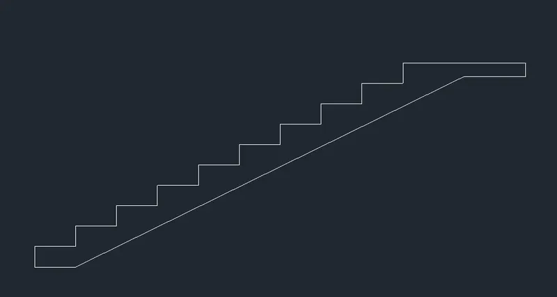
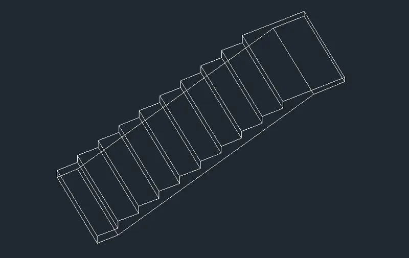
- Using the command 3P (3D polyline), draw the stairs with rise 6", tread 1' and landing of 3'.
- Using EXTRUDE command, extend the stairs to a width of 4'.
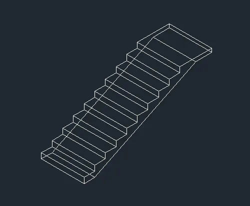
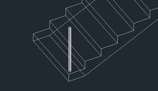
- To create hand railing, Create a circle on the step and Extrude it to height of 3'.
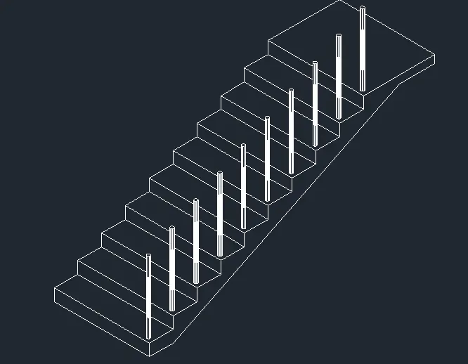
- Copy the vertical bars created on each steps as shown in figure.
- Using 3D polyline (3P) and SWEEP command, the hand railing is created along the path.
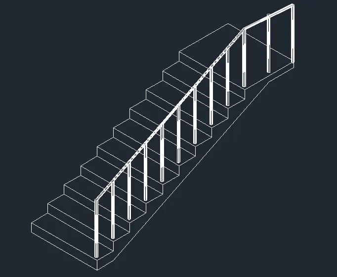
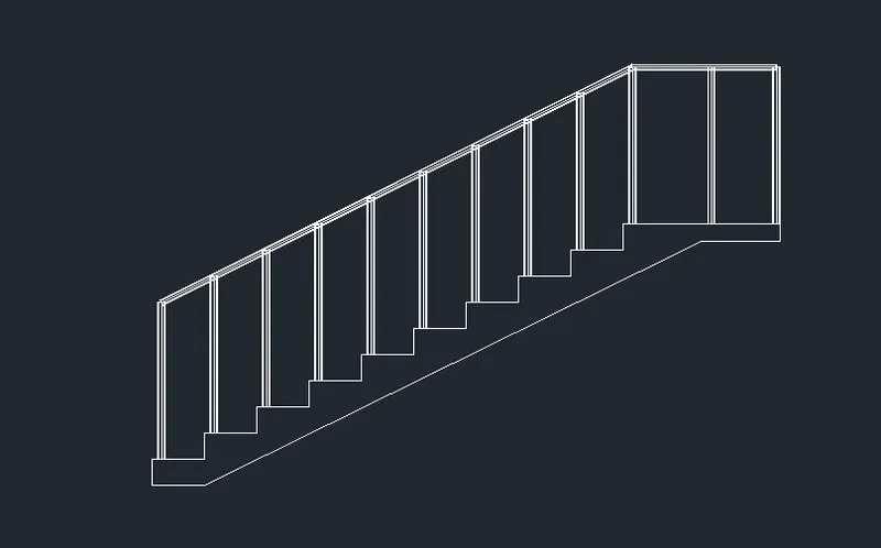
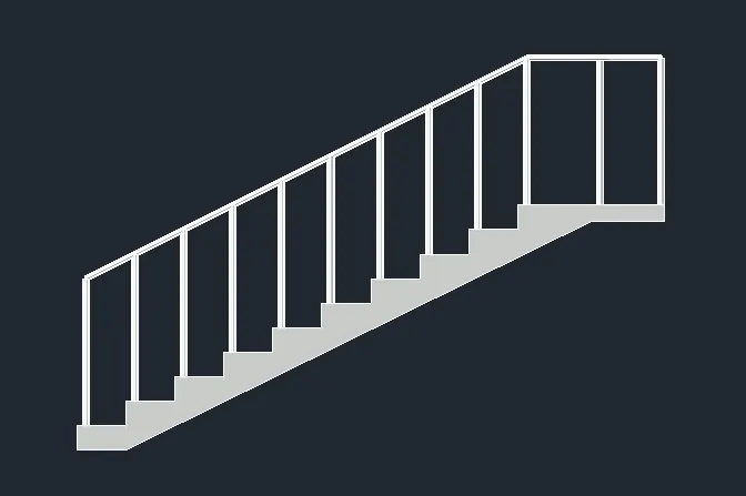
- Front view of the staircase.
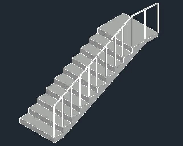
- SHADED view of the completed staircase.
RESULT:
4. Create the 3D view of a Wall with spread footing . Create the Door opening only. Assume the size of the parpaet and the coping. See the plans and elevation for the details. Also, create a rendered view of the model with materials as of your choice.
AIM:
To Create the 3D view of a Wall with spread footing from the given plan and section using AutoCAD software and explain the procedure step by step to obtain the result.
INTRODUCTION:
AutoCAD is a computer aided design software and drafting software application.
In this project, i have used important commands and settings like,
* 3D Basics and 3D Modelling setup
* Line, 3Polyline, Polysolid - to create objects, walls.
* Layers - to assign objects and differentiate the drawing.
* Region, Boundary - to create regions.
* Extrude - to extend the object created.
* Subtract - to subtract objects.
* Hide - to hide the extra wireframes and visualize a 3D model.
* UCS - To change the plane and work easily.
* various view types like Hidden, Shade, Isometric etc.. are used.
In the next step, the procedure is explained perfectly.
PROCEDURE:
- Open the AutoCAD software, start from scratch.
- Choose Metric system.
- Select 3D MODELLING space from the settings and start drawing.
- Set the units to Decimal and Limits to 0,0 to 100000,100000.
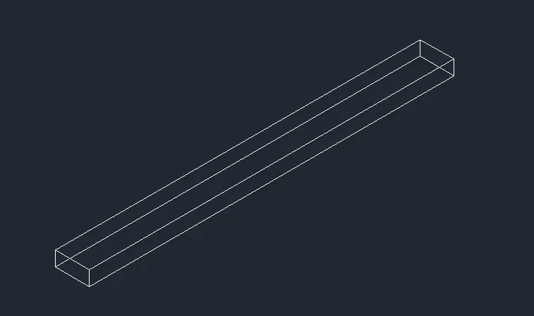
- Using Rectangle command, draw a rectangle of 7500x800 and Extrude it to a height of 300mm.
- Using UCS command, change the UCS as desired(front face) and start drawing the wall structure using 3P command.
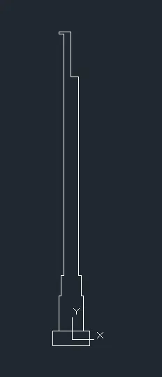
- Using EXTRUDE command, extend the wall created to 7500mm.
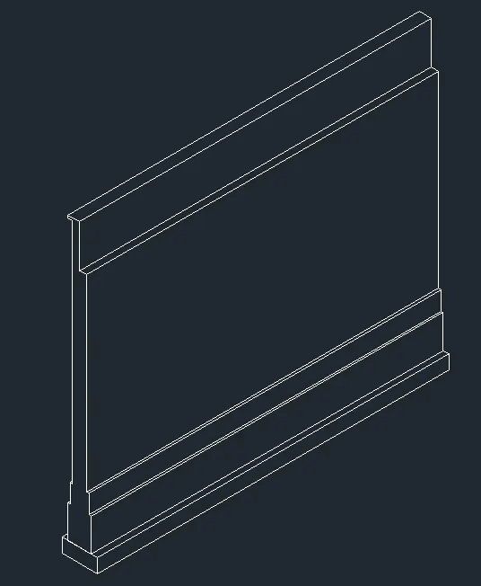
- Now, Using Rectangle and Extrude command, create a door spacing 900x2100 in the middle of the wall.
- Using Subtract command, subtract the door solid to create the door opening.
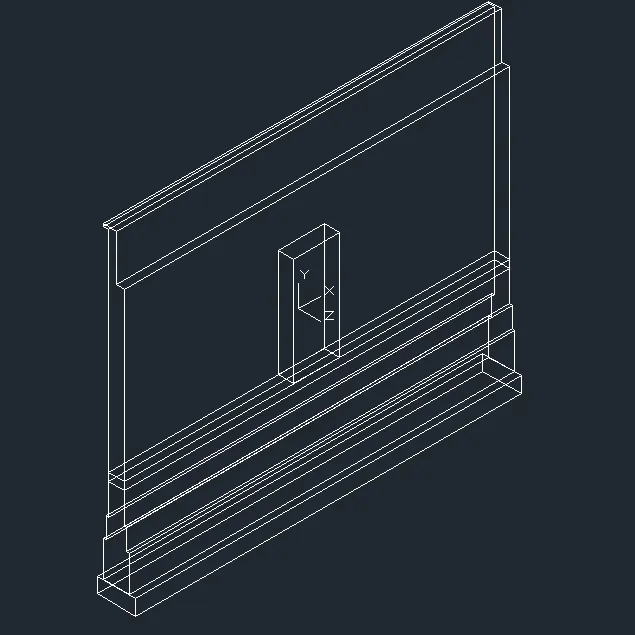
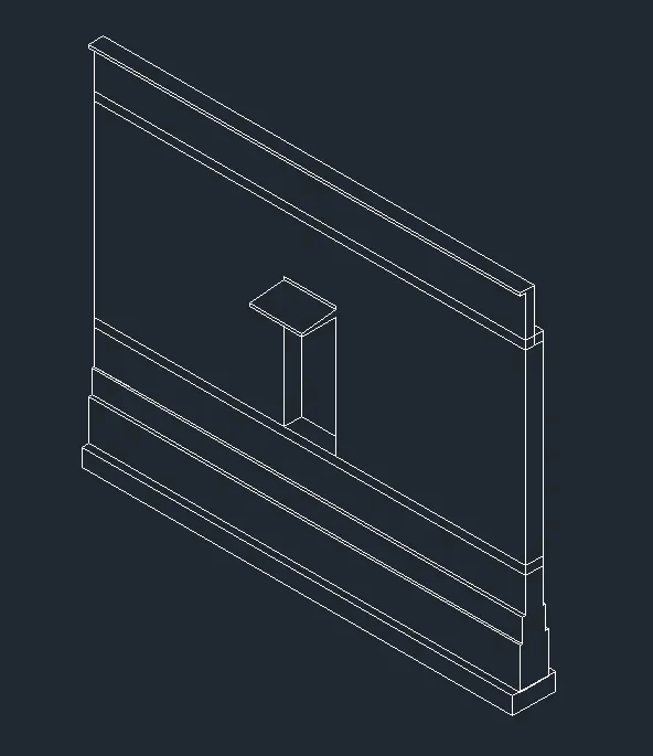
- After SUBTRACT command is used as mentioned before and HIDE view.
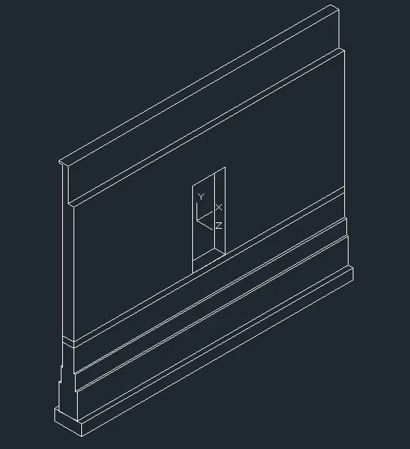
- 3D Isometric Front view of the wall.
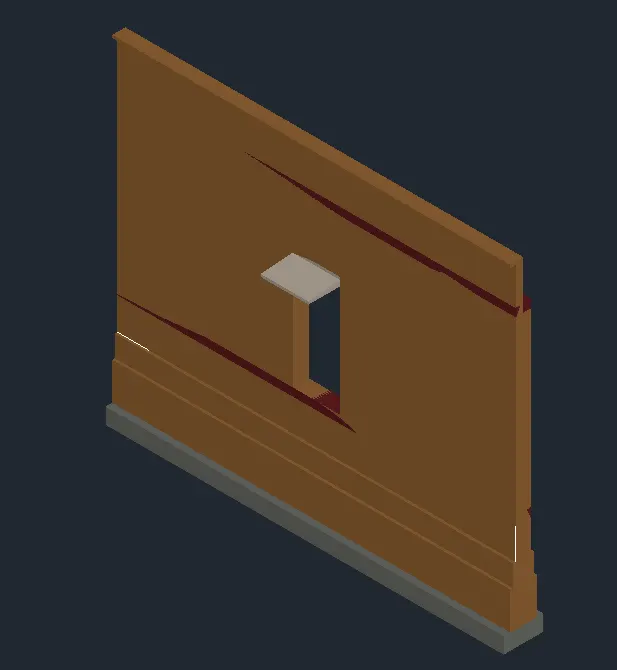
- Now, Using MATERIAL BROWSER, material properties are assigned for walls and concrete.
- Like for WALLS - Wall Painting is given and for Concrete Footing, Floor and Slab - Concrete Property is given.
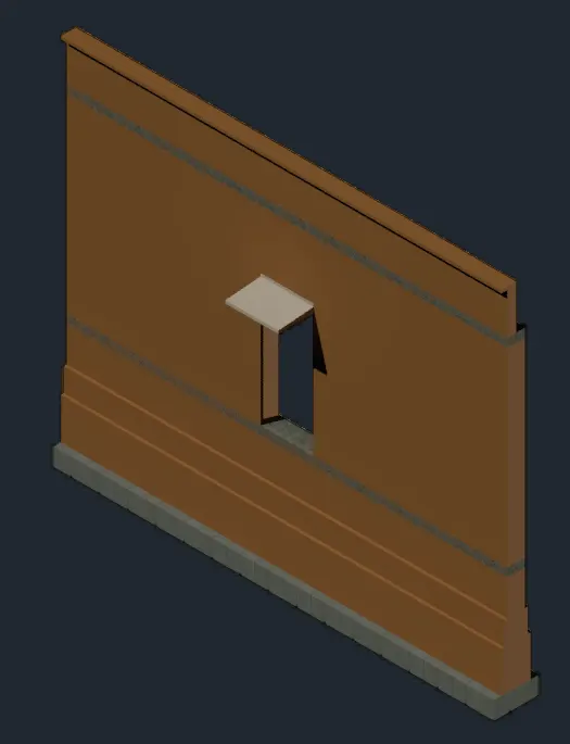
- Using RR command, rendering of 5 Levels is done.
- Input RR command, Select the region and start rendering.
- The following image shows the rendered image of the 3D footing wall with door opening.
RESULT: