Creating 3D Isometric view of various structural elements in AutoCAD
Q1. Create a 3D Isometric View of the building with plan and elevation given.
Aim: To draw a section of a building plan for a room
Step:1) Open the 3D modeling interface in autocad
Step:2) Draw the outline of wall plan and elevation in 2D
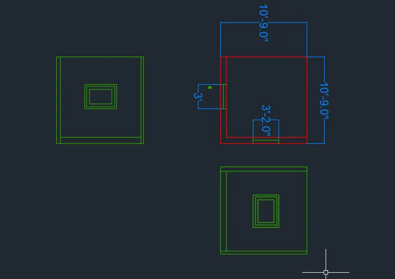
Step:2) Create boundary/region and extrude the walls
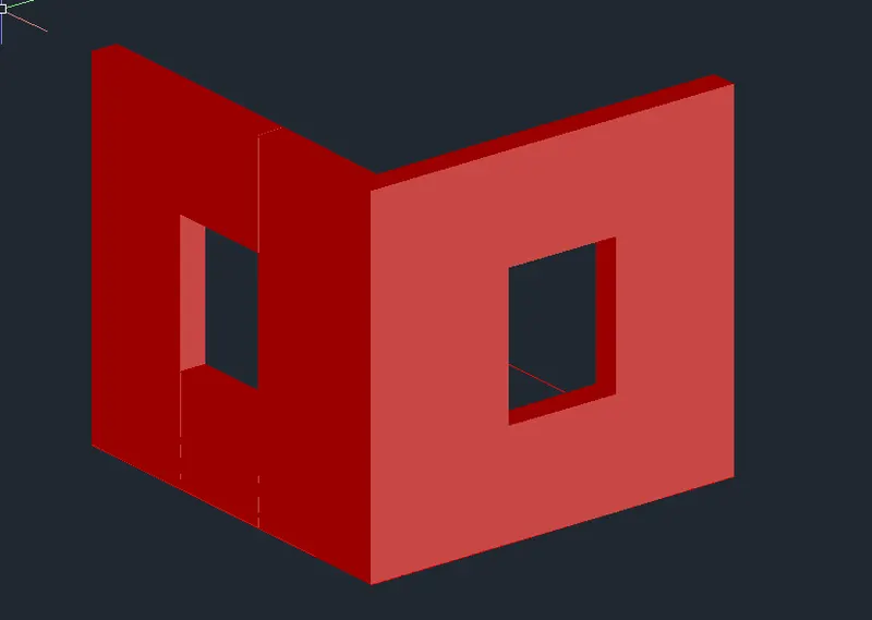
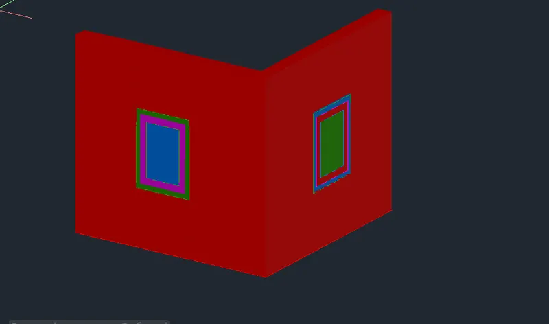
Step:3) Extrude and subtract the window
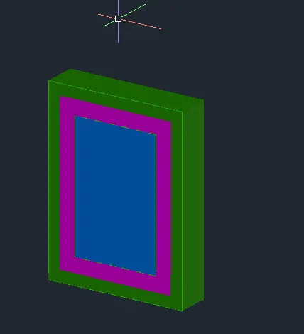
Result: The wall is created
Q2. Create the 3D View of the Building Façade as given in the plan and elevation. Also, see the detail of the window.
Aim: to create a building elevation
Step:1)Create the plan for the facade
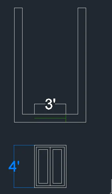
Step:2) extrude the wall and copy paste to top levels, create the window
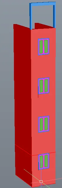
Result: the elevation is created
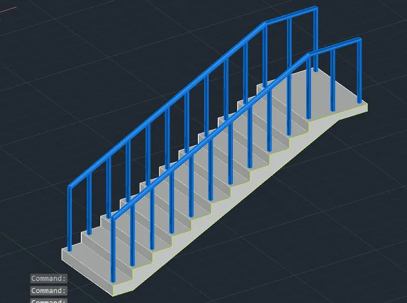
Q3. Create the ismoteric 3d view of a stair with railing as shown in the plan and elevation. Assume the size of the balustrades and the hand rails.
Aim: To create stair in 3D
Step:1) Drawvthe stair flight in plan view and create boundary/region
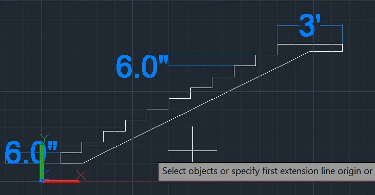
Step:2) extrude the stair to width
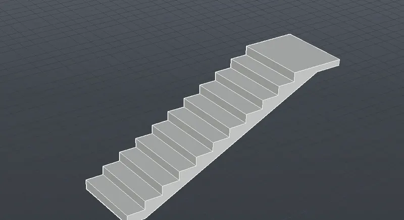
Step:3) Create the ballusters by ucs on stair landing and extruding a circle
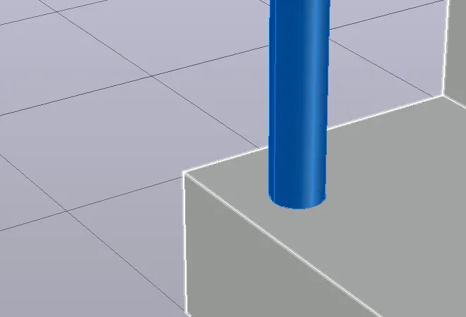
Step:4) Create the handrail by sweep command
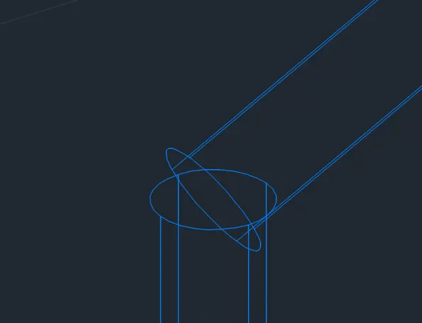
Result:) Place the rail on stair
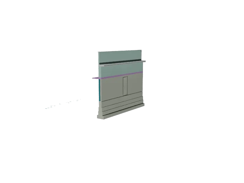
Q4. Create the 3D view of a Wall with spread footing . Create the Door opening only. Assume the size of the parpaet and the coping. See the plans and elevation for the details. Also, create a rendered view of the model with materials as of your choice.
Aim: To create a wall and spread footing
Step :1) Create the plan and elevation in 2D
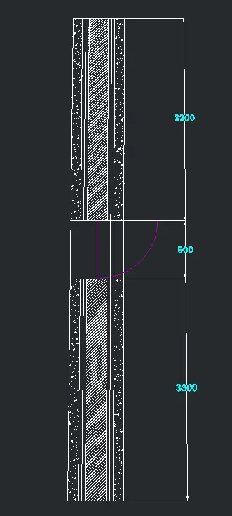
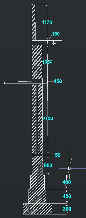
Step :2) Develop the 3D model from elevation
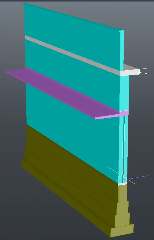
Step :3) Place the door on the wall
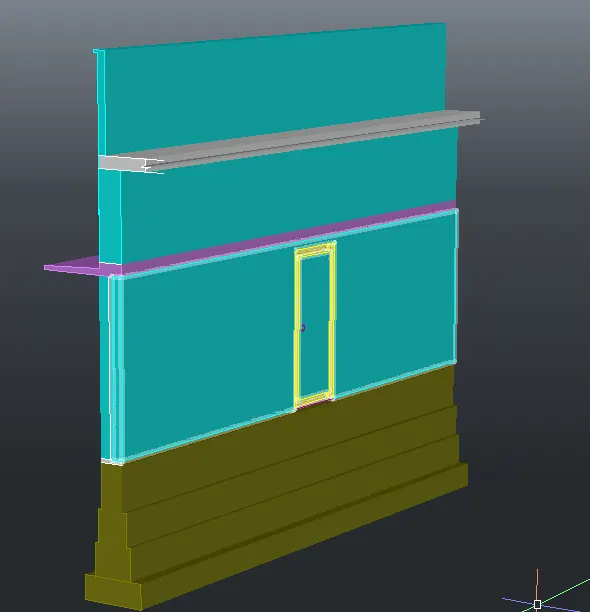
Result:) Rendered view