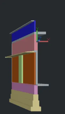
Creating 3D Isometric view of various structural elements in AutoCAD
Ans 1. Create a 3D Isometric View of the building with plan and elevation given.
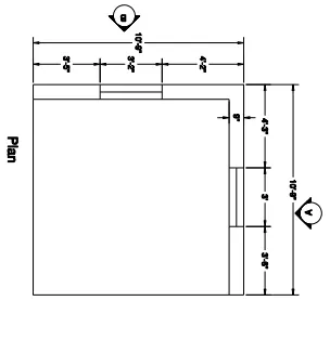
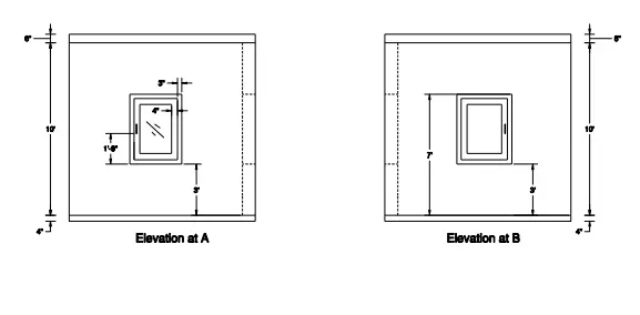
Aim :- Create a 3D Isometric View of the building with plan and elevation as shown in the Figure in AutoCAD.
Introduction :- Create a 3D Isometric View of the building with plan and elevation as shown in the Figure in AutoCAD.
Procedure :-
- Draw top view plan
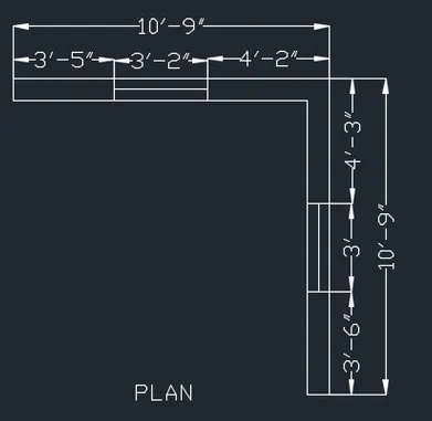
- With line command draw line of 10'9" verticallay and horizontally in such a way that it form L-shape wall
- Offset of 9" is given to the two lines
- Give an offset of 4'2" from the corner of the wall
- Again give an offset of 3'2" from the line for the window
- Draw window
- Similarly, on the other wall side give an offset of 4'3" from the corner of the window
- Use command DO for orbiting the view so that 3D view is seen
- Now, create a region in the wall area by BO command for the boundary
- Now, extrude the region and give a height of ' using extrude command
- Now, create opening for windows and draw a rectangle over the window portion and extrude it to sill level
- Similarly, create a rectangle at the top and extrude it downwards to the height of ' from the top
- Union the wall using union command
- Similarly, crate the wall on the other side
- crate layer for walls nd place it layer
- In the top view by polyline , craete outerline of the plan
- Then place it in bottom by move command
- Create the region by boundary and extrude it downwards to the height of 4"
- Now, again create the elevation in 2d and draw ELEVATION-A from plan in top view
- Project the wall lines from plan and also window lines
- Give the height as 10' and then offset lines 3' from bottom and top to create window
- Then offset 3" for the frame and 4" for the mullion
- Also offset 4' downwards for plinth and 6' upwards for the roof slab
- Craete different layers for frame, mullion and glass
- Plac ethe 2D drawing in alignment to 3D
- Group the elevation by group command so that all will be in selected together at once
- By using 3d rotate commmand rotate the image making it parallel to the 3D wall
- Place second elevation in 3rd object by snapping the corner and move it to the side parallel to the 3D wall face
- craeting fromae, mullion and glass of window by boundary commmand and the create a region fo rthe frame
- extrude the region by giving -3" value
- Similarly,
- crate the region for mullions by BO command and extrude it by 0.6"
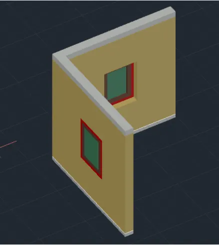
- Move the 3D wndow to the opening of window to crate 3D model
- Similarly, crate the elevation B by going to the top view and extending the lines from the plan and rest process is same.
Result :-
Top View
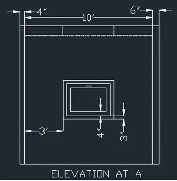
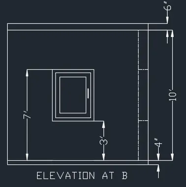
Front View
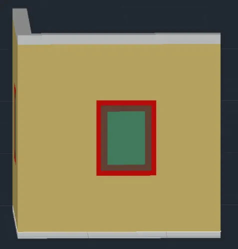
Isometric View
Ans 2. Create the 3D View of the Building Façade as given in the plan and elevation. Also, see the detail of the window.
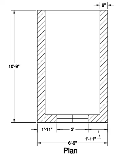
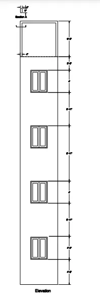
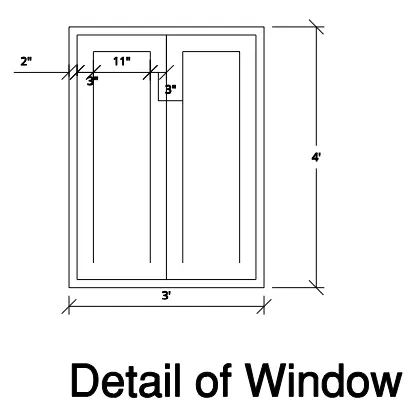
Aim :- Create the 3D View of the Building Façade as given in the plan and elevation. Also, see the detail of the window details in AutoCAD.
Introduction :- Create the 3D View of the Building Façade as given in the plan and elevation. Also, see the detail of the window details in AutoCAD .
Procedure :-
- Create the plan with rec of 10'9" and 6'9" and fofset of 9" for the wall thickness is given and create the window of 3' width
- With extrude command create the region by giving height of 10'11"
- Create window by creating the rectangle at the bottom of winndwo position
- Extrude it to a height of 4'6" and similarly create a rectangle at the top and extrude 2'5" downwards
- With union command make all walls in union
- Crtae the elevation of plan in 2D top view
- As window is in the side of plan, side elevation is taken by projecting from the lines from the plan
- Window detainling is done
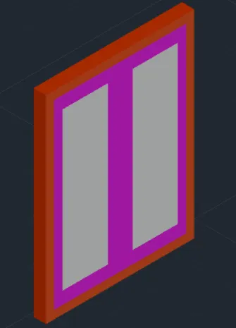
- Offset of 2" for the frame is given and 3" for mullions then 12" will be the glass area
- Create the window in 3D
- Group the elevation and place the elevation in front of the 3D image
- With 3D rotate commnad rotate the elevation to 270 degrees
- Place in parallel to face and move aside
- Ungroup and delete the walls and keep only windows
- Create a region in the frame by window by 'BO' command and making frame as layer
- Extrude 3" for thickness of frame
- For mullions, create another region in different layer and extrude -1.2"
- For glass region creation excrude -0.6
- Move the object and place the window in gap in 3D wall
- Now, create the floor and go to top view and create a extrude it by 5"
- Now create the second floor and group the cretaed model and copy the created first floor on top
- Copy the floors one above the others
- Again, create the top frame and type UCS command and place ucs on the top of building
- Draw rectangle of 9'X4' and extrude it by 6'5"
- Copy it on the other side
- Again create the rectangle on the top face and extrude it by -4"
- Create the roof on the top by rectangle and extrude it
Result :-
Top View
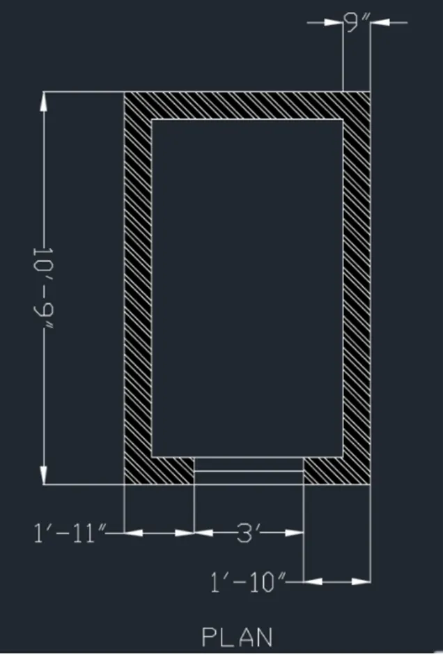
Isometric View
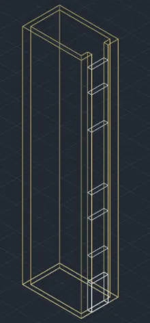
Isometric View
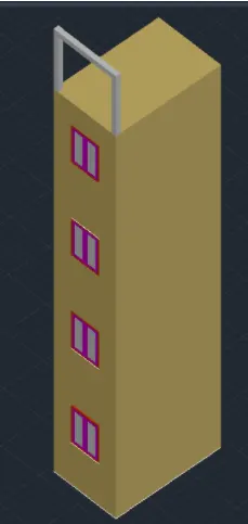
Isometric View
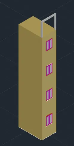
Isometric View
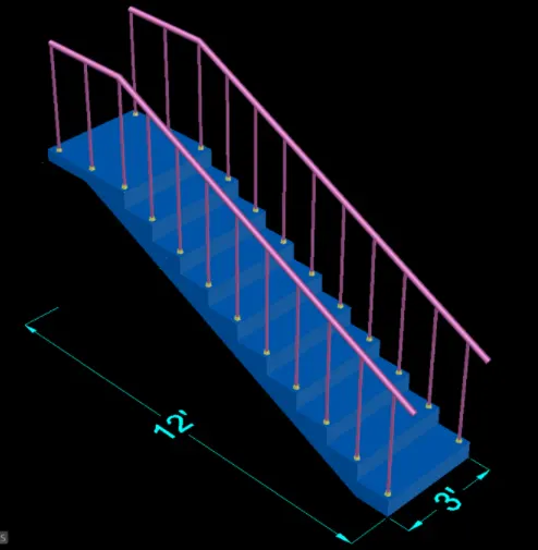
Ans 3. Create the ismoteric 3d view of a stair with railing as shown in the plan and elevation. Assume the size of the balustrades and the hand rails.
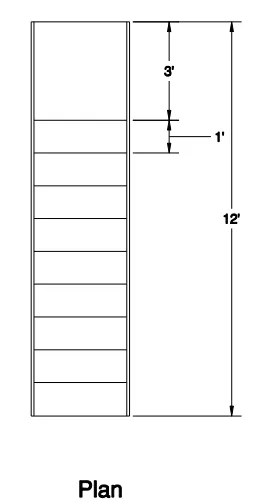
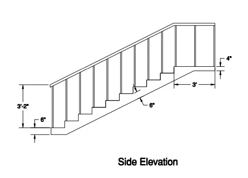
Aim :- Create the ismoteric 3d view of a stair with railing as shown in the plan and elevation. Assume the size of the balustrades and the hand rails in AutoCAD.
Introduction :- Create the ismoteric 3d view of a stair with railing as shown in the plan and elevation. Assume the size of the balustrades and the hand rails in AutoCAD.
Procedure :-
- Create the thread (T) and riser (R) as 6' and draw the steps in the top view 2D wireframe
- Landing is 3' and waist slab is of 6" thickness
- Join all the section of stairs
- Create a region by boundary command
- With 3d orbit place the section in such a way that it is visible
- Extrude 3' towrds the side as3' is taken as width of stairs
- With 3d rotate select X-axis and give value 90 degrees
- Now create the balusters and handrails by placing the UCS on the thread and cretae cricle of 2" dia and height as 3'2"
- Copy it in all th threds and also in the landing
- For handrails cretae a polyline joining the balustreades by 3D polyline
- Cretae a circle of radius 2" and seep it by selcting the circle and then the polyline
Result :-
Top View
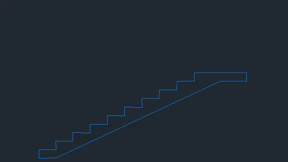
Isometric View
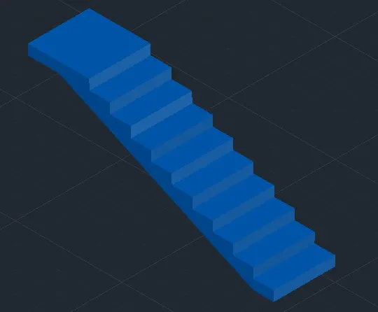
Isometric View
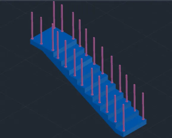
Final Isometric View
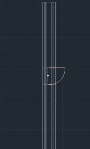
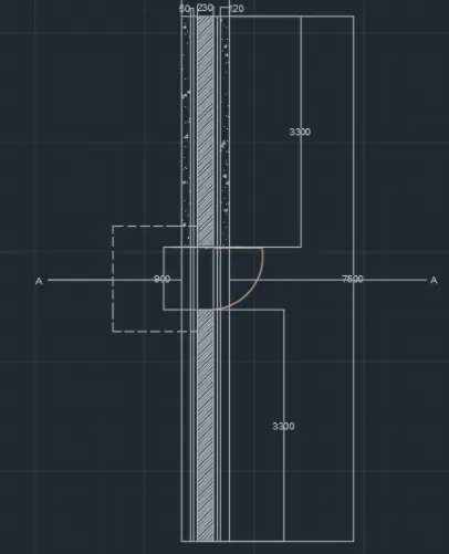
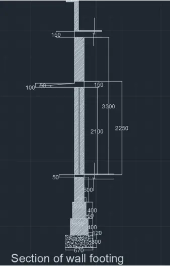
Ans 4. Create the 3D view of a Wall with spread footing . Create the Door opening only. Assume the size of the parpaet and the coping. See the plans and elevation for the details. Also, create a rendered view of the model with materials as of your choice.
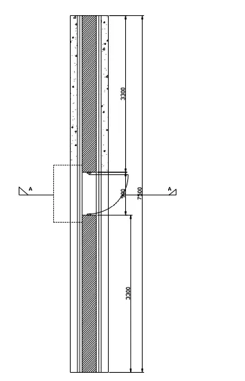
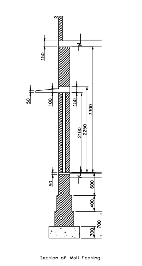
Aim :- Create the 3D view of a Wall with spread footing . Create the Door opening only. Assume the size of the parpaet and the coping. See the plans and elevation for the details. Also, create a rendered view of the model with materials as of your choice in AutoCAD.
Introduction :- Create the 3D view of a Wall with spread footing . Create the Door opening only. Assume the size of the parpaet and the coping. See the plans and elevation for the details. Also, create a rendered view of the model with materials as of your choice in AutoCAD.
Procedure :-
- Open AutoCAD
- In the right left corner click on the setting icons that is the icon of workspace
- Select 3D modelling
- Enter UN (units ) command in the command box and change its type aas engineering and select precision as 0'-0"
- Now enter dim style in command box and change the type as engineering and select primary units as engineering and give precision as 0'-0"
- Select line command and draw in top view or in 2D mode
- Draw the figure as given question into AutoCAD
- Command boundary to create different boundaries
- Command region to cretae the region for extruding
- Extrude the plan to the designed heights to draw the wall footing
- Open layer properties and assign layers to different components
Result :-
Top View
Isometric View