Creating 3D Isometric view of various structural elements in AutoCAD
1)
Aim:- To create the given 3D figure by using Auto CAD software.
Procedure:-
a) I changed the modelling into 3Dmodelling and then i created this diagram.
b) By using polar and also rectangular co-ordinte systems (By cylindrical and spherical) i created this figure.
c) By following given dimensions i created this diagram.
d) finally i created this diagram as below.
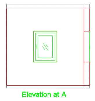
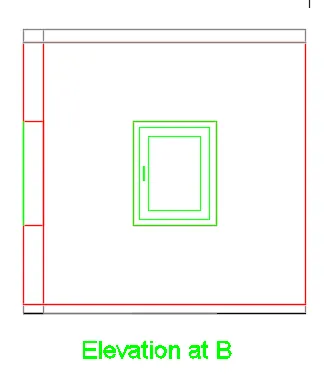
Result:- FInally i created this diagram by using AutoCAdD3D.
2)
Aim:- To create the given 3D figure by using Auto CAD software.
Procedure:-
a) I changed the modelling into 3Dmodelling and then i created this diagram.
b) By using polar and also rectangular co-ordinte systems (By cylindrical and spherical) i created this figure.
c) By following given dimensions i created this diagram.
d) finally i created this diagram as below.
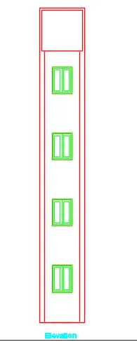
Result:- FInally i created this diagram by using AutoCAdD3D.
3)
Aim:- To create the given 3D figure by using Auto CAD software.
Procedure:-
a) I changed the modelling into 3Dmodelling and then i created this diagram.
b) By using polar and also rectangular co-ordinte systems (By cylindrical and spherical) i created this figure.
c) By following given dimensions i created this diagram.
d) finally i created this diagram as below.
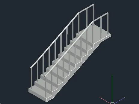
Result:- FInally i created this diagram by using AutoCAdD3D.
4)
Aim:- To create the given 3D figure by using Auto CAD software.
Procedure:-
a) I changed the modelling into 3Dmodelling and then i created this diagram.
b) By using polar and also rectangular co-ordinte systems (By cylindrical and spherical) i created this figure.
c) By following given dimensions i created this diagram.
d) finally i created this diagram as below.
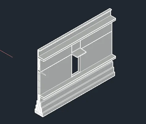
Result:- FInally i created this diagram by using AutoCAdD3D.