Conjugate Heat Transfer Analysis on a graphics card.
Aim:
Perform a steady-state conjugate heat transfer analysis on a model of a graphics card.
- Run the simulation by varying the velocity from 1m/sec to 5m/sec for at least 3 velocities and discuss the results.
- Find out the maximum temperature and heat transfer coefficient attained by the processor.
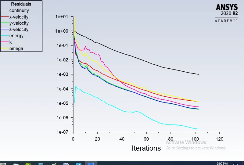
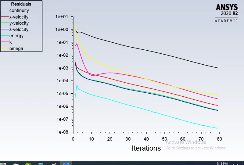
- Prove that the simulation has achieved convergence with appropriate images and plots.
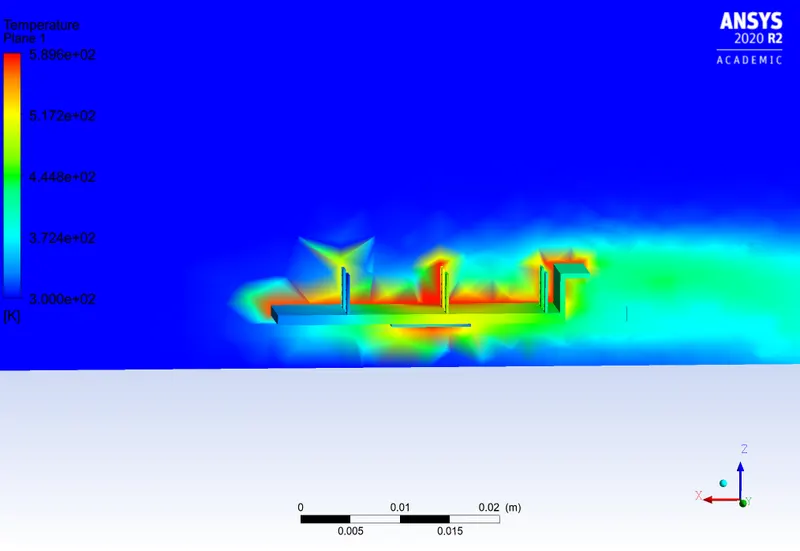
- Identify potential hotspots on the model.
Conjugate Heat Transfer (CHT)
1.The Conjugate Heat Transfer (CHT) analysis allows for the simulation of heat transfer between solid and fluid domains by exchanging thermal energy at the interfaces between them.
2. The CHT approach therefore has benefits for those applications where heat transfer is either non-uniform or difficult to calculate empirically
3.conduction through solids, free and forced convection in the gases/fluids and thermal radiation.
4. Examples of CHT are conduction through solids, free and forced convection in the gases/fluids and thermal radiation.simulation of heat exchangers, cooling of electronic equipment, and general-purpose cooling and heating systems.
5.The CHT approach has an advantage overFE thermal analysis in that wall heat transfer coefficients and their local variations on surfaces are directly calculated within the model rather than based on simplified empirical calculation
Graphics card:
1.The Graphics Card is responsible for rendering an image to your monitor, it does this by converting data into a signal your monitor can understand.The better your graphics card the better, and smoother an image can be produced. This is naturally very important for gamers and video editors.
2.Integrated – Graphics built into the motherboard where no add-in card is used. You’ll find these built into most ‘standard’ laptops and computers, they are a cost-effective model but cannot be easily upgraded.
3.For users branching out into gaming or video editing, a discrete graphics card is usually needed to speed up the image processing time. Without this, the user may find their game lagging or jittering at crucial points.
Geometry:
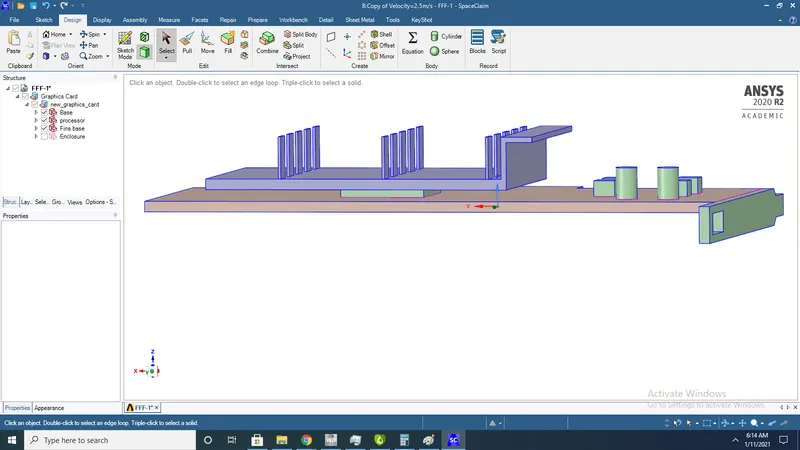
1. Graphics card
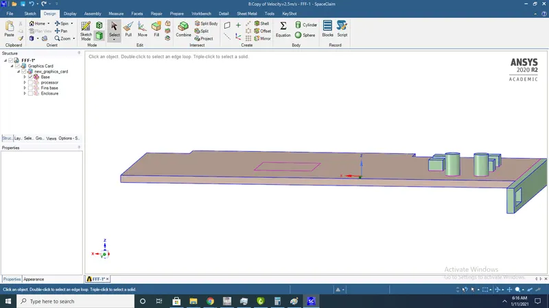
2.Base (fr-4)
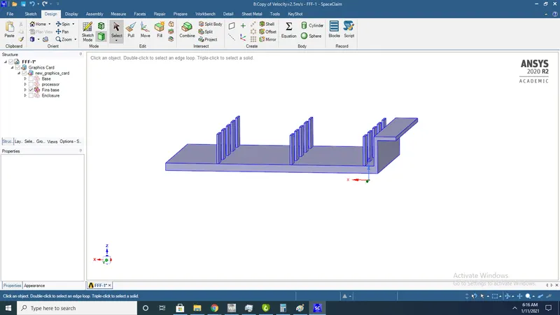
3.Fin base (Aluminium)
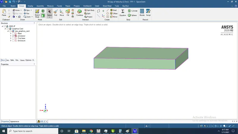
4.Processor (Steel)
Meshing:
Baseline mesh:
Named selecion:
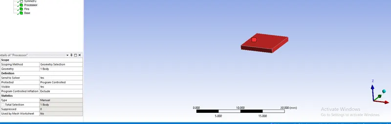
1.Processor
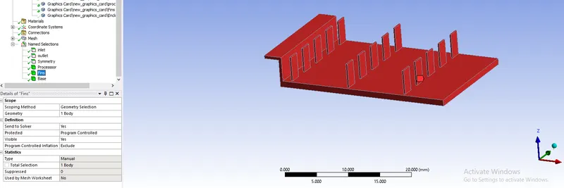
2.Fins
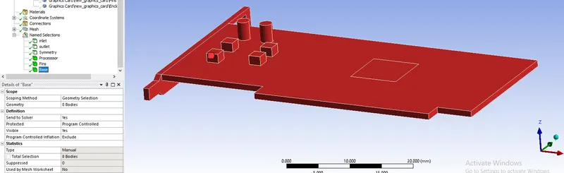
3.Base
Baseline mesh:
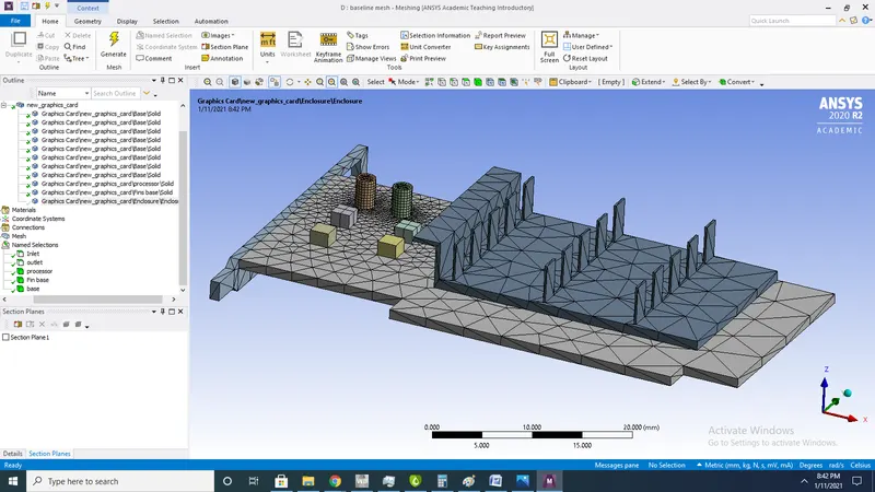
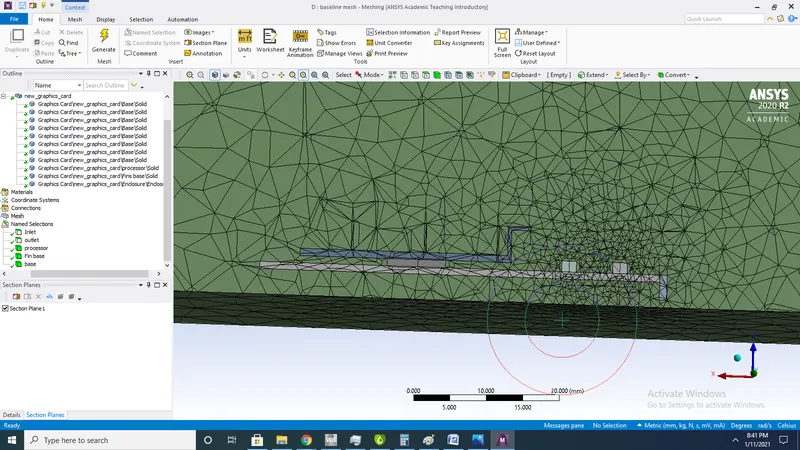
2.Section plane
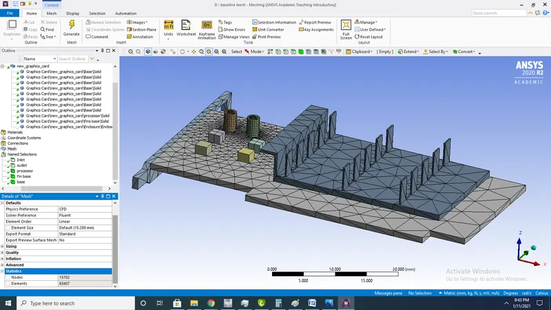
3.stastics
No of elements in base line mesh 83407
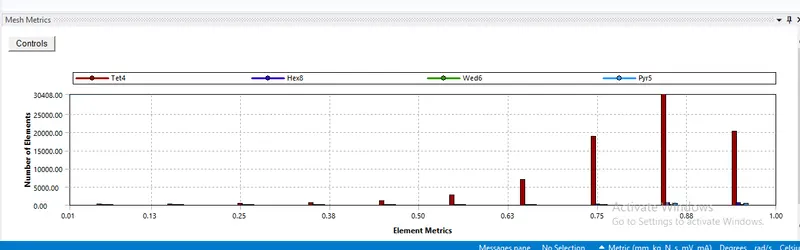
4.Quality
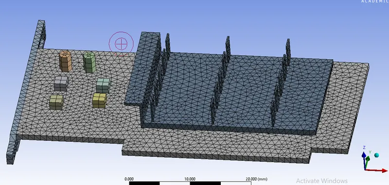
Refined mesh:
1.
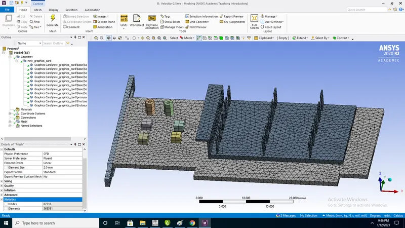
2.sectional view
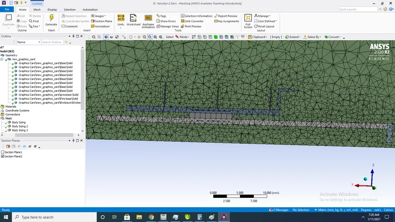
stastics:
No of elements after refining =365591
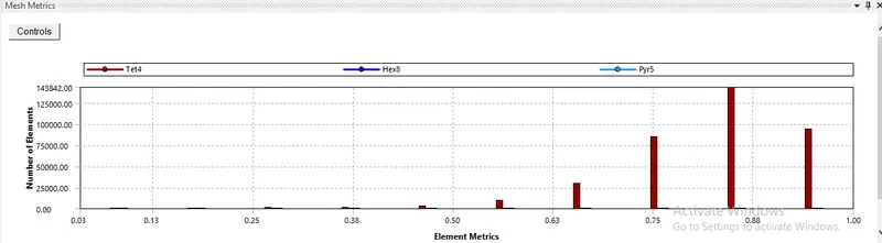
Quality:
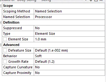
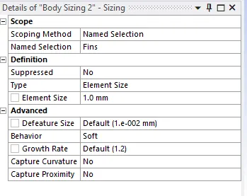
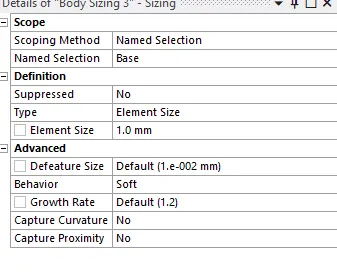
Body sizing:
Fin base body sizing:
Base:
Setup:
Setup:
1)General
Type: Pressure-based
Time: steady
Velocity formulation: Absolute
2D Space : Planar
2)Models:
Viscous: Turbulent :K-omega
K-omega model:
K-omega model is used for problems which having physics near the wall .so hear heat generation takes place in processor which is nearer to wall
3)Materials:
Fluid= Air
Solid= Aluminium,Steel,FR-4
| S.no | Parts | Materials | Density | Specific heat | Thermal conductivity |
| 1 | Base | Rf-4 | 1900 | 1150 | 0.29 |
| 2 | Processor | Steel | 8030 | 502.48 | 16.27 |
| 3 | Fins | Aluminium | 2719 | 871 | 202.4 |
4)Boundary conditions:
Inlet:
Velocity=1,2.5,5m/s
Temperature=300K
Processor:
Heat generation=10W(Assumed)
Volume of processor=(64mm^3) (Taken from space cliam)
5)Cell zone conditions: Processor-solid-source-one energy-156250000W/m^3
Intialization:
Hybrid intialization
Results:
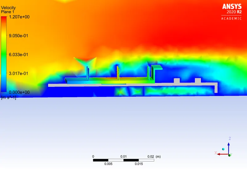
Base line mesh (Velocity=1m/s):
Residuals:
Temperature contour:
Velocity contour:
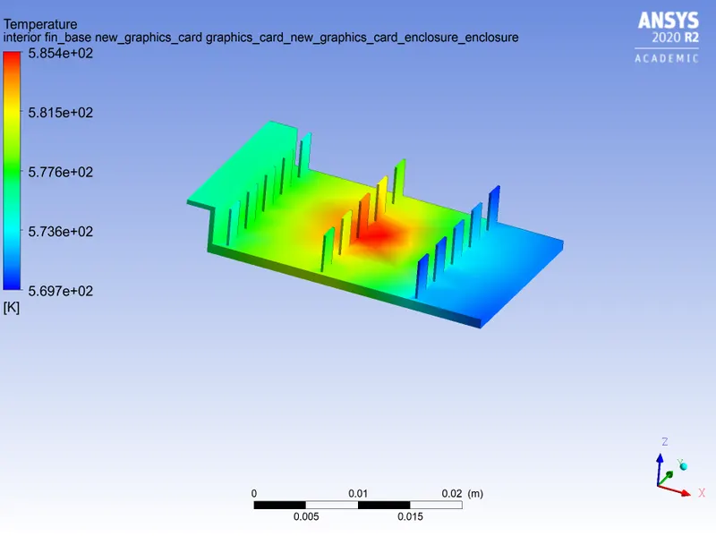
Temperature of fins base:
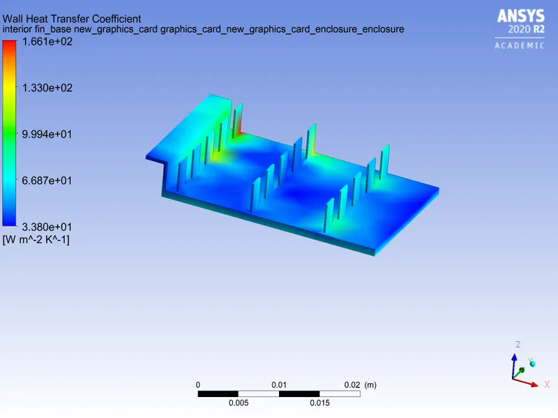
Wall heat transfer coefficentof fins :
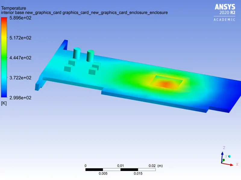
Temperature of base:
Wall heat transfer coefficient of base:
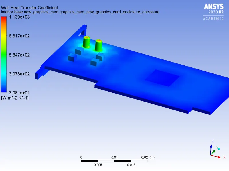
Cutplane Wht:
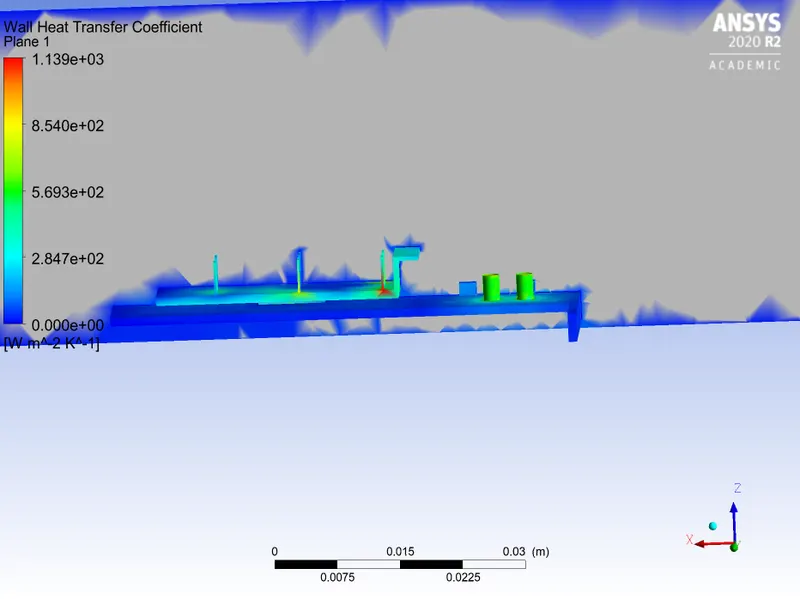
case(2):
Velocityat 1m/s with refined mesh:
Residuals
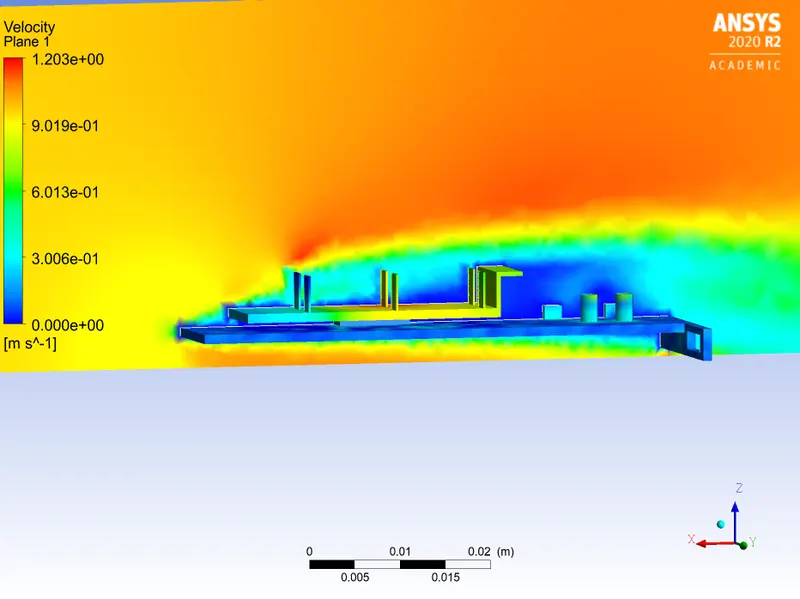
Velocity contour:
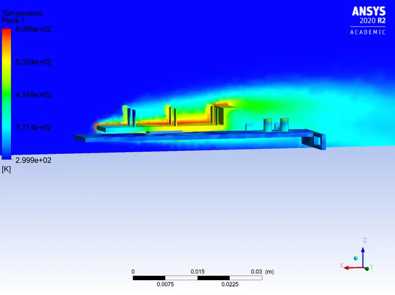
Temperature contour;
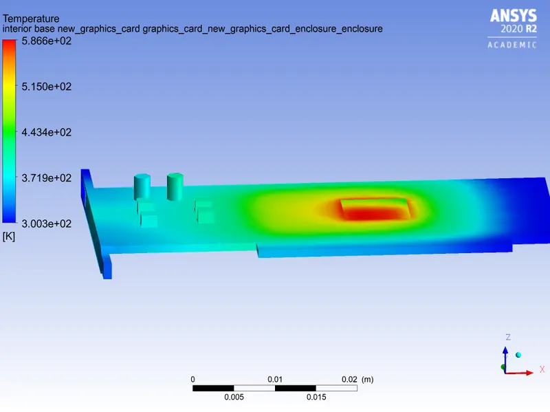
Temperature of base:
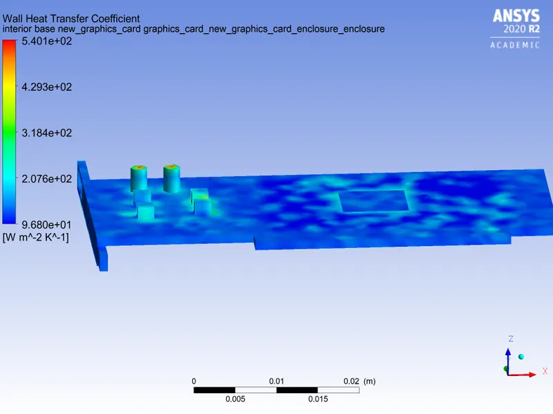
Wht of base:
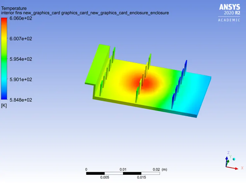
Fins temp
Fins wht:
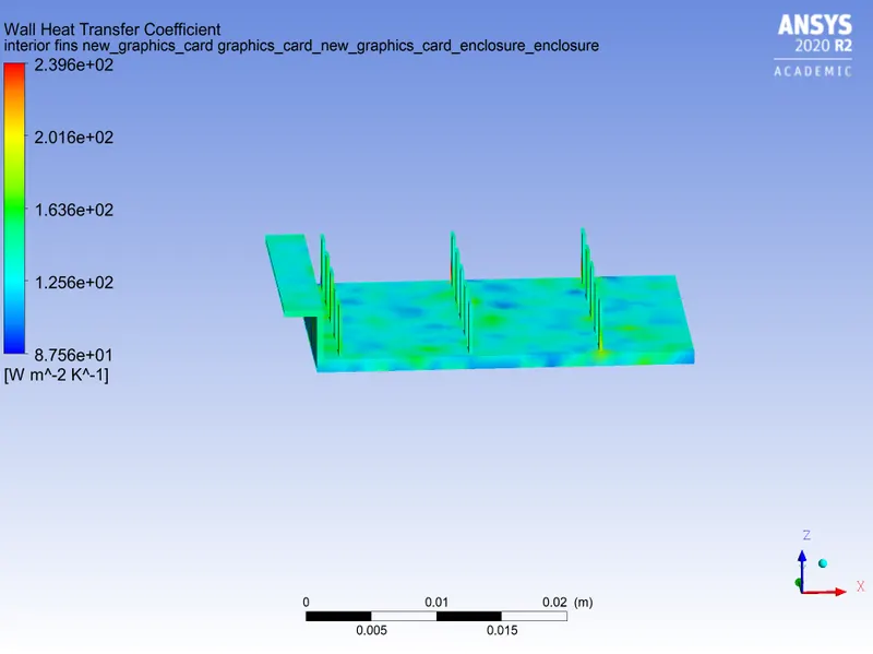
Cutplane Wht:
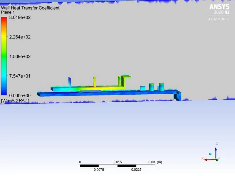
case(3):
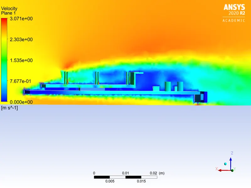
Velocity at 2.5m/s with refined mesh:
Residuals:
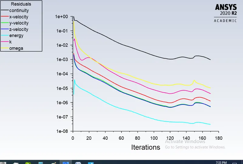
Temperature contour:
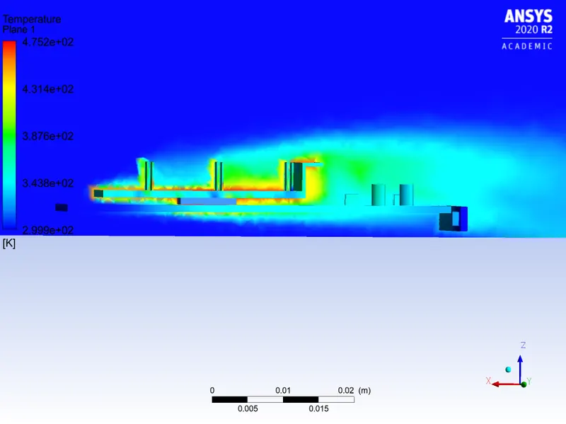
Velocity contour:
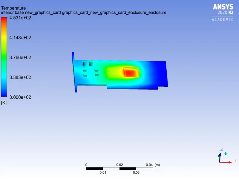
Base temperature:
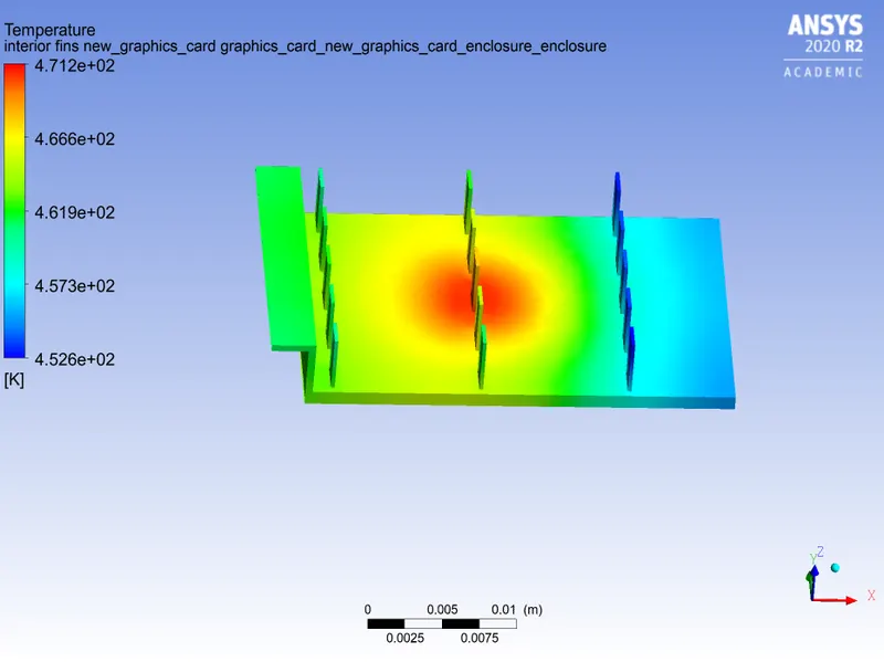
Fin temperature:
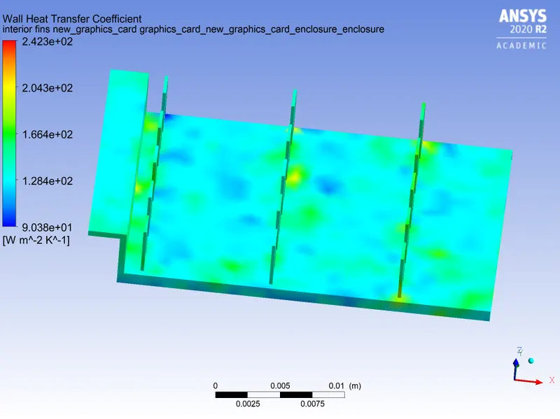
Fin wht:
cutplane heat transfer coefficent:
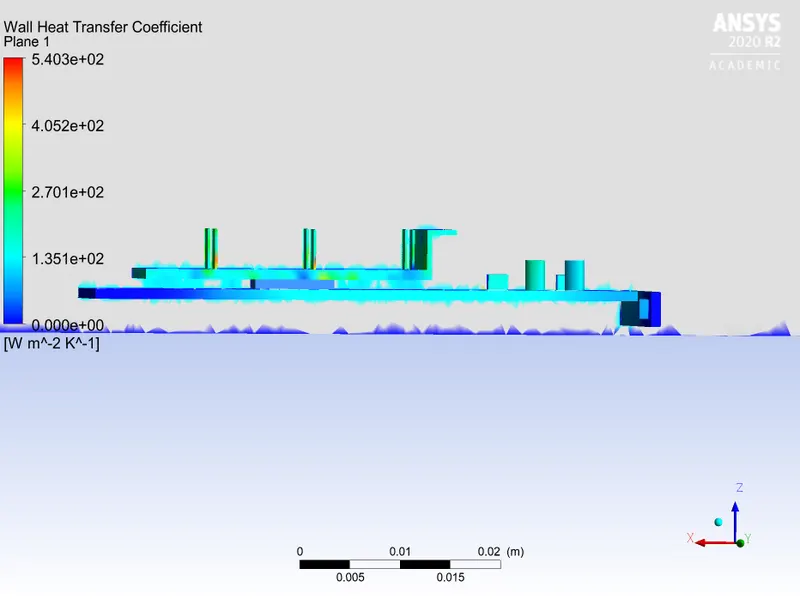
Case(4)
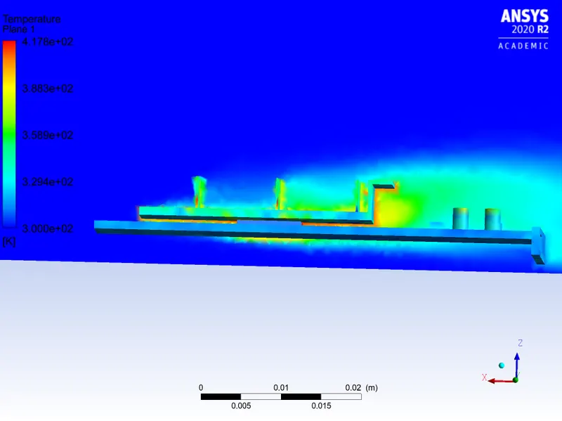
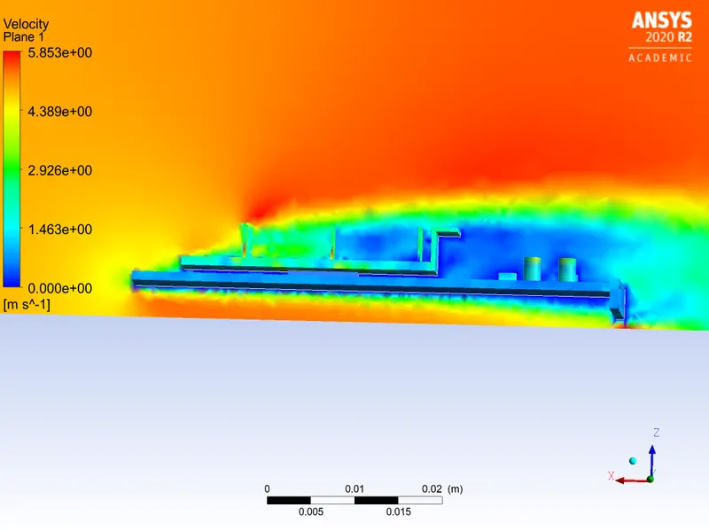
Velocity at 5m/s:
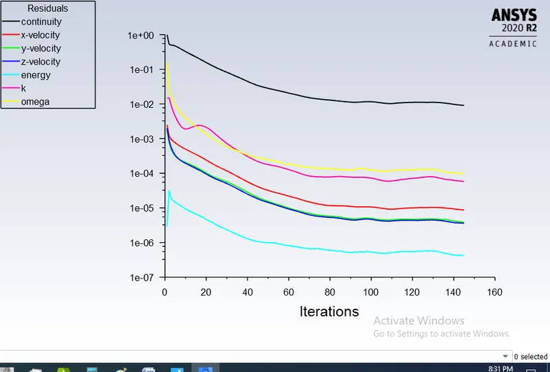
Temperature contour:
Velocity contour:
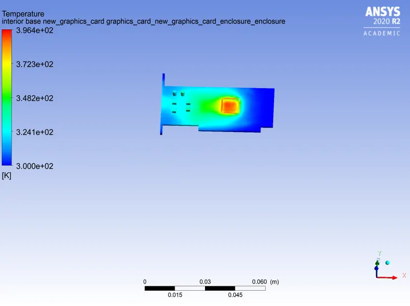
Temperature of base:
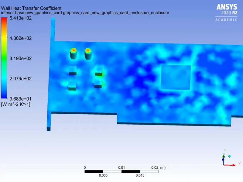
wht of base:
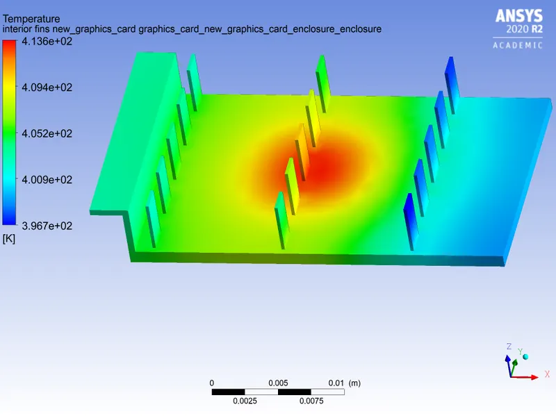
Temperature of fin:
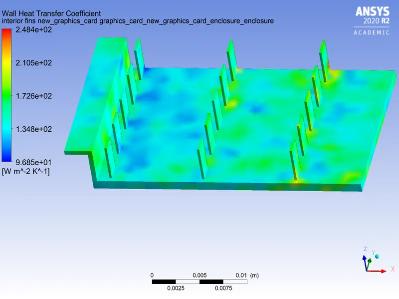
Wht of fins:
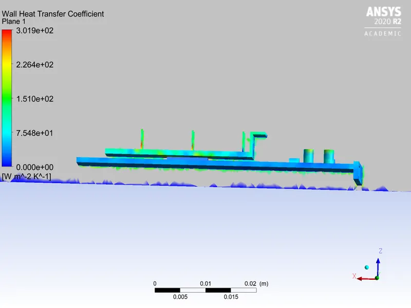
XZ plane of fin:
Observations:
| s.no | Velocity | Max temperature | Max heat transfer coefficent |
| 1 | baseline (v=1m/s) | 589.6 |
1138.69 |
| 2 | v=1m/s | 609.9 | 540.09 |
| 3 | v=2.5m/s | 475.2 | 540.266 |
| 4 | v=5m/s | 417.8 | 541.259 |
Conclusion:
1. With increase in velocity maximum temperature falls in conjugate heat transfer analysis of graphic card
2. Value of heat transfer coefficent depends on meshing
3. in base line mesh quality and statstics of mesh are low so we get different value compared to original value of heat transfer coefficent
4.Table shows a difference in base line mesh heat transfer coefficent compared to refined mesh
Hotspots:
1. we find hotspot in processor which is heat generation source and fins which transfer max heat from the graphics card are shown in above pictures.