Conjugate Heat Transfer Analysis on a graphics card.
GRAPHIC CARD SIMULATION
AIM :
To find out the conjugate heat transfer of a graphic card in fluent by using different mesh sizes and different velocities ,to see how the temeprature variation and velocity variation occurs .
INTRODUCTION:
As the graphic card consists of base,processor ,fins and pcbs .the purpose of the graphic card is to produce a image on the screen as we see .the garphic card is responsible rendering an to your computer ,it does this by converting the data in to the signal that which the computer can understand.As the processor which the does the whole process and funtion of the graphic card ,and their lot of heat is generated during the process .and for the cooling of the processor the fins are provided ,so that it increases the surface contact area and provides the cooling to the processor and the pcbs also do the process .
PRE-PROCESSING :
GEOMETRY :
In order to do the CHT process to the graphic card ,first we have import thre geometry to the spaceclaim .and after importing geometry into the space claim then go the workbench option in that ,click on the share preparation option then click ok then the each component share .
And after then go the mesh option for the mesh generation .
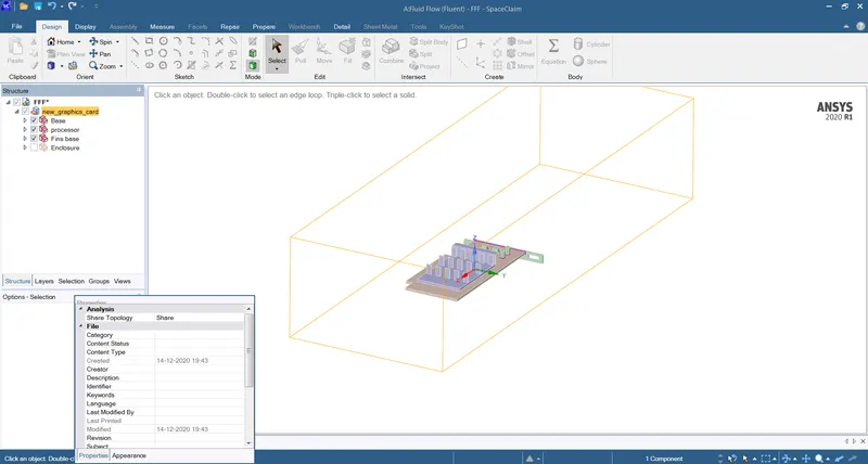
GEOMETRY IN THE SAPCE CLAIM
PROPERTIES OF MATERIALS
- Fins -ALUMINIUM
aluminium is available in the fluent data base
density :2719 kg/m3
heat capacity :871 J/kg k
thermal conductivity : 202.4 W/mk
- processor-silicon
silicon is not available in fluent data base ,i had define it
Density : 2000 Kg/m3
heat capacity :710 J/kg k
thermal conductivity : 150 W/mk
- base -steel
Density : 8030 Kg/m3
Heat capacity : 502.48 J/kg k
thermal conductivity : 16.27 W/m k
MESH :
MESH -10MM :
In the mesh we are going to create the named sections to the components in the geomerty.and after that with mesh size 10mm create mesh .
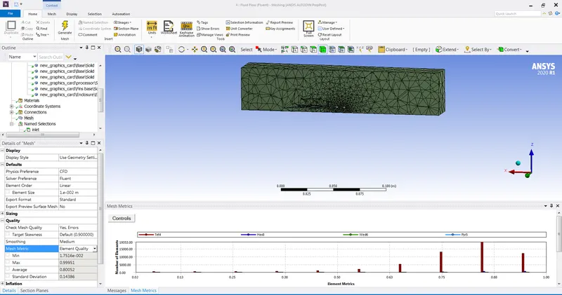
MESH WITH 10MM SHOWS THE QUALITY OF THE MESH
MESH -5MM
And again create mesh with 5mm
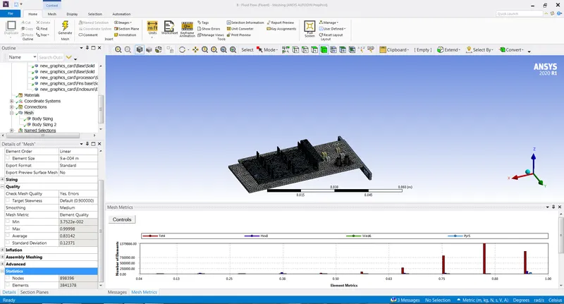
MESH 5MM
BODY MESH FINS -O.5MM
BODY MESH PROCESSOR -0.5MM
NODES -898396
ELEMENTS-3841378
the above figures shows the mesh generation and quality and nodes ,elements
SOLUTION :
After the mesh generation the go the setup solution process in the setup
we are going to use steady state -pressure based solver process
And using the energy eqaution and k-epsilon model Realizble
And then create materials of different based on the components materials used
Go the zones then add materials to the component and click ok ,make sure wheather you created the correct materials or not .
And after go the boundaries then give
inlet velocity as -3m/s and temperature as -500k
and in the zones go the processor add heat geneartion to the processor as it generates heat and main one .
the heat generation value is 2.8487e7 w/m3 .
and after that intialize the solution -hybrid and then caluclate it as per the required solution .
MESH 10- VELOCITY 3M/S SOLUTION PLOTS
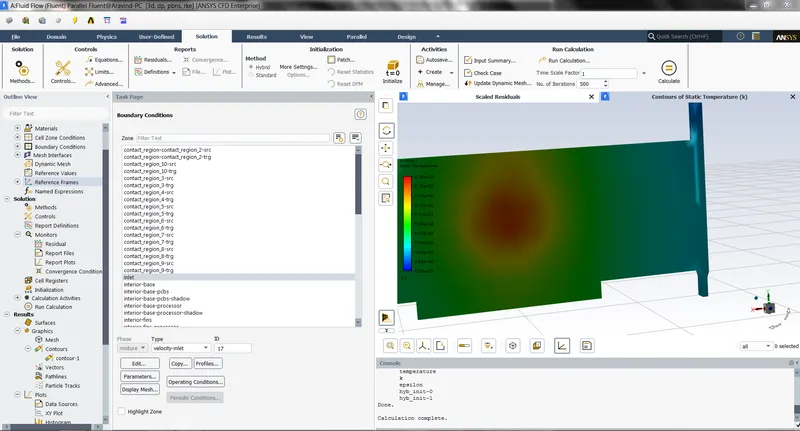
CONTOUR PLOT SHOW THE HOT SPOT ON THE BASE .
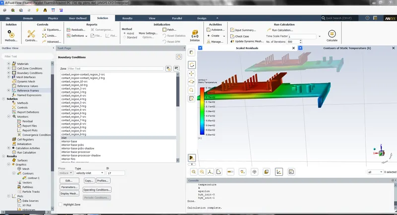
TEMPERATURE DISTRIBUTION FROM THE PROCESSOR TO THE FINS
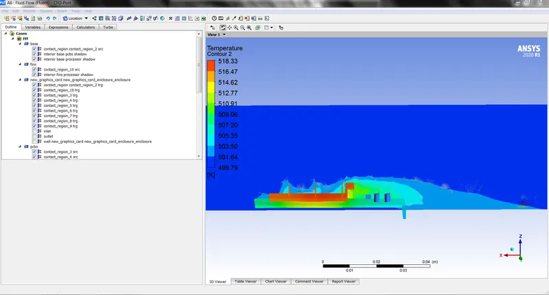
TEMPERATURE CONTOUR PLOT -MAX TEMEPRATURE -518.33
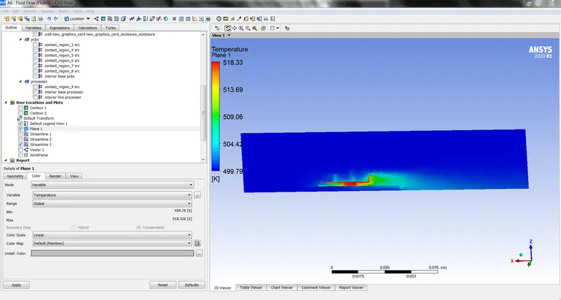
TEMPERATURE -ON PLANE
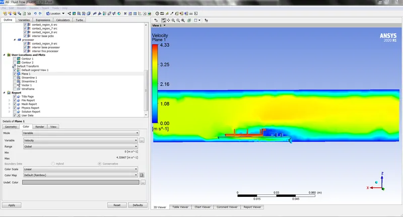
MAX VELOCITY -4.33M/S
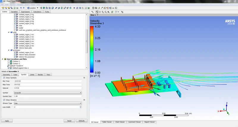
STREAM LINES OVER THE FINS
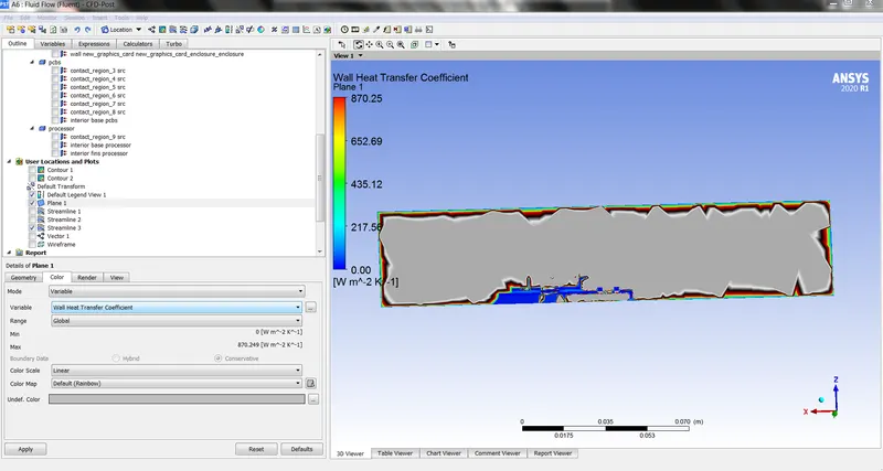
WALL HEAT TRANSFER COEFFICIENT
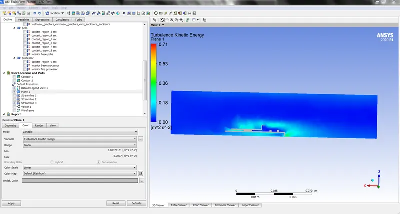
TURBULENCE K.E ON THE GRAPHIC CARD
VELOCITY -5M/S:
And the below figures show the vlocity with 5m/s and how the temperature and velocity varies .
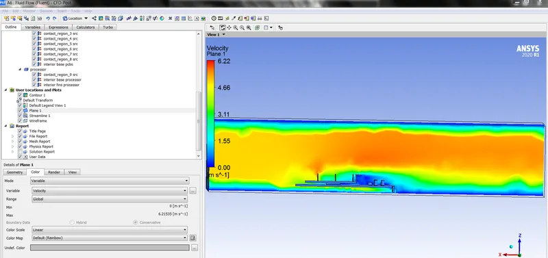
VELOCITY MAXIMUM -6.22 M/S
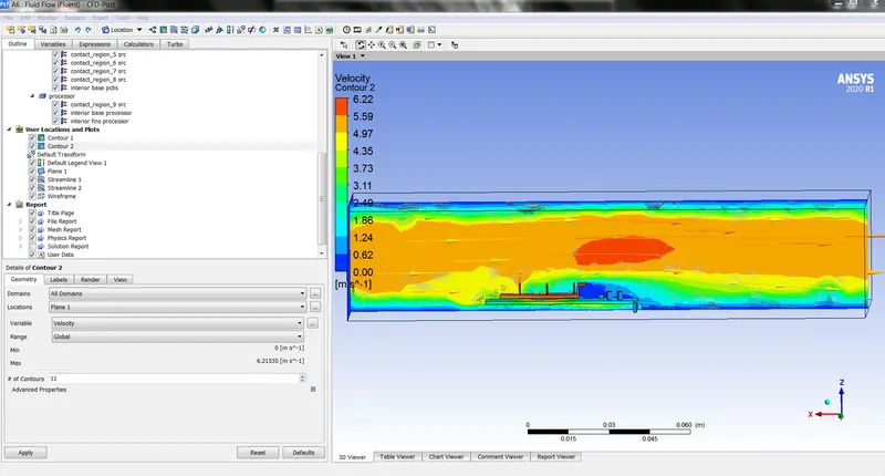
VELOCITY CONTOUR PLOT
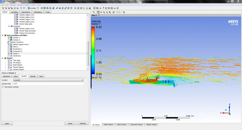
VELOCITY VECTOR PLOT
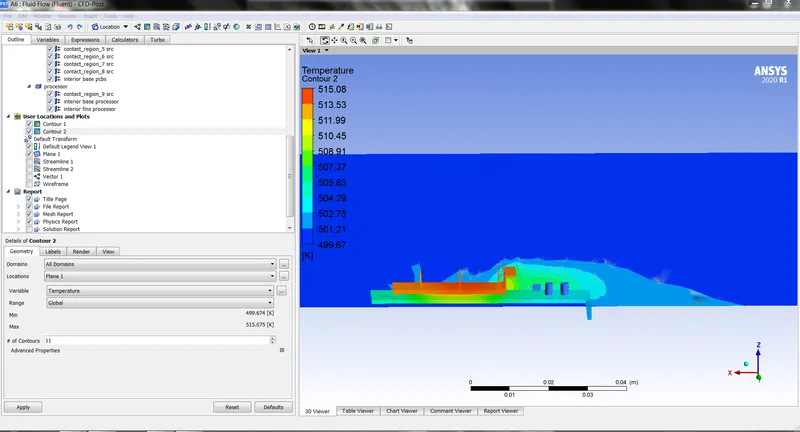
VELOCITY -5 -MAX TEMPERATURE -515.08K
MESH SIZE 5MM :
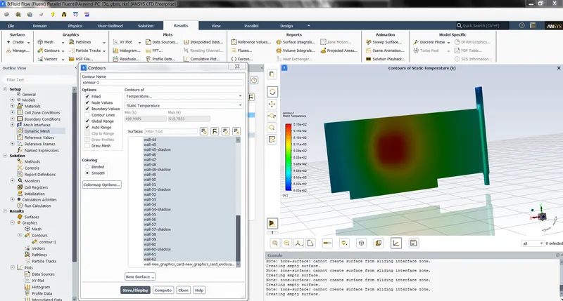
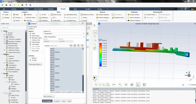
TEMPERATURE DISTRIBUTION HOTSPOT ON THE BASE
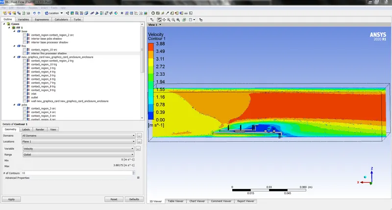
VELOCITY CONTOUR PLOT -MAXMIMUM VELOCITY 3.88M/S
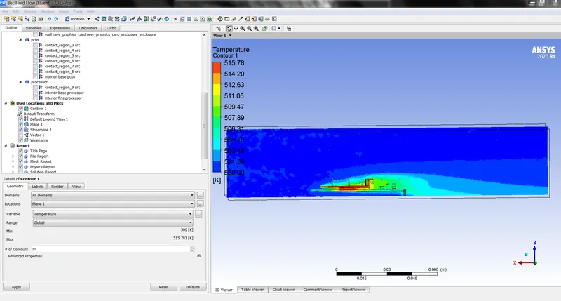
TEMPERATURE CONTOUR PLOT -515.78K MAX
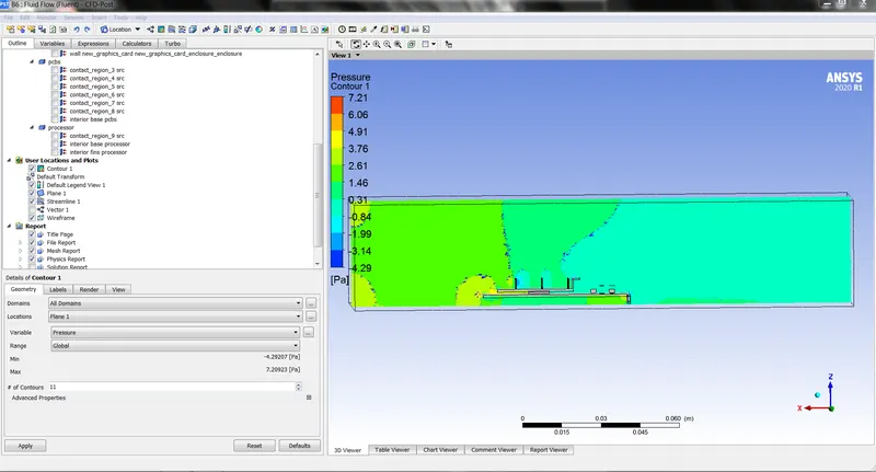
PRESSURE CONTOUR PLOT
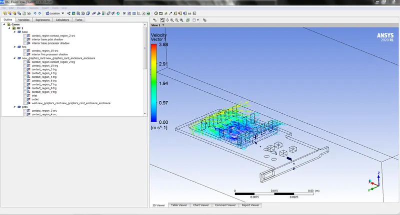
VELOCITY VECTOR PLOT ON FINS
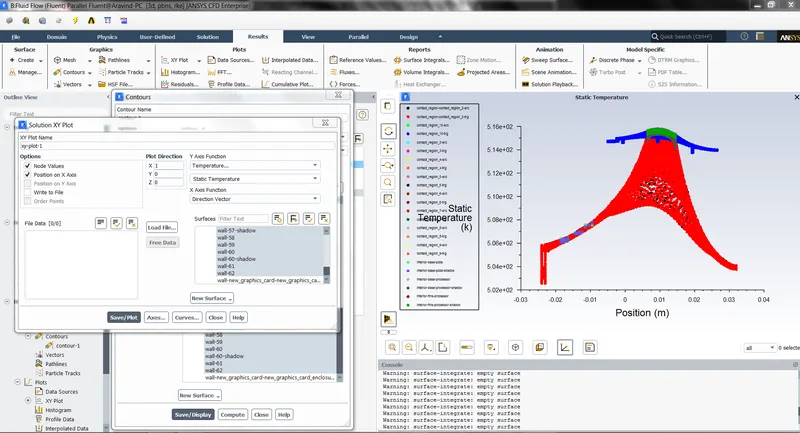
VELOCITY -5 M/S
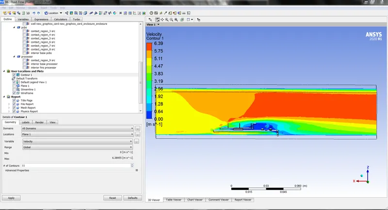
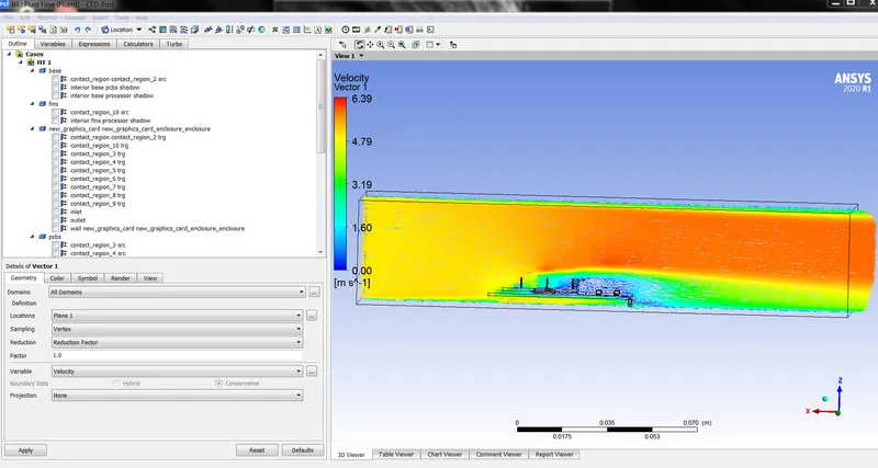
VELOCITY CONTOUR PLOT -MAX 6.39M/S
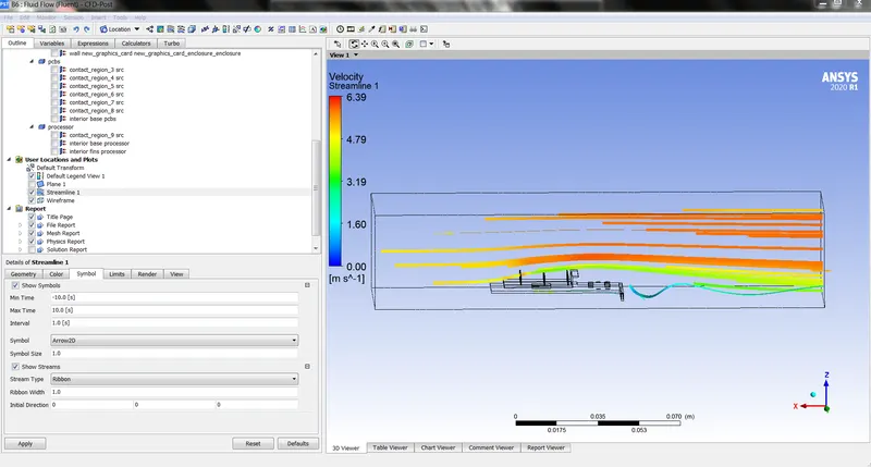
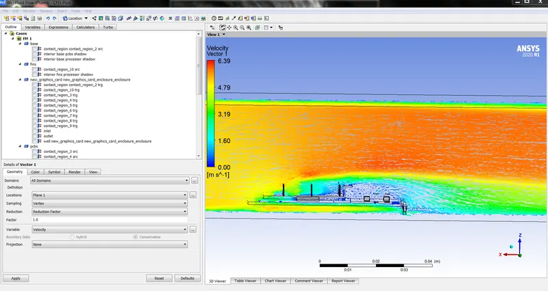
VELOCITY VECTOR
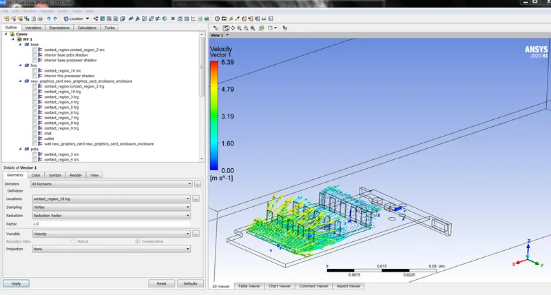
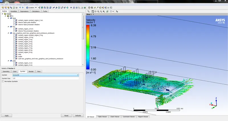
VELOCITY ON FINS -VECTOR PLOT
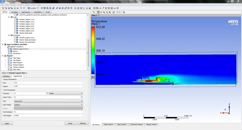
TEMPERATURE PLOT -512.30K MAX
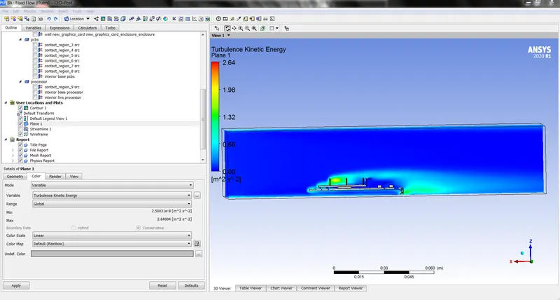
TURBULENCE KINETIC ENERGY
MESH REPORT: VELOCTIY 5M/S -5MM MESH SIZE
| DOMAIN | NODES | ELEMENTS |
| BASE | 159670 | 820812 |
| FINS | 124139 | 609872 |
| ENCLOSURE | 410787 | 2184696 |
| PCBS | 1736 | 1322 |
| PROCESSOR | 252810 | 224676 |
| ALL DOMAINS | 949142 | 3841378 |
MESH REPORT :VELOCITY 3M/S -5MM MESH SIZE
| DOMAIN | NODES | ELEMENTS |
| BASE | 159670 | 820812 |
| FINS | 124139 | 609872 |
| ENCLOSURE | 410787 | 2184696 |
| PCBS | 1736 | 1322 |
| PROCESSOR | 252810 | 224676 |
| ALL DOMAINS | 949142 | 3841378 |
As we seen above ,the results we got by simulating at different velocities and different mesh sizes .And now we are going to discuss the above results we got
coming to the base mesh size 10mm
if we observe the results from the plots at 3m/s velocity ,we have seen less heat transfer from the surface and after increasing the velocity about 5m/s thier is more heat transfer from the surface
this we can observe from the temperature plots how the heat transfer vary from the surface at different velocities .
And after then refining the mesh size to 5mm ,we can see the difference at 3m/s and 5m/s velocities
by this we can make a point that by increasing the velocity their will be the maximum heat transfer occurs ,that the fluid can take away the maximum amount of heat that produced by the processor through fins
And the hot spot we observed in the graphic card is in the base and the fins are mainly effected or the more amount of heat taken by them from the processor .
| MESH SIZE | VELOCTIY | MAX TEMPERATURE | MAX VELOCITY |
| 10mm | 3m/s | 518.3k | 4.33 m/s |
| 10mm | 5m/s | 515.08k | 6.22 m/s |
| 5mm | 3m/s | 515.78 k | 3.88 m/s |
| 5mm | 5m/s | 512.30 k | 6.39 m/s |
CONCLUSION :
coming to the concluison,by doing mesh refinement we can get the accurate values as we have been observed from the plots and there will be a lot change in the results we got before refinement and after refinement.by doing this project i have learned how to do a simulatioin process on graphic card and aslo how to add the heat soure to the components .and i got an clear view of how the heat transfer takes place in the component and how the flow occurs.