Conceptual design of a building with columns and shear walls
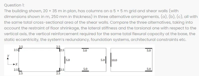
Ans.1
- Restraint of floor shrinkage :
Case 1
- In this case, since the shear walls are placed at corners, it has good restraint against floor shrinkage.these shear walls at the corner will tightly hold the floor in position and shrinkage will be in control.
Case 2
- Here the shear wall are placed along the wall in all four sides.The wall will provide better stabality to the floor near the corner portion of the floor are subjected to shrinkage where there is no shear walls.
Case 3
- Here since shear wall are not placed symetrical. Both the long edge and right edge of the wall is prone to shrinkage as therre is no shear wall at right side along the long edge the shear wall placed only at right most edge.
- Lateral Stiffness :
Case 1
- As a shear wall are placed at center of floor, the edge of floor does not have any support and since the earthquake force or sesimic forces tends ta act along the edge of the floor, this placement of shear walls have least stabality and hence the lateral stiffness will also be less.
Case 2
- Here the shear wall are placed along the edges which is same direction of earthquake excitation,the structure will have more stabality and as such the lateral stiffness will also be more along both the principle planes.
Case 3
- Here along x direction, there are two shear walls which enhance the stiffness in that direction, whereas in the y direction, there is only one shear wall at the left which leads to the concentration of sesimic force in that wall and cause instabaility and reduce the lateral stiffness in that direction.
- Torsional Stiffness with respect to vertical axis:
Case 1
- Here placement of shear wall is symetrric, hence no eccentricity between centre of mass and centre of stiffness, both coincide, so its less prone to torsion and can be regarded as tortionally stiff model.
Case 2
- In this arrangement also, the placement of shear walls is symmetric and there is no eccentricity between the centre of mass and centre of stiffness. Hence, thi arrangement is also less prone to torsion
Case 3
- In this arrangement the shear wall placement is unsymmetrical along the y-direction. So, the centre od stiffness shift towrds the left edge and as such there is an eccentricity between the centre of mass and centre of stiffness which leads to torsional instabality in this arrangement.
- Vertical reinforcement required at base:
Case 1
- As the shear reinforcement are placed at the corners, it does not take part much in resistance of the lateral forces as compared to other parts of wall.As such the amount of reinforcemnt required for these wall will be less.
Case 2
- Here the huge amount of lateral forces are taken by these shear walls as they are placed along the principal direction itself.hence, these walls should be provided with much more reinforcemnt to resist these forces.
Case 3
- In this arrangement the shear wall are asymmetrical placed along, large amount of lateral forces will be taken by the shear walls especially the walls at left edge.Hence, these walls needs to be heavily reinforced.
- The static eccentricity :
Case 1
- In this arrangement also, the shear walls is symmetrically placed at the coreners, the centre of mass and centre of stiffness coincedes and there is no eccentrcity.
Case 2
- In this arrangement also, the shear walls is symmetrically placed along the edge, the centre of mass and centre of stiffness coincedes and there is no eccentrcity.
Case 3
- Here the shear wall are symmetrically placed along one of the principal direction i.e.X-direction, but in the Y-direction there is only one shear wall along the left edge with heavier mass compared to other two shear walls.due to this, the centre of stiffness shifts to left side and hence, there is eccentricity in the arrangement.

Ans.2
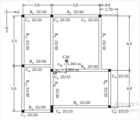
- Any single plane frames should run contineously from one side of the building plan to other , without offsets, interruptions (missing beams between adjacent coulmns in a floor),or indirect supports of beams on other beams.
- If a beam does not continue straight from span to span, but its axis is offset at the column between them, there is no smooth flow of internal forces through a proper beam-column joint, neither continuity of the beam longitudinal bars across the column from one span to next these bars have to terminate there and be seperately anchored at the joint.
- Even when the beam axis is not offset from span to span, the smooth flow of internal forces from the beams to the column is impaired by a large eccentricity between the axis of the beam and supporting column.
- If a beam terminates at an (indirect) support on another beam, there is large uncertainity concerning its rotational restraint by the support beam via torsion in latter. In approroximation, an indirect support may be considered as a simple support; the indirectly supported beam is less effective in frame action than one connected to coulmns at both ends.
- Beam with long span may have their top reinforcement at supports governed by factored gravity loads, rather than by the sesimic design situation.
- This result in beam over strength, relative to the moment demand in the sesimic design situation.
- the overstrength is carried over to the capacity design shear of beam or the columns, penalizing them and creating some uncertainity wheather plastic honges will form in the beam or the columns. there is possibility of plastic hinge occuring away from face of column.
- Beams with low span-to-depth ratio (less than4) have to be dimensioned for high shear forces,from the sesimic analysis or from capacity design in shear.unless diagonally reinforceed, short beam have low deformation capacity and poor ductility.
- For the reasons detailed above, short beam span should be avoided, while span of 4 to 6m should be preferred over longer ones, at least for the storey heights and gravity loads commonly encountered in buildings.
Ans.3
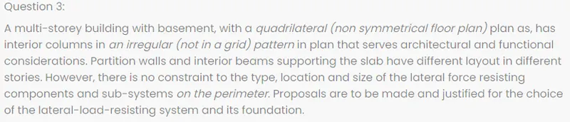
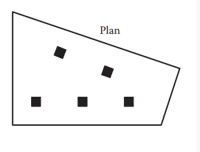
- The general layout and certain details of the geometry (shape, size and typology) of an idividual plane frame have a major impact on its sesimic behaviour.very important also is the overall layout of the frame in a structural system.
- The location of frame in plan and their span lengths are normally governed by architectural and functional considerations, while beam depths may be controlled by design for factored gravity/sesimic loads.
- Nevertheless, the structural designer is essentially free to choose the all important geometric details of individual plane, frames and has certain freedom concerning their overall geometry and location in plan.
- Frames place few constraint on building architectural design, including the facade and parking spacein the ground floor.
- Frames may be cost-effective for eathquake resistance, beacause beams and columns are placed anyway for gravity loads, so they may also provide earthquake resistance in both directions, if their columns are large.
- frames with concentric connections and regular geometry have well-known and understood sesimic performance.
- It is easier to design an earthquake-resistant foundation element for a smaller vertical member than for a larger one.
- Frames are inherently flexble, the cross section of their members may be governed by the inter-storey drift limitations under the moderate earthquake for which limitation of damage to structural and non-structural elements is desired.
- Column counter-flexure in the same storey allows soft storey mechanism, which lead to collapse.
- Earthquake-resistance requirements on frame lead to large columns, interferng with archutectural functions.
- The reinforcement detailing of frame for ductility requires workmanship of high level for its execution and good supervision on site.
- Thwe walls and frame system each have their advantage and disadvantage as lateral load resisting systems.
- Walls seem to have a better balance of advantage against drawbacks, nevertheless, a concrete building always has beams and columns to support the gravity loads, it is a waste not to uses them for earthquake resistance.
- Therfore frames and walls may well be cost-effectively combined in a single lateral load resisting system.