Conceptual design of a building with columns and shear walls
Ans 1
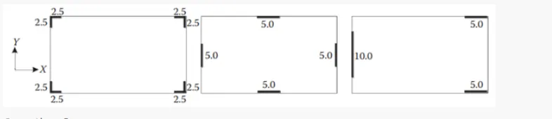
Numbering from left to Right as 1, 2 & 3 as follows1:
| S.no. | Characteristics of Plan | Layout plan 1 | Layout plan 2 | Layout plan 3 |
| 1.0 | restraint of Floor Shrinkage | Observation: Shear walls are distributed at all the Four Corners of the Property Line | Observation: Shear Walls are provided along the edges at the middle of the walls. | Obervation: Shear Walls are scattered around all the periphery. |
| Conclusion: As per Westguard's Formulae of Warping Stresses, stress at corner is maximum resulting in prevention of Expansion of Concrete corner slabs at the floor level, which may lead to temperature cracks at the corners of the building. |
Conclusion: Westguard's Warping Stresses at: (corner)>(edge)>(interior) At the Edge of the building, Stresses are not much higher than at the corners resulting in Better arrangement than before. |
Conclusion: Non Uniform layout plan of the Shear wall results in scattered distribution of wraping stress around the walls. |
||
| Conclusion: 2nd plan is Better | ||||
| 2.0 | Lateral Stiffness | All the Corners of the Building are provided with the Shear walls resulting in symmetrical & Equivalent Lateral Distribution along the middle of the layout plan in both the Axis. | All the Edges at the middle of the walls are provided with Shear Walls resulting in better arrangement of shear walls as these can be combined more effectively with Frame system of the building monolithically. | Though Shear Walls can be combined with the Framing system of the building but Non-Regular pattern around both the Axis resulting into weaker distribution of Forces. |
|
Conclusion: 1st & 2nd Plan are equivalent in terms of Lateral Stiffness but 2nd plan can more effectively combined with framing system of the building resulting into more Lateral Stiffness. |
||||
| 3.0 | Torsional Stiffness: | More Torsionally Stable configuration because stress are maximum at the places of maximum distance from the the core of the building. | torsional stresses are maximum at the maximum distance from the core, but here no lateral system is provided at the corners. |
Non- Unifrom pattern. Govering Eqn. : stress=(My/Ipy)*r where;My= Torsional moment along Y axis Ipy= MoI of Shear Walls along Yaxis at Center of Rotation r= radial distance from center of Rotation. |
| Conclusion: 1st is best. | ||||
| 4.0 | Vertical R/f reqd. for the same Flexural Capacity | L- type foundation cannot be clubbed with foundation of framing system until & unless Box Type foundation around the periphery of the property line is adopted, resulting into more vertical R/f for the same capacity. | shear walls can be easily clubbed with the framing & foundation of Beam Framing sytem resulting into better arrangement. | Scattered pattern of the Shear walls along three edges resulting into unstable configuration. |
| Conclusion: Requirement of Vertical Steel:3>1>2 | ||||
| 5.0 | Static Ecentricity: | Symmetry along both the axis. | Symmetry along both the axis. | Ecentricity exist along both the Axis. |
| 6.0 | System Redundancy Re | Due to L type foundation, Shear walls can not be Effectively combined with framing system of the building. | Shear Walls are better arranged with Framing System resulting into more redundant configuration. | Non-Parallel lateral Force Resisting System (Plan Irregularity of Table 5 of IS 1893:2016) |
| COnlusion: 2nd system is better in terms of System redundancy. | ||||
| 7.0 | Foundation System: | Box Type around the periphery of the property line is mandatory to get Monolithic connection of lateral resisting components. | No any special foundation is required, therfore, Shear walls can be easily clubbed with framing Foundation of the Building Frame. | Foundation Sytem can not be conceived due to irregulrity in plan configuration. |
| Conclusion: 2nd Option is better & Economical to be adopted. | ||||
| 8.0 | Architectural Viewpoint | This system is most Favorable from the Architectural point of view. | Higher chances of Obstruction as higher sides of the walls are captured by the Shear walls. We can not provide any significant opening within this frame. | Ideology can not be supported. |
| Conclusion: 1st is most Favourable. |
-------------------------------------------------------------------------------------------------------------------------------------------------------
Ans 2:
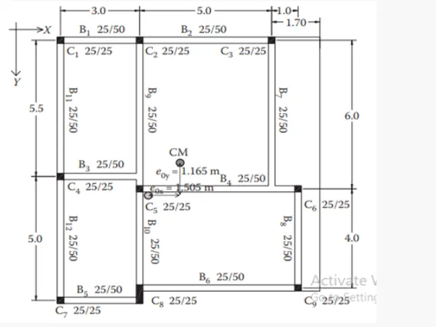
| S.No | Characteristic 's | Remarks |
| 1. | torsional flexibility | eoy & eox are the ecentricities b/w CG (Center of gravity) & CR (Center of Resistance) of the Building.Therefore, Torsional Flexibility will definately exist along both the axis. |
| 2. | Lateral Force Tranfer | |
| along X- Axis | Beams running along the Xaxis are not perfectly aligned along the shortest path of lOad Transfer. Therefore, stress Concentration comes into existence in b/w (B3&B4) & (B5 & B6). | |
| Along Y axis |
Beams Running along Y axis are aligned along the shortest path,except at a junction of (B7 & B8). C6 & C9 are provided at an offset of 1m will not be able to transfer proper force along Y axis, resulting into Stress Concentration at (B7 & B8). |
|
| 3. | Beam & column Methodology | Beams(25*50) * column(25*25); strong Beams & Weak column problem might be possible until& unless Column R/F have not been enhanced. As we don't have any R/f detailing, so assuming the R/F in Beams & Columns to be Equivalent, it can be manifested that Strong Beam & weak Column will exist. |
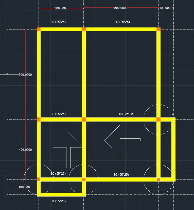
By Moving the Columns along inner side by Distance of 1 m, we have been trying to solve two aspects:
1. Shifting of CR from the left side to slightly Right & from the Down to upper Side of the building Plan.
2. Aligning Beams along the Shortest Path to Transfer the Lateral Forces without any possibilty of Stress Concentration.
==================================================================================
Ans 3:
Observation:
1. Unsymmetrical plan about both the axis: As the Floor Area is unsymmetrical about any of the Axis. Therefore, any layout plan of columns will not be able to resist the lateral Resisting Force in a building. To resist the Torsional Flexibility, we have to adopt a different Layout plan of Beams & columns.
2. Random Alignment of Columns: Connecting any layout in floor beam will not be sufficient enough to transfer the lateral forces along any of the shortest distance of path. Therefore, Lateral Loads within a frame cannot be resisted by Beam-Column web. Columns are designed to carry the Vertical Loads in a building.
3. Partitions Walls & Interior Beams have different Layout: Partition walls have significant mass on a specific storey whose Structural Plan Density (SPD) if increases by 20% of Storey mass, lead to Stiffness Irregularity in a storey.
Interior Beams have the main role in transfering the Shear & Gravity loads from the slab to columns. If the layout plan get scattered storey to Storey, Uniform Distribution along the shortest load path can not be possible resulting in Higher Modal mass at higher Frequency. (Irregular Modes of Oscillation in Two Principal Directions: Table 6 of IS 1893:2016)
Conclusion:
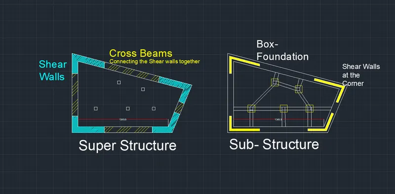
As Columns are Designed to Carry the Vertical Loads while Lateral Force within the Frame has resisted through Shear walls provided at the property line of the Building.
As two systems are designed to carry two different forces but their action acting on a building through collaboration or acting simultaneously in a building Frame.
Therefore, Box Type Foundation is provided to bridge the two reaction into a single reaction(resistance).
====================================================================================