Conceptual design of a building with columns and shear walls
1.
1.1.Restraint of floor shrinkage:
- Arrangement A: Four shear walls are provided at the corners of the wall and because of the positioning of the shear wall, they provide full restraints to the corners. Therefore the floor will be held tightly in place and the shrinkage will be controlled.
- Arrangement B:Shear walls are at the centre of wall on all four sides.So the shrinkage can occur at the corner of the walls but not at the centres.
- Arrangement C:The floors prone to shrinkage since the walls are not symmetrically arranged.
Conclusion:
Arrangement A will have maximum restrain and is prone to cracks followed by B and then C
1.2.The Lateral Stiffness:
- Arrangement a:Since the walls are positioned at the corners of the walls and seismic forces tend to act along the edges of the floors it will have low lateral stiffness .
- Arrangement B:Shear walls along the edges will have better stability and better lateral stiffness along X and Y Axis
- Arrangement c: In X direction the lateral stiffness is high since there are two shear walls and in Y-direction it will only concentrate earthquake forces since it has only one wall.
CONCLUSION:
Arrangement ‘B’ will provide highest lateral stiffness .
1.3.Torsion with respect to vertical axis:
- Arrangement A :Walls at the corners of the walls provide best resistance aginst twisting.
- Arrangement B :Shear walls positioned along the edges provide good resistance against twisting.
- Arrangement C :They provide the worst resistance against twisiting due to its irregular positioning.
1.4.Vertical Reinforcement at the base:
- Arrangement A :These walls will require a huge amount of reinforcement since they are positioned at the corners of the walls and are subjected to heavy twisting moments and small bending moments.
- Arrangement B :Reinforcement should be added to these walls to withstand the lateral forces since the shear walls are positioned along the main directions. They attract lesser twisting moments and small bending moment.
- Arrangement C :Due to their irregularity they will attract larger force hence should be heavily reinforced.
CONCLUSION:
Arrangement ‘C’ will require the highest vertical reinforcement followed by A and B.
1.5 Static eccentricity:
- Arrangement a:As the shear walls are positioned at the corner of the walls , there is no eccentricity.The centre of mass and the centre of stiffness are same .
- Arrangement b:As the shear walls are positioned at the centre of the walls and are symmetric,there is no eccentricity.the centre of mass and the centre of stiffness are same
- Arrangement c:As the shear walls are positioned unsymmetrically there would be a significant amount of eccentricity in the given case. The centre of stiffness is towards the left side of the given plan.
- Foundation system:
(a) Arrangement a:
The shear walls are placed at the corner of the walls therefore, the geometry and design of the foundation would be critical. We ought to provide box type foundation in this case as the walls are placed in an L shape.
(b) Arrangement b:
In this layout the shear walls are placed in a straight line hence the geometry and design of the foundation would be simple we can use an isolated or strip raft foundation for this system.
(c) Arrangement c:
Shear walls are unsymmetrically placed but in a straight line hence the geometry of the foundation would be simple but designing of foundation would be critical as they attract a large number of lateral loads.
CONCLUSION:
After the above discussion arrangement ‘b’ and arrangement ‘c’ should be provided with isolated and strip footing.
And arrangement ‘a’ is recommended to have a box foundation.
1.7Architectural constraints:
- Arrangement A:The walls are symmetrical . These walls do not obstruct with any architectural design
- Arrangement B:These walls are arranged symmetrically but these walls may obstruct entrances with the architectural design.
- Arrangement C:The two walls on the right side are good however the vertical wall obstructs access to the building. It may clash with the architectural design.
CONCLUSION:
Arrangement ‘A’ is the most preferable one followed by arrangements ‘B’ and ‘C’.
8,System redundancy:
- Arrangement A :Shear walls that are positioned at the corner of the walls are symmetric and uniform hence the system is redundant.
- Arrangement B :The shear walls are arranged at the mid-portion of the walls and are symmetric and uniform so they experience the forces equal in both directions.
- Arrangement C :The shear walls are positioned asymmetrically in the Y-direction, so Y-direction will lead to the concentration of a large number of lateral loads on the left side of the layout so it has poor redundancy.
CONCLUSION:
Arrangement ‘A’ and ‘B’ are more redundant than ‘C’.
____________________________________________________________________________________________________________
2.Observation of given system:
Moderate earthquake will affect this structure due to its complexity in load transferring mechanism as discussed below
- Column C8 is made big to incorporate beam B6
- Beam B3 and B7 is attached to other beams and not column making it hard to tranfer load.
- The beams are stronger than the column members not obeying capacity design philosophy.
Alternative structural framing:
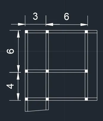
The plan is made to effectively transfer thr loads of beam to column effectively.
Torsional impact of the building:
- The centre of mass and centre of stiffness of the building are not same so the building will experience torsional moments in both X and Y directions. but the plan ratio is less than 3 by IS1893 hence we can assume the given system is well proportioned.
- The given structural floor system is not effective in transferring lateral loads to vertical elements due to irregular beam-to-column connections. The response of building in the fundamental mode of translations is also not effective.
- The two fundamental modes of translation is higher than the fundamental mode of torsion.
______________________________________________________________________________
3.
- The columns in this layout are not symmetrically arranged.
- The plan is an asymmetric quadrilateral.
- Columns and beams are not in a regular grid pattern.
- They can resist gravity loads but they can’t resist the lateral load because of the no symmetry.
Alternate Plan:
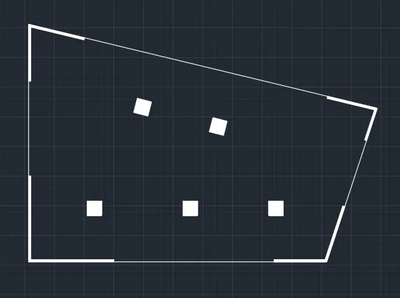
Earthquake affecting X-direction earthquake will also affect Y-direction. So a lateral load resisting system of L shaped shear wall system is given to increase lateral resistance of all sides.
We can use isolated footings with tie beam connections or box type foundation.