Conceptual design of a building with columns and shear walls
1.
a)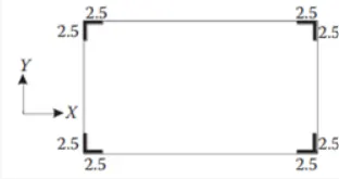 b)
b)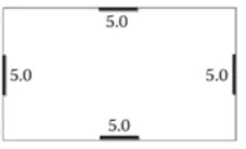 c)
c)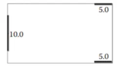
The lateral stiffness:
- As we can observe from plan a, they have low lateral stiffness because wall are provided at the corners when the loads are applied in X and Y direction
- Uniform and comparatively higher lateral stiffness in both X and Y axis, because the wall are provided at the center of both the axis
- Non unifrom walls are provided, causing poor lateral stiffness.
Conclusion:Plan b will provide higher lateral stiffness for a pure seismic accleration in X and Y direction.
Restraints of floor shrinkage:
- Full restraints at all the corner in plan a
- Corners are left free but restraints along the edges
- Non unifrom restraints
Conclusion:Plan a will have higher restraints in shrinkage, thus leads to cracks in the floor,Plan c will hav less crack
Torsion with respect to vertical axis:
- Plan a will provide more resistance for torsion, as the wall are provided at the edges.
- Plan b will provide resistance to torsion but not as much as plan a
- Plan c have irregular wall, which cause poor resistance to twist.
Conclusion: Plan a will provide more torsional resistance because it is restrained in alll four directions.
System's redundancy:
- The placements of the shear walls are uniform and the lateral loads are equally shared in plan a and b
- But in option c there is a concentrated lateral loads in both the axis.
Conclusion: Plan a and b are more redundant than plan c.
Static eccentricity:
- Both plan a and b are structurally symmetric
- Plan c is un-symmetric.
Conclusion: Plan c will have static eccentricity.
Foundation systems :
- Due to "L" shaped walls the geometry of the foundation and its design will be critical, in plan a
- Walls are in line geometry will be simple and the design also will be simple in plan b
- Walls are in line easy to fix the geometry but critical in design.
Conclusion: paln b and c shall be incorporated with isolated and strip footing, plan a is recommended to have peripheral box foundation.
Architectural constraints:
- As we can observe in (plan a) the walls are obstructed at the corner, there will be less arcitectural constrains
- The wall are placed in centers for both the directions. There will be obstruction in the architectural plan
- The wall which is placed at left covers that part so this type will not be accepted architecturally.
2.
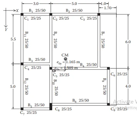
Indirect lateral load transfer in X and Y direction :
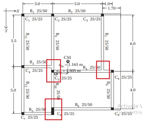
- From the above picture we can observe that the horizontal beam is not connected to column directly,so the lateral load are directed to the main beamwhich causes shear failure in main beam.In y direction also the beam is resting on the other beam which causes shear failure.
Eccentricity:
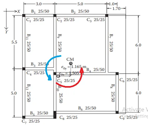
- There is a longer distance between center of mass and center of stiffness in both X and Y direction. The longer the distance between center of mass and center of stiffness, the higher torsional moment of the building.
Conclusion: The building is subjected to higher torsional moment.
Strong beam week column possibilties:
The size of the column(C1)is 25cm*25cm,but all the beam have much deeper section(50cm).Inertia of beam is visually higher than column.If the column reinforcemenet is adquately greater than that of beams,since we dont have reinforcement details,this is doubtful. It is recommended to have slight bigger size of column.
Conclusion:
The columns can be re-arranged
3.
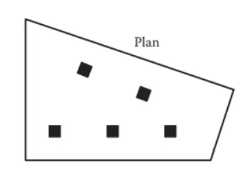
Floor Plan:
- The floor plan is neither uniform nor symmetric, so any lateral load including floor load will not have 100% influence in same direction (bi-directional).
The proportion of floor area is greater on the left side than the right side, so corner shear walls on the left side should be heaviour than the right.
Corner shear walls can be preferably be supported over box foundation. Shear walls should be connected by link beams to transfer shear from one to another.
Random internal columns:
- As we can observe from the above plan, the internal column are randomally placed without any grids.
- Because of the random placements of the column,they were unable to transfer lateral load efficiently.
Internal columns shall be supported by isolated footings and those footings can be connected with shear walls through tie beams.
Floor to floor variation in partition walls and beams:
Partion wall which carries mass and beams plays a key role in tranfer of shear loads from floor to beam are not given properly in the plan.So heavy distortion and displacement of lateral load will take place.
- Irregural quadrilateral is observed from the floor plan, which will be unable to resist earthquake