Conceptual design of a building with columns and shear walls
1Q]
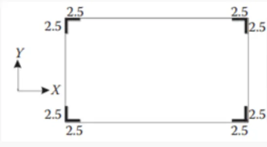
Plan (a)
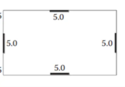
Plan (b)
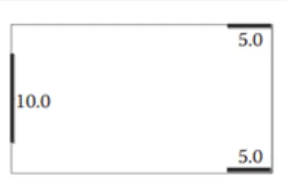
Plan (c)
AIM: -
To Compare the three alternatives, considering the following elements.:
- The restraint of floor shrinkage
- The lateral stiffness
- The torsional one with respect to the vertical axis
- The vertical reinforcement required for the same total flexural capacity at the base,
- The static eccentricity
- The system’s redundancy
- Foundation systems
- Architectural constraints
PROCEDURE: -
- The restraint of floor shrinkage
For slabs on ground, it is the friction on the soil that presents the main cause of shrinkage.
In the case of concrete repairs and thin bonded overlays, restrained shrinkage results from the bonding on the substrate concrete.
For all of these structures, the absence of shrinkage cracks is very important for long-term durability.
Restrained shrinkage cracking occurs when concrete is prevented from making volumetric changes by a source of restraint.
Volumetric changes in concrete result from creep, shrinkage of the concrete, or thermal loads.
In the given plan (a), all the four corners are restrained by the columns and shear walls
(5m * 5m grid and 250mm thickness).
Cracking occurs because concrete is prevented from making volumetric changes by these shear walls restraint.
In the given plan (b), all the four corners are not restrained but restrained along the edges by the columns and shear walls (5m * 5m grid and 250mm thickness).
Comparatively, cracks will be lesser than in the plan (a).
In the given plan (c), all the four corners and edges are not restrained uniformly by the columns and shear walls (5m * 5m grid and 250mm thickness).
This arrangement will not effectively restrain the shrinkage.
So, comparatively, cracks in plan (c) will be much less than in the plan (a). and plan (b)
- The lateral stiffness
The ability of a body to resist lateral deflection when a lateral force is applied. This is also called as Storey Stiffness, wherein the lateral deflection is storey drift and lateral force is storey shear.
In the given plan (a), the columns and shear walls (5m * 5m grid and 250mm thickness) are arranged at all the four corners
Given plan has Lower lateral stiffness in both directions X and Y.
In the given plan (b), the columns and shear walls (5m * 5m grid and 250mm thickness). are arranged along the edges.
Comparatively, given plan has uniform and higher Lateral stiffness in both X and Y directions.
In the given plan (c), the columns and shear walls (5m * 5m grid and 250mm thickness) are not arranged in uniform and symmetric.
We can’t expect uniform lateral stiffness in both X and Y directions.
When Lateral forces are applied, Plan (b) will provide higher lateral stiffness.
- Torsion with respect to the vertical axis
Torsion refers to the twisting of a structural member that is loaded by couples (torque)
that produce rotation about the member’s longitudinal axis.
In other words, the member is loaded in such a way that the stress resultant is a couple about
the longitudinal axis and the response is a twisting motion about that axis.
In the given plan (a), all the four corners are restrained by the columns and shear walls
(5m * 5m grid and 250mm thickness).
This arrangement provides very good resistance to the twist or torsion.
In the given plan (b), restrained along the edges by the columns and shear walls (5m * 5m
grid and 250mm thickness). Walls along the edges can resist the twist.
In the given plan (c), the columns and shear walls (5m * 5m grid and 250mm thickness) are
not arranged in uniform and symmetric. This type of arrangement provides very poor resistance to the twist or torsion.
Plan (a) offers very good resistance to the Torsion compare to plan (b) and plan (c).
- The vertical reinforcement
Vertical reinforcement is used in walls to resist tensile stresses that may arise from flexural and shear loads.
In the given plan (a), walls have to resist nominal bending moment and high twisting moment.
In the given plan (b), walls have to resist nominal twisting moment.
In the given plan (c), walls have to resist high bending moment and high twisting moment.
Out of all the 3 given plans, Plan (c) requires high vertical reinforcement.
- The static eccentricity
Torsion is created when the centre of mass (CM) and the centre of rigidity or resistance (CR)
in the building do not coincide.
The distance between these two points is referred to as eccentricity.
CM is usually the geometric centre of the floor (in plan).
Location of the CR depends on the characteristics of components of lateral load-resisting
system (shear walls, moment frames, braced frames, etc.).
In the given plan (a), all the walls at the corners are placed structurally symmetric.
In the given plan (b), all the walls along the edges are placed structurally symmetric.
In the given plan (c), all the walls are not placed structurally symmetric.
So, in the plan (c) centre of mass (CM) and the centre of rigidity or resistance (CR)
in the building do not coincide.
Plan (c) will have static eccentricity.
- The system’s redundancy
The redundancy of the structure can be increased by the use of many, evenly distributed structural elements.
Redundancy allows a more favourable distribution of the action effects in the non-linear range and wide spread energy dissipation across the entire structure.
In the given plan (a), all the walls at the corners are placed structurally symmetric and uniform. So, Lateral load can be placed uniformly in both X and Y directions.
In the given plan (b), all the walls along the edges are placed uniformly and structurally symmetric. So, Lateral load can be placed uniformly in both X and Y directions.
In the given plan (c), all the walls are not placed structurally symmetric. Concentrated lateral loads can be placed in both the axes.
Hence plan (a) and (b) are more redundant.
- Foundation systems
A foundation is a lower portion of building structure that transfers its gravity loads to the earth.
Foundations provide the structure's stability from the ground to distribute the weight of
the structure over a large area in order to avoid overloading the underlying soil.
In the given plan (a), all the walls at the corners are placed in the shape of “L”
Because of the “L” shaped walls the foundation and its design will be critical.
In the given plan (b), all the walls are placed along the edges. These walls are in line.
It’s easy to fix the foundation and its design.
In the given plan (c), all the walls are in line and concentrated.
It’s easy to fix the geometry of the foundation but its design will be critical.
So, for plan (a) peripheral box foundation is preferred and
For plan (b) and (c) isolated footing or Strip footing is preferred.
- Architectural constraints
Architectural constraints are limitations that are imposed on the structure selected to
implement a safety-instrumented function.
In the given plan (a), all the walls at the corners are placed symmetric and
uniform. Walls obstruct only at the corners.
In the given plan (b), all the walls are placed along the edges. These walls are in line.
But these walls will obstruct the faces of the building.
In the given plan (c), the position of the walls imposes limitation to the design.
Specific performance requirements could be difficult to place like vertical wall will not allow passage.
So, Plan (a) is the suitable one
One has to discuss about Plan (b)
Plan (c) is not preferable in both architecturally and commercially.
RESULT: -
We compared the three alternative arrangements, considering the following elements.:
- The restraint of floor shrinkage
- The lateral stiffness
- The torsional one with respect to the vertical axis
- The vertical reinforcement required for the same total flexural capacity at the base
- The static eccentricity
- The system’s redundancy
- Foundation systems
- Architectural constraints
Comment on the three plans considering the given parameters has been made with proper justification.
2Q]
AIM: -
To discuss qualitatively about the given plan regarding:
Is there torsional flexibility?
Are the two fundamental translational modes of vibration larger than the fundamental torsional mode of vibration.
Suggest an alternative.
PROCEDURE: -
ISSUES IN THE GIVEN PLAN
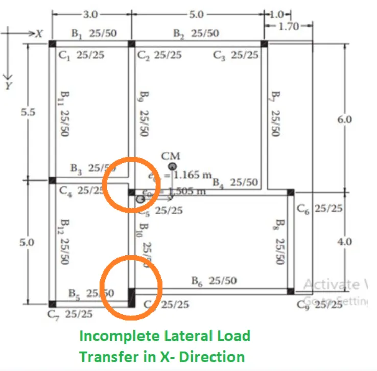
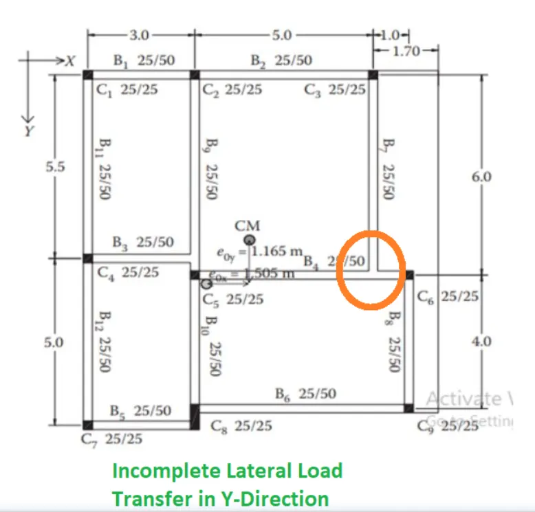
- Lateral Load Transfer in X and Y directions
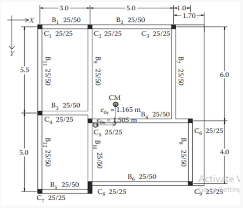
In the figure, we can see in the marked circle that the beam is placed on the other beam. The load is not directly transferred to the column.
When the Lateral load is applied this type of arrangement is not effective to resist.
During the conditions the primary beam on which the beams are rested is subjected to shear failure.
- Eccentricity
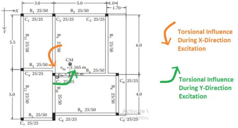
Torsion is created when the centre of mass (CM) and the centre of rigidity or
resistance (CR)
in the building do not coincide.
The distance between these two points is referred to as eccentricity.
CM is usually the geometric centre of the floor (in plan).
If the distance between centre of mass and the centre of the stiffness is longer,
then the torsional moment of the building in both X and Y directions is higher.
- Strong beam Weak Column possibility
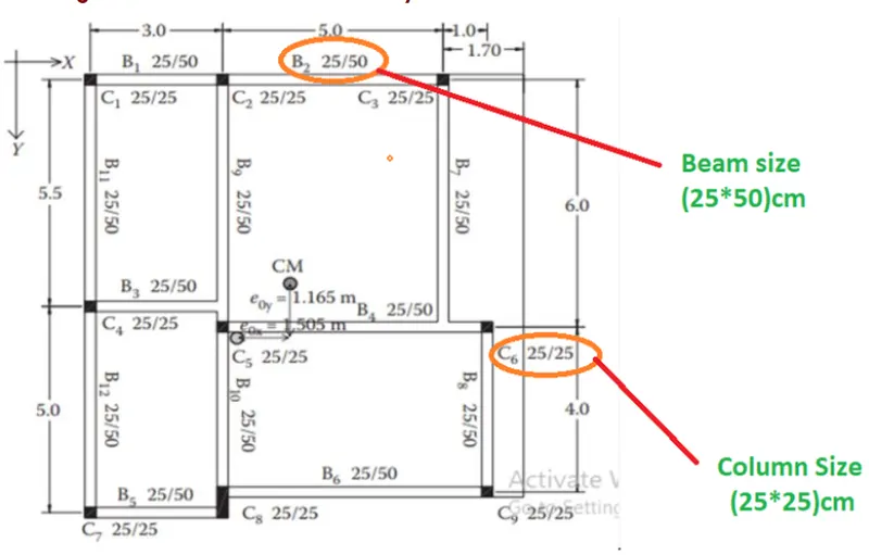
The sizes of the beam are given as 25cm x 50cm.
The sizes of the beam are given as 25cm x 25cm.
The beam is much deeper than the column depth that means inertia of the beam is higher than the column.
The situation is ok if the reinforcement in the column is adequately greater than that of beams.
Since we do not have the reinforcement details, this is doubtful.
It is advisable to have slight bigger size for columns otherwise it leads to soft storey mechanism.
- Translational modes vs Torsional modes
Given that the eccentricity values as ey = 1.165 and ex = 1.505.
Stiff vertical elements are also not symmetrically distributed arround the periphery of the building.
It Could be possible that Torsional mode of vibration could me larger than Translational modes of vibration.
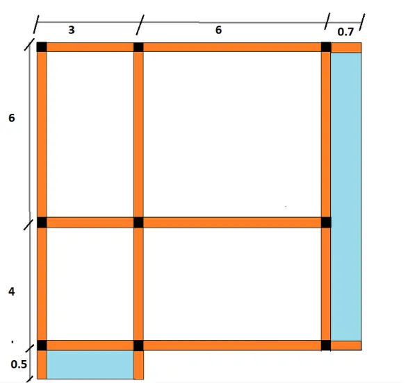
Alternative Scheme:
RESULT: -
We discussed qualitatively about the given plan regarding:
- Torsional flexibility
- Translational modes & Torsional modes
Suggested an alternative plan.
3Q]
AIM: -
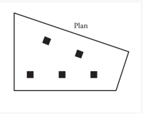
Propose and justify for the choice of the lateral-load-resisting system and its foundation for the given plan.
PROCEDURE: -
Observations in the given Framing plan:
Floor Plan:
According to the General principles of Conceptual Seismic design, the given plan (quadrilateral
plan) is not in uniform, not in symmetric and not even in redundancy.
Probably there will be eccentricity in the plan.
Given plan is very weak in resisting the torsional moments because of this eccentricity.
Even any lateral load applied in the plan will not have 100% influence in the same direction.
So, a special lateral load resisting system has to be provided to resist these torsional moments.
Internal Columns: -
A symmetrically well distributed layout of columns is appropriate to achieve uniformity and the structure becomes more reliable to resist the earthquake effects.
In the given plan the internal columns are placed randomly.
These columns can not transfer lateral forces efficiently and the structure is not at all reliable to resist the earthquake effects.
So, we have to design these columns by assuming the functional design og these columns is only for gravity loads.
Floor to Floor variations
The functional use of beam in the structure is for shear transfer from floor to column.
The partition walls in the structure provides mass distribution and mass control.
As the plan is in Quadrilateral shape all these elements are not in an order.
So, there will be no uniform distribution of lateral load and heavy distortion and distribution of lateral loads will happen.
SUGGESTIONS
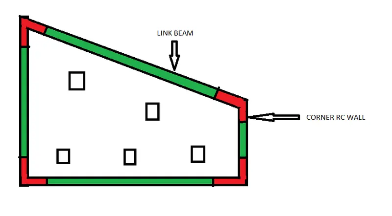
- Heavy Torsional forces created by random location of columns and eccentricity has to be controlled by specific lateral load system. Corner Shear walls should be adopted.
- From the plan, the Left side is greater than the right side. So, the Floor area is greater on the left side than on the right side.As the Floor area on the left side is greater, so the mass of the structure is greater on the left side.Hence the corner shear walls should be heavier on the left side.
- Link beams are used to connect these shear walls and to transfer load from one to the other.
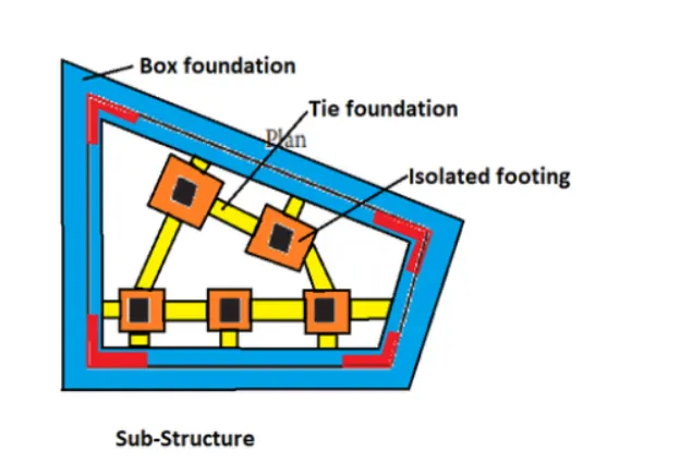
- Box foundation should preferably be used.
- Provide Isolated Footing to support the columns. Connect these footings with shear walls using Tie beams.
PROPOSED SCHEMATIC PLAN:
1) Super Structure
2) Sub Structure.
RESULT: -
We proposed and provided justification for the choice of the lateral-load-resisting system and its foundation for the given plan.