Conceptual design of a building with columns and shear walls
1) Answer
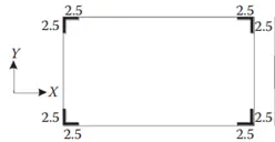
ARRANGEMENT(a)
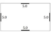
ARRANGEMENT(b)
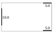
ARRANGEMENT(c)
(i) Restraint of floor shrinkage:
(a) Arrangement a:
- As we can see from the given image,we can see there are 4 shear walls which are provided at the corners of the wall.
- So because of the positioning of the shear wall which is placed at the edges of each wall,it means that they offer strong resistance to the floor shrinkage.
- Which means that the floor will be tightly held at the place because of the shear walls that are positioned at the corner.
- And the shrinkage will be controlled.
(b) Arrangement b:
- As we can see at the above given image, the shear walls are positioned at the centre of the wall on all the four sides.
- Which means that it has better stability to floors that are near to the floors.
- But the shrinkage can occur at the corner of the walls,because at the corners there are no shear wall placed as we can see at the above given image.
(c) Arrangement c:
- As we can see at the above given image,the shear wall that can be seen in the above image are not symmetrically arranged. It is arranged assymmetrically along the given walls.
- And it is not in a complete shape as we can see at the above image.
- So the shear walls are positioned assymetrically and arranged in an orderless manner,we can say that there is high chances of shrinkage of the floor.
- Here in one side the floor shrinkage at corner can be solved but in the other side the shear wall is in the centre so we can't overcome the floor shrinkage.
CONCLUSION:
- After the above discussion we can conclude that arrangement a will have higher restraint to the shrinkage which may leads to the cracks in the floor.
- Arrangement b is considered to be an average option.
- But the arrangement c is not restraint to the shrinkage which means it may not cause craks to the floor.
(ii) The Lateral Stiffness:
(a) Arrangement a:
- As we can see at the above given image,the shear walls are positioned only at the corners of the walls.
- So when there is a possibility of earthquake,the seismic forces will tends to acts along the edges of the floors.
- Which means that the walls where the shear walls are positioned at the corners of the walls only,will have low lateral stiffness and have low stability also.
(b) Arrangement b:
- As we can see at the above given image,the shear walls positioned along the edges will have better stability and have better lateral stiffness along both the principal planes i.e, X-Y directions, and this is because of the positioning of the shear walls.
(c) Arrangement c:
- As we can see at the above given image,there are two shear walls in the X-direction but there is only one shear wall in the Y-direction.
- Which means that this shear wall will increase the lateral stiffness in the X-direction.
- And the shear wall in the Y-direction,it will only concentrate earthquake forces in that wall where there is only one shear wall i.e, in the Y-direction.
CONCLUSION:
- After the above discussion we can conclude that the arrangement b will provide high lateral stiffness other than the arrangement a and arrangement c.
(iii) Vertical Reinforcement at the base:
(a) Arrangement a:
- As we can see at the above given image, these shear walls are positioned at the corners of the walls.
- So because of the positioning of shear walls,there are very little role of the lateral force resistance.
- Which means these walls will not required huge amount of reinforcement, less reinforcement is required.
(b) Arrangement b:
- As we can see in the above image the shear walls are positioned along the main directions.
- Which means they absorb a good amount of lateral forces.
- Because of this, more reinforcement should be added to these walls in order to withstand the lateral forces.
(c) Arrangement c:
- As we can see at the above given image,we can say that the shear walls are not in symmetric order. They are asymmetrically arranged in the above given image.
- So it means these shear walls will take up some or significant amount of lateral forces.
- We can see that the left side of the room will take up a significant amount of lateral forces.
- Therefore, these walls must be heavily reinforced in order to prevent the significant amount of lateral forces.
CONCLUSION:
- After the above discussion we can conclude that the arrangement c will require high vertical reinforcement.
- Arrangement b will require the least reinforcement than the arrangement c.
(iv) Static eccentricity:
(a) Arrangement a:
- As we can see at the above given image there is no eccentricity because the positioning of the shear walls.
- As the shear walls are positioned at the corner of the walls and they are symmetric in nature it means there is no eccentricity.
- But the center of mass end the stiffness both of them coincides in this above given plan.
(b) Arrangement b:
- As we can see at the above given image there is no eccentricity because the positioning of the shear walls.
- As the shear walls are positioned at the corner of the walls and they are symmetric in nature it means there is no eccentricity.
- But the center of mass end the stiffness both of them coincides in this above given plan.
(c) Arrangement c:
- As we can see at the above giving image,there will be an eccentricity in the arrangement.
- Because as we can see that the positioning of the shear wall at the left side of the plan or layout,there is only one shear wall along that side with a larger mass as compared to the other two walls in the Y-direction.
- As a result the centre of stiffness will shift towards the left side of the shear wall.
CONCLUSION:
- After the above discussion we can conclude that the arrangement c will have higher static eccentricity other the arrangement a and arrangement b.
(v) Foundation system:
(a) Arrangement a:
- As we can see at the above given image,the shear walls are placed at the corner of the walls.
- Therefore, we can provide an isolated footing with a tie beam which can be used as a foundation.
(b) Arrangement b:
- Here the walls are provided in the middle or centre of building in both direction.
- In this layout we can use a raft foundation or box foundation.
(c) Arrangement c:
- As we can see at the above given image, we can conclude that this type of layout will have strip footing.
- It is best if we provide this strip footing for the walls in the X-direction and an isolated footing or a combined footing in the Y-direction walls.
CONCLUSION:
- After the above discussion arrangement a and arrangement c should be provided with isolated and strip footing.
- And arrangement b is recommended to have a box foundation.
(vi) Architectural constraints:
(a) Arrangement a:
- As we can see at the above given image, the walls are symmetrically arranged end arrange in an order. Therefore these walls blends well with the architectural design.
- These walls does not cause any clashes with any architectural components because they are arranged in a very systematic manner.
(b) Arrangement b:
- As we can see at the above given image, we can say that these walls are not in symmetric manner or we can say that these walls are irregularly arranged so because of this,these walls may clash with the other architectural components as opening.
- Because we knew that any openings in these walls are not advisable.
(c) Arrangement c:
- As we can see at the above given image, that there are two walls at the right side. In these two walls blends well with the other architectural components.
- As we can see that there there is only one wall at the left side in the Y-directions so these walls may clash with the architectural design.
CONCLUSION:
- After the above discussion we can conclude that the arrangement a is the most preferrable one other than the arrangement b and c.
- But we can say that the arrangement c cannot be accepted either architecturally nor commercially.
(vii) System's redundancy:
(a) Arrangement a:
- As we can see at the above given image,the shear walls that are positioned at the corner of the walls does not take large amount of lateral force,so because of this the other parts of this plan needs to take the good amount of lateral force.
- That's why we can say that this structure is less redundant.
(b) Arrangement b:
- As we can see at the above given image, the shear walls are arranged at the mid-portion of the walls, this means they experience the forces in equal amount in both the direction.
- So that is why this structure is less redundant.
(c) Arrangement c:
- As we can see at the above given image. The shear walls are positioned asymmetrically in the Y-direction, which means Y-direction will leads to concentrate large amount of loads at the left side of the layout.
- So because of this layout it has poor redundancy because of the asymmetrical arrangement of the shear walls in the Y- direction.
CONCLUSION:
- After the above discussion we can conclude that arrangement a and arrangement b are the most redundant than the arrangement c.
(viii)Tortional Stiffness with respect to vertical axis:
(a) Arrangement a:
- It is clear that all the walls are placed symetrically in all the four corners of the layout.
- There is no chance of creating eccentricity as the centre of mass and centre of stiffness coincides.
- This is a case of torsionally stiff model.Hence less vulnerable to torsion.
(b) Arrangement b:
- This arrangement is also a case of symmetrically placed wall systems at all the four edges of the floor.
- There is no chance of creating eccentricity as the centre of mass and centre of stiffness coincides.
- This is a case of torsionally stiff model.Hence less vulnerable to torsion.
(c) Arrangement c:
- Assymetrically placed shear wall system will leads to create eccentricity as the centre of mass and centre of stiffness do not coincide eachother.
- There is 2 shear walls are placed in the X direction and only one wall is placed in the Y direction.
- This wiill lead to the create more torsion during earthqauke.
CONCLUSION:
- After the above discussion we can conclude that arrangement b is the most redundant and arrangement a is in the medium redundant of Tortional Stiffness with respect to vertical axis, But the arrangement c is the worst and cannot be accepted.
2) Answer
OBSERVATION:-
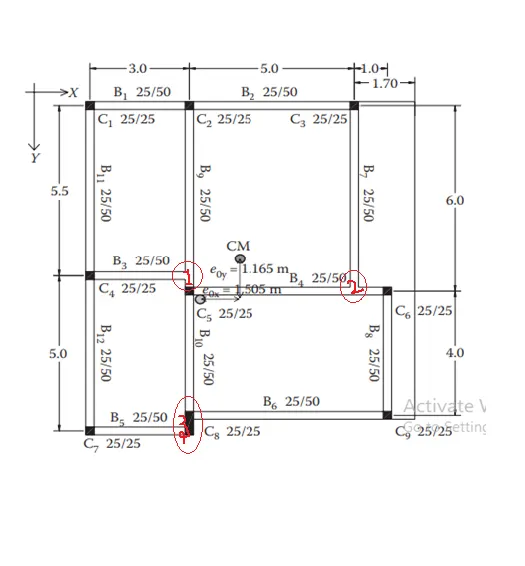
- Beam element B3 has been attached to only one vertical member at left end.
- Beam element B6 has been attached to only one vertical member at right end.
- Beam element B7 has been attached to only one vertical member at the top.
- Hence there is complexity in load transfer at these 3 positions.
- The columns and beams are not placed in grid positions infact they are offseted from their path due to which load does not transfer effectively.
- Proper symmetry is not achieved.
- Beams are found to be stronger than the column elements will leads to the weak column strong beam condition.
ALTERNATIVE:
- Rearrange the columns in such a way that each horizontal members are supported with two vertical members at both ends.
- All the beams and columns should be placed in the form of grid pattern.
- Providing shear walls at suitable places provide better resistance in taking lateral forces.
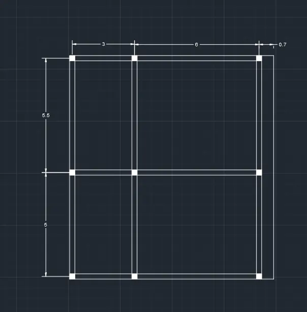
(ALTERNATIVE PLAN)
Torsional flexibility:
- Here in the structural frame has a two way eccentrecity with the centre of mass in relation to the centre of stiffness, with the eccentricity of the X direction is greater than the eccentricity of Y direction.
- Hence the centre of mass does not coincide with the centre of stiffness leads to the experiance toryion in the vertical axis.
3) Answer
Observations:
Here are the few observations that have been made after analysing the above given plan. So below here are the some observations which are made after analyzing the above given plan:
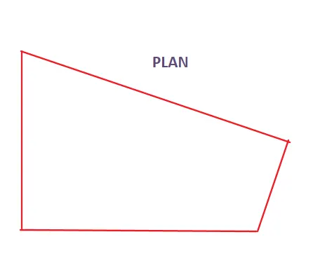
- First of all this layout is not at all suitable for the earthquake prone areas due to its uneven symmetry. This type of plan is not at all adviseable for the earthquake prone areas
-
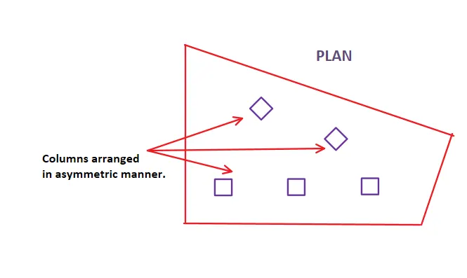
- Columns and the beams are not placed as per the grid patterns.
- So we can say that the centre of mass lies towars the left side of the plan because as we can see that the area at the left hand side of the layout is bigger that the area of the right hand side as we can see at the below given image:
-
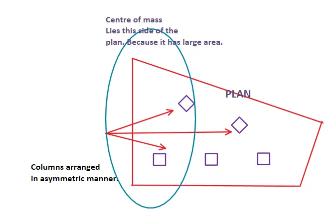
- So as we can see that the given above layout is not at all suitable for the earthquake prone area because of its asymmetrical shape. It is quadrilateral in shaped and this shape is not suitable for the earthquake prone areas. And because of this asymmetric shape the centre of mass of the building is towards the left side of the layout because this side has larger space that the right side of the layout.
- So to shift the centre of stiffness little bit towards the centre of the mass of the system we need to provide the lateral resisting system in order to avoid the torsional irregularities.
- And we must provide L shaped shear wall at the each corner of the layout to obtain the bi-directional strength of the frame.
- We can also provide the tie beams and the box foundation in the above given plan.
- By providing the shear walls at the edges of the walls we can also reduce the torsional rigidity.
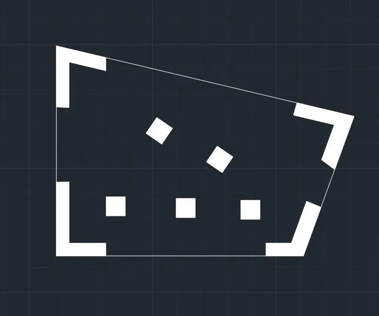
Note: The above drawing is just a imaginary drawing and not up to scale. It is just drawn for reference.