Concept on positioning of Columns
Question 1:
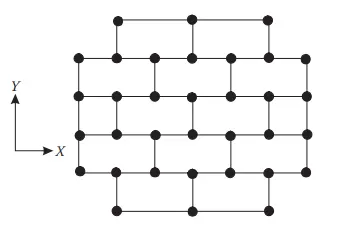
Comment on the layout of the framing plan concerning earthquake resistance in the two horizontal directions X or Y (dots are columns, lines depict beams). Look into aspects of symmetry, redundancy, and bi-directional stiffness and ductility.
ANSWER:
- Aspect of Symmetry
When we observe the plan view given in the question, we can clearly see that the structural configuration is mirrored in both of the cartesian directions. Hence we can conclude that the structural plan given in the question is completely symmetrical in both X-Y planes and is capable of even distribution of stresses.
- Aspect of Redundancy
Structural redundancy can be defined as the amount of extra strength provided in the moment-resisting frame than what is required for that particular design. Thus, the more redundant the structure will be, the more it will be able to resist the loads in case of overstressing. So, the aspect of redundancy for the given frame is inspected in X and Y directions as follows:
- X-direction
When we look at the given plan in X-direction, we can see that the number of columns provided is more and at the same time, all columns are equispaced. Thus, this placement of more columns in proper coordination with each other will surely increase the redundancy of the structure in the X-direction.
2. Y-direction
In comparison with the X-direction, we can observe that the Y-direction has less numbers of columns. However, the alignment of the column is well divided in the Y-direction as well. Hence, we can conclude that the Y-direction also has sufficient redundancy but it is less than that of the X-direction.
- Aspect of Bi-directional Stiffness
1. East-West
We can see clearly that columns in the X-direction are continuously connected making a complete path for efficient load transfer. The frame design in the X-direction does not possess any gaps in-between. As a result, the applied load will not be diverted in this direction. Hence, we can say that there is sufficient bi-directional stiffness present in the structure concercing the East-West directions.
2. North-South
When you look closely into the Y-axis of the given moment-resisting frame, you can observe that the columns are not connected with each other via beams. As a result, there are more than three isolated frames formed in this direction. This will lead to improper load transfer as the connection is not complete. For example, if the load is applied from the bottom portion in the Y-direction, it can only go up to the adjacent beam and then it will be diverted in the X-direction leading to a flawed load transfer mechanism. Hence, we can conclude that the bi-directional stiffness in the North-South directions is not sufficient and needs to be improved with proper frame connections.
- Aspect of Ductility
As we know that the ductility is inversely proportional to the stiffness of the structure. Therefore, the more the stiffness of the members, the less ductility of the frame. Thus, the given moment resisting frame is analyzed based on the above rule in both the directions as follows:
1. X-direction
In the X-direction, you can observe that the number of columns present is more than the same in Y-direction. And due to the more number of columns, the frame will be stiffer in this direction. Therefore, based on the rule stated above, the ductility will be less in the X-direction for the given frame.
2. Y-direction
The number of columns present in the Y-direction is less than that of the X-direction. However, there is a sufficient number of columns to resist the deformation. Hence, we can say that the frame is stiff in the Y-direction but not more than X. Therefore, ductility in the Y-direction will be more than that of X.
Question 2:
What are the possible sources of irregularity in the building shown here? Explain how, as an engineer, each of these irregularities should be dealt with.

ANSWER:
1. Irregularity in Elevation:
When you look at the building, it can be clearly seen that the floor area keeps decreasing as we go to the upper floors. Therefore, the elevation of the said building can be labeled as irregular.
How to deal with this irregularity?
To counter this irregularity, we can refer to the IS-1893 TABLE 6 which discusses the limitations on permissible irregularity in the elevation of any building. Thus we can check if the given building satisfies the guidelines given in the table for the elevation.
2. Irregularity in Stiffness: (Soft Story)
As seen in the picture, one of the floors of the building is kept open without any infill walls. This will lead to plastic hinge formation on that particular floor which will, in turn, reduce the stiffness of that story. As a result, the story may fail due to the soft story mechanism during an earthquake.
How to deal with this irregularity?
To check with the irregularity in stiffness, we can again refer to the IS-1893: 2016. Figure 4A of the code deals with detailed design considerations to eliminate the infill walls from one of the building stories. If all of the design considerations are met for this story, no need to change but the design will have to be readjusted as per the code recommendations if it doesn't meet the suitable requirements.
3. Slopy Base:
As observed from the picture, the building is constructed on slopy ground with a significant steep value. Hence this can be considered as an irregularity in the ground base upon which the building is constructed.
How to deal with this irregularity?
The significant difference in the slope will lead to a sizeable variation in the stiffness of different floor levels based on their elevation. So, to counter this problem, we can check with the IS-1893: 2016 FIGURE 5E. This part of the code explains the steps an engineer is supposed to make in order to keep the building stable when constructed on sloping ground.
Question 3:
A 4-story hotel building has an open ground floor for the restaurant. Story 2 to 4 have one row of rooms along each long side in the plan, separated by a corridor. The two short sides of the perimeter are fully in-filled in all storeys, except for certain openings at the ends of the corridor at storeys 2 to 4 and along the right-hand side of the ground floor. There is a staircase near the upper left-hand corner, with straight flights between landings at floor levels and in-between floors. Cross-section dimensions are written next to the member no. in meters.
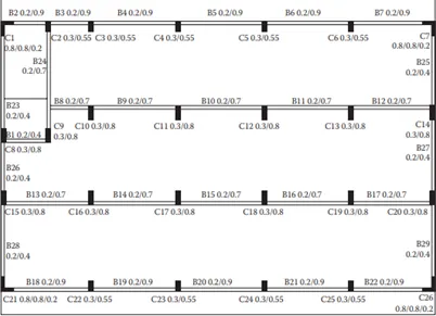
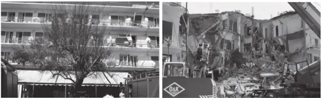
Comment on the features of the structural design and of the layout of infills which are important for earthquake resistance and seismic performance. How do they relate to the almost full collapse of this building (the extreme left-hand bay with the staircase survived, as well as one long-side façade in the rear end, and the frame along the right-hand side in plan).
ANSWER:
Primary Reasons for the Collapse
- Soft Story Mechanism
As mentioned in the question, the ground floor of the building had been left open for the restaurant. This must-have resulted in the soft story formation at the ground level. And during the earthquake, the ground floor was less stiff compared with the upper floors and hence the collapse happened.
- Improper Mass Distribution Along the Building Height
In the plan view, there are three sections divided longitudinally. And out of these three sections, the central portion has been left for the corridor. As a result, the mass distribution of the building becomes irregular. Two portions with rooms have higher masses compared to the corridor region.
- Unbalanced Infill-walls Provision
As mentioned in the question, the infill walls are only placed along the shorter axis of the building plan. This results in imbalanced stiffness over the longer plan axis. This is also one of the reasons for such a massive collapse of the structure.
- Staircase Provision
AS we know that the staircase and lift pit are constructed with concrete. Therefore, these portions are typically stiffer than the masonry work executed for the brick walls. Hence, these structural elements need to be designed at strategic locations to increase the overall structural integrity of the building. And we can also see in the case of the given building that the staircase portion of the building has survived the reason for which has already been mentioned above.
- Improper Structural Framing
As can be seen clearly in the plan, there are no beams provided in the Y-direction to connect all the columns. This leads to improper load distribution along the Y-Axis. Due to this, the North-South direction faces overstressing which can be counted as one of the reasons why the building failed miserably.
- Disproportionate Columns Orientation
It is clearly observable from the plan that column length in the Y-direction is way more than that in the X-direction. This disproportion leads to mismanagement of the structural stiffness and stress distribution. Thus it is also one of the reasons for the fall down.
- Varying Column Dimensions
Columns placed on the interior side of the structure are larger in size as compared to the columns placed along the periphery of the building. The obvious reason behind this is the larger mass present inside the structure. However, the sizes of the varying columns also cause the lateral drift of the columns and thus the collapse.