Concept on positioning of Columns
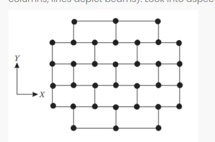
Ans 1: Layout discussion on the basis of Symmetry, Redundancy, Bidirectional Stiffness & Ductility of the Frame here alongwith as follows;
1. on Basis of Symmetry: 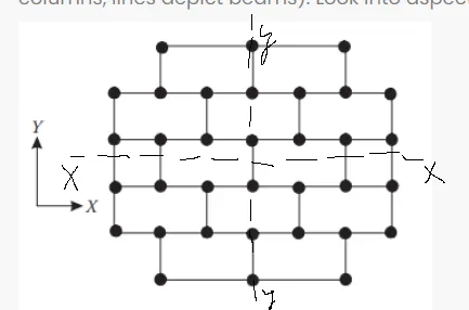
Layout Plan is symmetrical in both the axis.
2. Redundancy:
Columns along the X axis are more in No. hence, They are providing more lateral stiffness to the Overall building than Columns along the Y axis except at the two extreme ends where Redundacy is less.
Layout along the X- direction are more redundant than along Y- direction.
3. Bi-Directional Stiffness: As mentioned Above, Columns along X axis are more in no. and all the column are well connected with Floor Beams along the Shortest possible path for transfer of Seismic X forces while Columns in Y Direction are almost equal in no. but there is discontinity in beams for transfering the Lateral Forces from one end of the Frame to another.
so, Layout plan is more stiffer in X direction than along y- direction.
4. Ductility:
Ductility is inversely Proportional to stiffness so, from here we can annotate that:
Layout is more ductile in Y direction than along X- axis.
===============================================================================
Ans 2: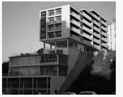
Possible Source of Irregularities in above attached Photo:
1. Discontinity of Columns along the Height of the Building: The Lateral Force Resisting System should be continuous from the base of the Storey to the top of the Building.
Observation: Vertical Columns along the 3rd & 4 th Storey can not be Visible in first two Storey.
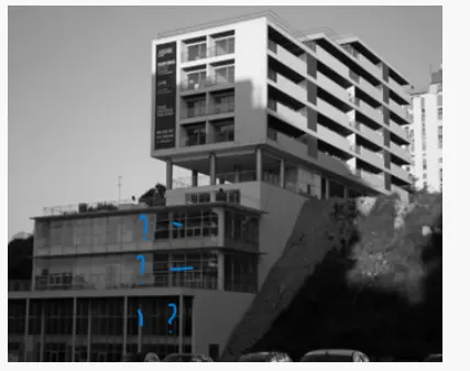
2. Mass irregularity: Mass non-Uniformly distributed along the height of the building, its more on the Upper stories above the soil slope.
3. Stiffness Irregularity: there is a soft storey at the 5th floor of the building above the soil slope on Right side of the building.
4. Vertical Geometric Irregularity: Limitations on Horizontal setbacks/ Offsets in Horizontal direction along the elevation must be checked out which is limited to only 12.5% of the base dimensions of the storey under it.(Table 6 ponit 3rd of Is 1893:2016)
5. In-Plane Discontinity in Vertical Elements Resisting Lateral Force:
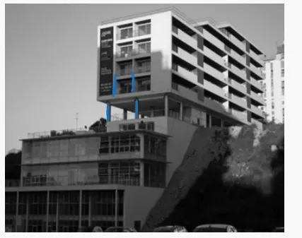
this offset can be limited to 20% of Plan length of these elements, only for Seismic Zone 2 consideration. For Higher Seismic Region i.e., 3, 4 & 5 th Region, Inplane Discontinity in vertical elements should be strictly prohibited.
All the above Irregularities corresponds to Vertical Deformity.
Hereunder comes the Plan irregularities:
1. Torsional Irregularity: Due to Soil slope on one side of the Building, Stiffness of the Right Hand Side is increased continuously while the other side of the building doesnot have that much stiffness along its height. So There are more chances of this building to get tilited to Inplane deformation or Torsional Irregularity.
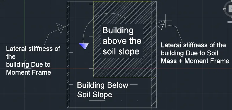
2. Re-entrant Corner:
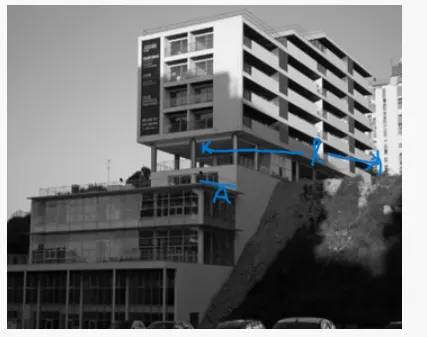
As per Table 5 of 1893:2016 point (b), A/l should be less than 15%.
3. Non- parallel Lateral Force System:
===================================================================================
Ans 3: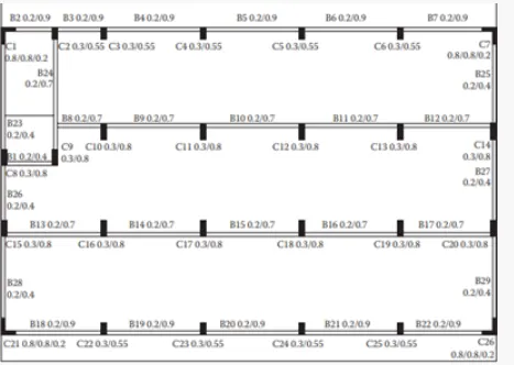

1. Stiffness Irregularity: As mentioned above, the two Lateral side walls are provided along the short direction with few openings at the corners, shows that Lateral sides of the Building has enough restraint to bear the lateral forces while the opening at the Ground Floor sacrifices Stiffness in the Front Portion of the Building.
2. Mass Irregularity in plan: As shown in Layout plan, Two long sides of the plan are occupied by the rooms from
2nd to 4 th Floor which means Mass is concentrated on two edges of the property line with no significant mass at the middle portion in the Corridor.
3. Weak Storey: Restaurant at the Ground Floor diminishes the stiffness of the Vertical members reducing its lateral load resisting capacity. Open Storey at the Ground Floor with special Bracing results out in lesser stiffness of the frame members.
4. Staircase portion at the top left side in the Layout plan provides greater in strength & stiffness. Portion does not get affected by the EQ.
5. Force Transfer along the Y axis through Floor beam are not provided in Layout plan, which is the most Stingent drawback behind this Failure.
6. 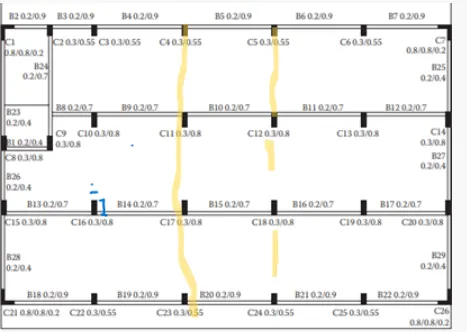
6. Beams moving along the X axis are supported on columns with less bearing/ support resulting in less stiffness in X direction while Longer dimension does not have any beam but still it is provided with longer Direction.
it means Column Configuration should be reiterated once again.
7. Variation In column Sizes:
inner Columns are larger in dimensions than outer perphiery columns, it is usual to provide larger column on inner side but by Doing this, this lead to significant difference in Lateral drift of Columns.
some members may reach to Inelastic Deformation (Outer Column) while Inner Column remain in Elastic state, resulting in Torsional Flexibity of the plan or we can manifest to be Out of plane Deformation.