Concept on positioning of Columns
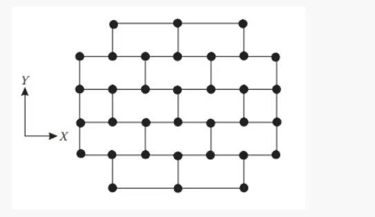
Q.1 COMMENT ON THE LAYOUT OF THE FRAMING PLAN CONCERNING EARTHQUAKE RESISTANCE IN THE TWO HORIZONTAL DIRECTION X OR Y (DOT ARE COLUMN LINES DEPICT BEAM) LOOK INTO ASPECTS OF SYMMETRY REDUNDANCY AND BI-DIRECTIONAL STIFFNESS AND DUCTILITY.
ANS:
- Investigation of the framing plan with respect to symmetry: if we split the plan vertically half it will look mirrored. So we conclude the given plan is symmetric in x-direction. If we split the plan horizontally half it will look mirrored so we conclude the given plan is symmetric in y-direction
- Investigation of the framing plan with respect to redundancy: the columns in x-direction are comparatively more and evenly spaced so the structure is more redundant in x-direction. Except the top and bottom column row are having quite longer spans. The columns in y-direction are comparatively lesser but evenly spaced so the structure is redundant but lesser than that of in x-direction
- Investigation with respect to bi-directional stiffness: the column in horizontal direction are connected with straight beams. This mean any lateral load (seismic force In x-direction) passing from left end of the building will have its path straight till it reaches right end of the building. So no or less possibility of force diversion take place. The column in vertical direction are not connected with straight to straight beams. So a lateral load passing from south side of building will get diverted to east & west direction to reach next bay. There will be major force diversion take place with seismic force in y-direction. The framing plan is weak with respect to bi-direction stiffness in y-direction. The framing plan is weak with respect to bi-directional stiffness in y-direction
- Investigation of the framing plan with respect to ductility: prima facie, the aspect ratio of the plan clearly hint more column in x-direction compared to y-direction. It will result in higher stiffness of the building in x-direction which would reduce ductility in x-axis. Moreover the x-force will easily pass from one bay to its next due to beam alignment. Whereas the y-force will struggle to pass through. The north south beam are arranged om zig-zag which leads to a discontinuous bracing
Q.2 WHAT ARE THE POSSIBLE SOURCES OF IRREGULARITY IN THE BUILDING SHOWN HERE? EXPLAIN HOW AS AN ENGINEER, EACH OF THESE IRREGULARTIES SHOULD BE DEALT WITH.
ANS:
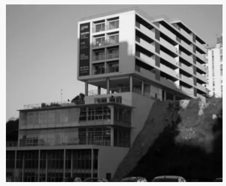
- Vertical irregularity – the building plan area large in bottom stories. The floor plan areas are getting reduced with increase in height. These building offsets has to be crossed checked with reference to IS-1893-2016 table-6 serial number (iii)
- Soft story – the building has uncovered opening space in 6th
floor. As there is no occupancy or a partitional wall, this will lead to plastic hinge formation at the column (with reference to IS-1893-2016 FIGURE 4A) this has to be checked and sufficiently designed
- Slopy base – the building is constructed on a sloping ground at one side this will lead to significant variation in the stiffness (with reference to IS-1893-2016 figure SE) few levels may be subjected to soft storey mechanism.
Q.3
ANS:
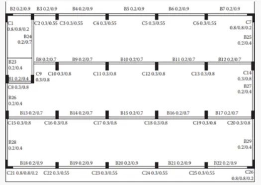

- Open ground floor – this denotes softs storey mechanism acting in the building
- Room along 2 bays separated by an open corridor – the bays filled with rooms will have higher mass compared to the middle bay left open for corridor. This induces mass irregularity along height uniformly
- Two short sides covered with infill walls – this means the building left and right sides periphery is more stiffer during seismic forces (especially along north-south)
- Staircase portion at left top corner – usually staircase and lift portion are stiffer than other parts because of concentrated concrete elements. So the staircase portion contains more stiffness in the provided building plan
- No framing connection along y-direction- we could see no structural beam provided along the vertical direction between column. This makes the building more vulnerable during the north-south seismic force
- Beams connected along column minor axes – the column are having longer dimension in y-direction. This means they are stiffer along y-direction. But the beams are running only along x-direction which would attract much lesser lateral forces and hardly transfers it
- Variation in column size – the internal columns are having higher sizes compared to exterior (this is common because of higher load demand). But this will lead to significant difference in lateral drift of column. So the concrete floor might have suffered heavy out of plans shear which would led to collapse