Concept on positioning of Columns
Objective :
- To understand the impact of vertical and horizontal members in seismic behaviour of a structure.
- To understand different irregularities in a building.
Ans 1.
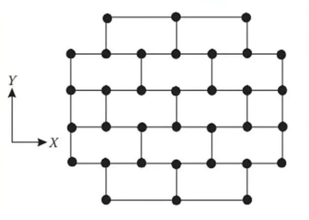
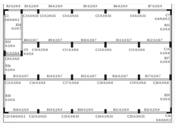
- Investigation of the framing plan with respect to symmetry in X direction.
If we split the plan in half from vertical direction it will look in mirror form so that we can say that the given plan is symmetric in X direction.
2. Investigation of the framing plan with respect to symmetry in Y direction.
If we split the plan in half from horizontal direction it will look in mirror form, so that we can say that the given plan is symmetric in Y direction.
3. Investigation of the framing plan with respect to redundancy in X direction.
The structure is more redundant in as direction because the columns in X direction are comparatively more and evenly places. Only the top and bottom column rows are having longer Spans.
4. Investigation of the framing plan with respect to redundancy in Y direction.
For Y direction we can observe that the structure is redundant but lesser than that of in X direction because the column in Y direction are comparatively lesser but evenly placed.
5. Investigation with respect to bi-directional stiffness.
As we can observe that the columns in horizontal direction are connected with straight beams. So that in X direction the seismic force passing from left hand of the building will have its path straight to the right end of the building and hence no or less possibility of force division takes place.
And here we can observe that the columns in the vertical direction are not connected with straight to straight beams. So in my direction the lateral load coming from the South will get diverted to the east and West direction to reach its next beam. Here you can see that imager force diversion takes place with seismic force in Y direction. The framing plan is weak with respect to bi-directional stiffness in X direction.
6. Investigation with respect to bi-directional ductility.
It is clearly visible in the figure that there are more columns in X direction as compared to Y direction. Because of that there will be higher stiffness in the building in his direction which bit reduce the ductility in X direction.
The north South beams are arranged in a zig zag manner which leads to discontinuity of beams. Therefore the force in the X direction will easily pass from one end to another end of the building whereas the Y direction of force will struggle to pass through.
And finally through this observations we can conclude that the given framing plan is more ductile in Y direction than that of in X direction.
Ans 2.
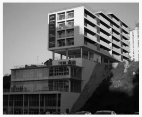
1. Vertical irregularity.
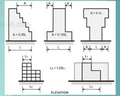
As we can observe that there is large plan area in the bottom stories of the building. With the increase in height the floor plan areas are getting reduced. Through refrence IS-1893-2016 table number 6 serial number 3rd this building offsets has been crosschecked.
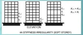
2. Soft Storey.
By observing the figure we can see that at 6th floor the building has uncovered opening space as there is no partition wall or occupancy which results in the formation of plastic hinge at the columns. It has to be checked with reference to IS-1893-2016 figure-4A and design sufficiently.
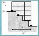
3. Slopy Base.
As shown in the image the building is constructed on a sloping ground at one side. Which results in significant variation in the stiffness of building with reference to IS-1893-2016 figure 5E.
Ans 3.

1. Open ground floor.
The figure shows the indication of soft storey mechanism acting in the building.
2. Room along 2 ways separated by an open corridor.
As compared to the middle Bay which is left open for corridor the bays filled with rooms will have higher mass. This indices mass irregularity along height uniformly.
3. 2 short sides covered with infill walls.
This means that the left and right periphery side of the building is more stiffer during the seismic forces especially along north-South.
4. Staircase portion at left top corner.
Generally the lift and staircase portions are steeper than other parts because the concrete is concentrated element. So the stiffness is more in the staircase portion provided in the building plan.
5. No framing connection along Y direction.
As observed through the image there is no structural beams provided along the vertical direction between the columns which makes the building more vulnerable during the North-South seismic force.
6. Beams connected along column minor axes.
As seen in the image in Y direction the columns are having longer dimension which means they are more stiffer in the Y direction. What the things are running only along X direction which would attract much lesser natural forces in hardly transfers it.
7. Variation in column sizes.
The internal columns are having higher sizes compared to exterior columns this is common because of higher load demands but this will lead to significant difference in lateral drift of columns. So the concrete floor might have suffered heavy out-of-plane shear which would led to collapse.
..........................Thank You.................................................