Concept on positioning of Columns
1Q]
AIM: -
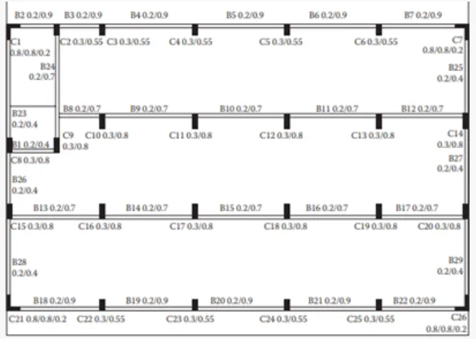
Comment on the layout of the framing plan concerning earthquake resistance in the two horizontal directions.
Look into aspects of symmetry, redundancy and bi-directional stiffness and ductility.
PROCEDURE: -
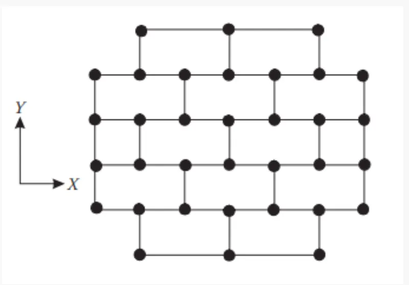
SYMMETRY IN-PLAN: -
To achieve uniformity, a symmetrical, well distributed in-plan layout of structural elemens is appropriate.
We have to maintain symmetry not onnly in plan-wise distribution of stiffness and strength but also in distribution of mass.
We have to avoid eccentricities that entail torsional response, which tends to increase the horizontal displacement in some parts of the periphery of the building plan.This is unfavouraable.
SYMMETRY IN X-DIRECTION: -
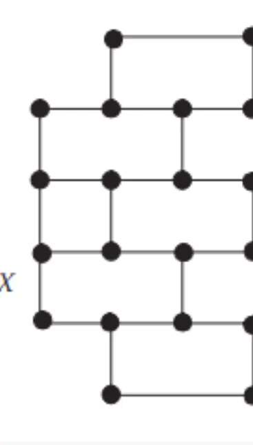
Try to split the plan vertically half.
If they look like mirror image to each other, we can conclude that the given plan is symmetric in X-axis.
In our given plan, we can split vetically half into mirrored image.
So, the given plan is in symmetric in X-axis.
SYMMETRY IN Y-DIRECTION: -
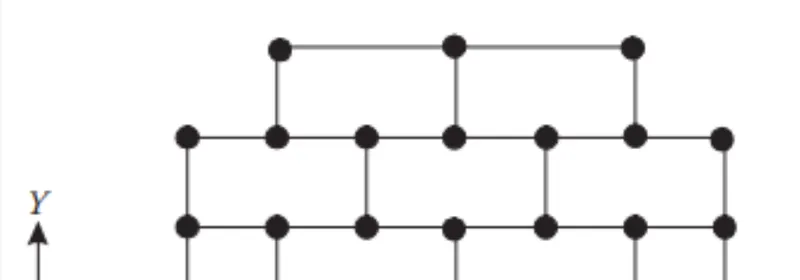
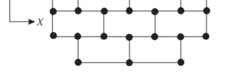
Try to split the plan horizontally half.
If they look like mirror image to each other, we can conclude that the given plan is symmetric in Y-axis.
In our given plan, we can split horizontally half into mirrored image.
So, the given plan is in symmetric in Y-axis.
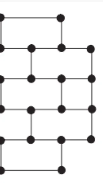
REDUNDANCY: -
The structure becomes more reliable to resist the Earthquake effects by accomodating the loss of some structural elements before becoming unstable.
The redundancy of the structure can be increased by the use of many, evenly distributed structural elements.
Redundancy allows a more favourable distribution of the action effects in the non-linear range and wide spread energy dissipation across the entire structure.
REDUNDANCY IN X-DIRECTION: -
Comparitively columns in X-direction are evenly spaced.
We can say that structure is redundant in X-direction.
But the Top and bottom colum rows are having longer spans.
So, except the top and bottom columns the structure is more redundant in X-direction.
REDUNDANCY IN Y-DIRECTION: -
Columns in Y-direction are evenly spaced.
The Structure is redundant in Y-direction.
But in comparision to X-direction, columns in Y-direction are lesser.
So, the structure in Y-direction is redundant but lesser than that of in X-direction.
BI-DIRECTIONAL STIFFNESS: -
Normally, seismic loads on both horizontal axes of structures are similar, that is why the provision of similar resistant systems in both directions is recommended. So, the structural members need to be configured
orthogonally guaranteeing similar resistance property in both major directions.
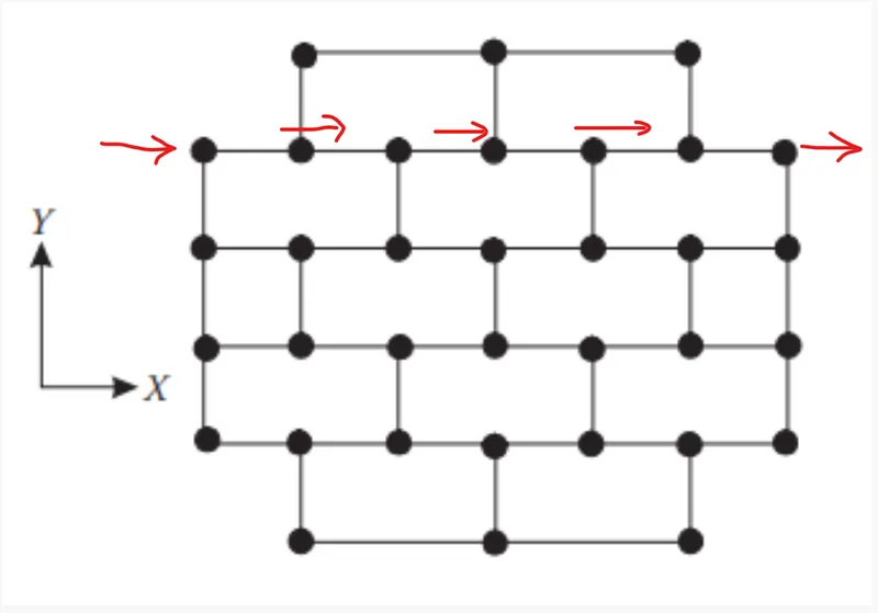
BI-DIRECTIONAL STIFFNES IN X-AXIS: -
A lateral force in X-direction passing from left end reaches right end of the building in a straight path.
This happens because columns in horizontal direction are connected with straight to straight beams.
So, there is less possibility for force diversion.
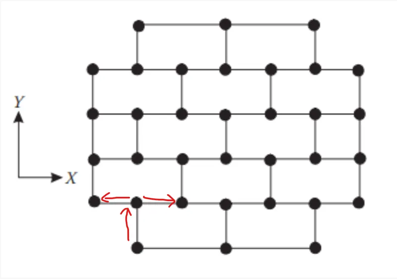
BI-DIRECTIONAL STIFFNES IN Y-AXIS: -
A lateral force in Y-direction or vertical direction passing from south end will split into East and West direction to reach next bay.
This happens because columns in Y-axis or vertical direction are not connected with straight to straight beams.
Force diversion is taking place when seismic force is applied in Y-direction.
Because of this reason the given frame is weak in stiffness in Y-direction compare to X-direction.
DUCTILITY: -
Flexibility is the response (deformation) to a load. Ductility relates to the RANGE of deformation that a material exhibits, not just the direct response to a particular load.
Ductility describes the extent to which a material (or structure) can undergo large deformations without failing.
The term is used in earthquake engineering to designate how well a building will endure large lateral displacements imposed by ground shaking.
Flexibility is the inverse of stiffness.
INVESTIGATION OF THE FRAMING PLAN WITH RESPECT TO DUCTILITY: -
From the given plan we can say that more columns are placed in X-direction compare to columns in Y-direction.
This results to higher stiffness to the building in X-direction.
As we know that, flexibility is the inverse of stiffness, so we have lesser ductility in X-direction.
The North-South direction will have a discontinuous bracing because of Zig-Zag arrangement of beams in North-South direction.
So, the Force in Y-direction will stuggle to pass.
Whereas in X-direction the Force will pass through easily because of the beam’s alignment.
From this we can conclude that given plan has more stiffness and less Ductililty in X-direction and Less stiffness and more Ductililty in Y-direction.
RESULT: -
Concerning earthquake resistance in the two horizontal directions, commented on the layout of the framing plan.
Based on the aspects of symmetry, redundancy and bi-directional stiffness and ductility we deduced conclusions of the given plan.
2Q]
AIM: -
To identify the possible sources of irregularity in the given building.
To explain how, as an engineer, each of these irregularities should be dealt with.
PROCEDURE: -
As per IS 1893 Irregular buildings are mentioned under Table 5 and table 6
Table 5 – Plan Irregularities
Table 6 – Vertical Irregularities
PLAN IRREGULARITIES: -
- Torsional irregularity
- Re-entrant corners
- Floor slabs having excessive cut-outs or opening
- Out-of-plane offsets in vertical elements
- Non-parallel lateral force system
VERTICAL IRREGULARITIES: -
- Stiffness irregularity (Soft storey)
- Mass irregularity
- Vertical geometric irregularity
- In-plane discontinuity in Vertical elements resisting lateral force
- Strength irregularity (Weak storey)
- Floating or stub columns
- Irregular modes of oscillation in two principal plan directions
Let’s analyse the possible sources of irregularity in the given building
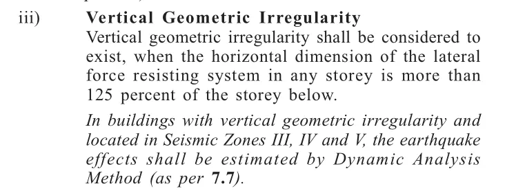
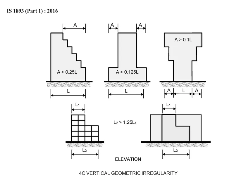
Vertical geometric irregularity
Vertical geometric irregularity shall be considered to exist, when the horizontal dimension of the lateral force resisting system in any storey is more than 125% of the storey below.
From the figure we can see that the floor plan area gets reduced with increase in height.
We have to cross check these floor plans with reference to IS 1893 table 6
Mass irregularity
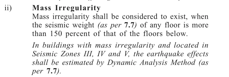
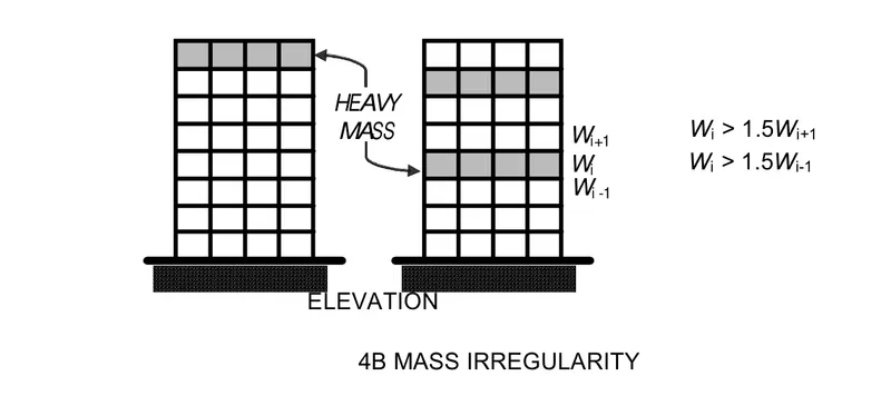
Mass irregularity is considered to exist where the seismic weight of any storey is more than 200 percent of that of its adjacent storey. Mass irregularity is an important factor which affects the response of the structure under seismic loads
From the figure we can see that the floor plan area gets reduced with increase in height.
We have to cross check these floor plans with reference to IS 1893 table 6
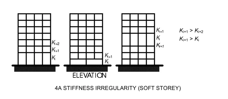
Stiffness irregularity (Soft storey)
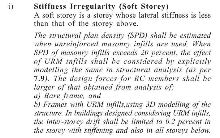
A soft storey is a storey whose lateral stiffness is less than that of the storey above.
From the figure we can see that the 6th floor has open space and not covered with any infill walls or partition walls.
There is a possibility of formation of plastic hinges at the columns.
We have to cross check this with reference to IS 1893 table 6.
Floating or stub columns
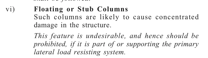
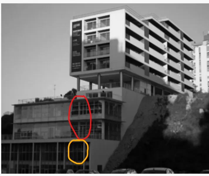
Floating columns are likely to cause concentrated damage in the structure.
In the figure, columns are visible in the 3rd and 4th floor marked with red circle, but columns are missing in the adjacent below floor (2nd and 1st floor) marked with yellow cicle.
We have to re-check with the columns alignment to confirm whether there are any floating columns in the building.
This has to be checked and sufficiently designed.
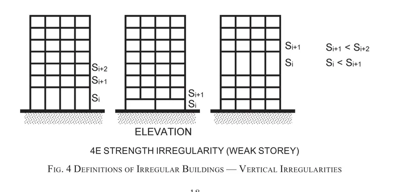
Strength irregularity (Weak storey)
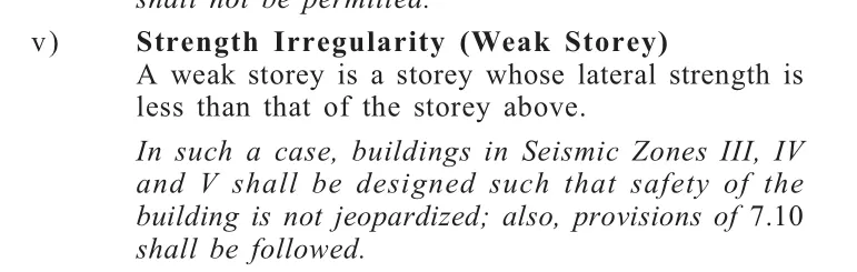
A weak storey is a storey whose lateral strength is less than that of the storey above.
If we compare 6th floor and 7th floor 6th floor has uncovered space and open space which may cause lesser lateral stregth compare to 7th floor.
We have to crosscheck the lateral strength of the 6th floor with other floors and design as per the requirement.
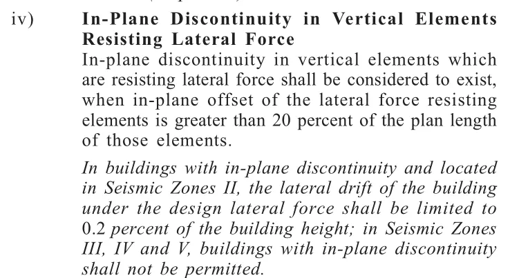
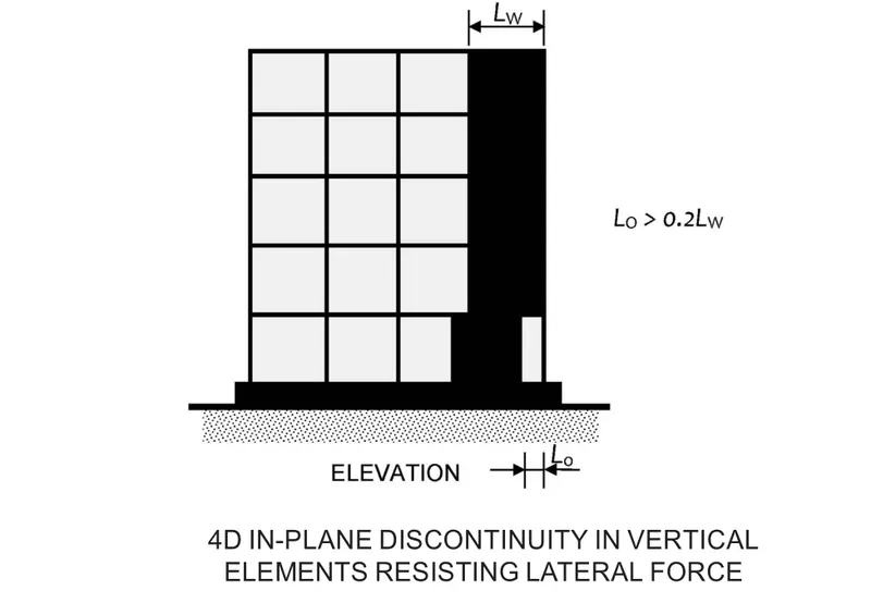
In-plane discontinuity in Vertical elements resisting lateral force
When In-plane offset of the lateral force resisting elements is greater than 20 percent of the plan length of those elements, then In-plance discontinuity in vertical elements which are resisting lateral force shall be considered to exist.
In the given building, there is In-plane discontinuity in between 2nd and 3rd floor and in between 4th and 5th floor.
Lateral force resisting elements are reduced with increase in height.
We have to cross check these floor plans with reference to IS 1893 table 6
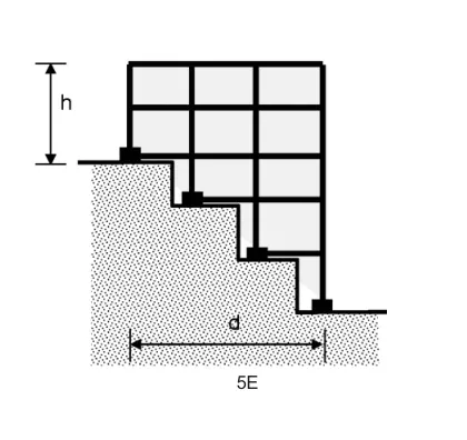
Slopy Base Irregularities
One side of the building is constructed on a slopy base. This will cause significant variations in the stiffness in the building elements.
With reference to IS-1893 table 6, few floors might have subjected to soft storey mechanism.
RESULT: -
Identified the possible sources of irregularity in the building.
As an engineer, explained how each of these irregularities should be dealt with.
3Q]
AIM: -
To comment on the features of the structural design and of the layout of infilles which are important for earthquake resistance and seismic performance.
PROCEDURE: -
From the given question we have to note few observations.
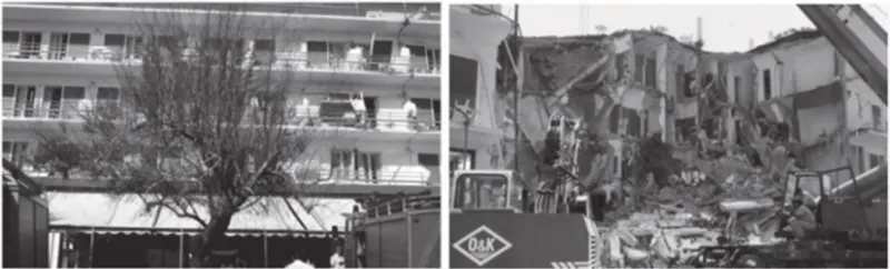
- An open ground floor for the restaurant.
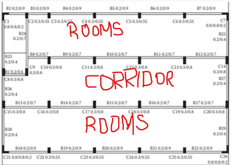
- Story 2 to 4 have one row of rooms along each long side in plan, separated by a corridor.
- The two short sides of the perimeter are fully in-filled in all storeys.
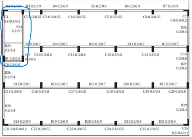
- A staircase near the upper left-hand corner, with straight flights between landings at floor levels and in-between floors.
- No Framing connections along Y-direction.
- Beams connected in the Column shorter direction.
- Difference in Column sizes.
An open ground floor for the restaurant.
Ground floor has uncovered space and open space which may cause lesser lateral stregth compare to above floors.
There is a stiffness irregularity causing Soft storey mechanism.
As per IS 1893 Table 6, a soft storey is a storey whose lateral stiffness is less than that of the storey above.
Story 2 to 4 have one row of rooms along each long side in plan, separated by a corridor.
Rows filled with rooms have higher mass compared to the mass at the middle for the corridor.
Clearly, we can understand that the seismic weight of any storey could be more than 200 percent of that of its adjacent storey.
Mass irregularity is considered to exist where the seismic weight of any storey is more than 200 percent of that of its adjacent storey
Mass irregularity is an important factor which affects the response of the structure under seismic loads.
The two short sides of the perimeter are fully in-filled in all storeys.
Comparatively, the two short sides have more stiffness.
This leads to Stiffness variation in 2 directions.
The Collapse or damage could happen in the weaker stiffness direction.
A staircase near the upper left-hand corner
Comparatively, the staircase and Lift parts have more concentrated concrete elements.
This leads to more stiffness in the staircase and lift parts than other parts in the building.
So, there is a stiffness variation in the left-hand corner and in the other corner of the building.
No Framing connections along Y-direction.
Any lateral force in X-direction passing from left end reaches right end of the building in a straight path because columns in horizontal direction are connected with straight to straight beams.
But, no structural beams are provided along the vertical direction to take up these forces.
This makes the building more detrimental when there is Seismic force in the Y-direction.
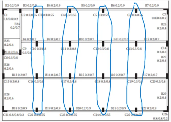
Beams connected to the Column shorter direction.
Columns with longer dimension have more stiffness than with shorter dimension.
In our case, the longer dimension is in Y-direction, that means more stiffness in the Y-direction.
But no framing connections in the Y-direction. Beams are provided only in the X-direction.
Longer dimensions attract more lateral forces but no arrangement to tranfer the forces,
Shorter dimension attracts lesser lateral forces and hardly transfers it.
Difference in Column sizes.
The transfer of seismic forces varies with the column sizes.
Variation in column sizes might have led to significant difference in lateral drift of columns.
The concrete floor might have suffered heavy out of plane shear.
This would have led to collapse of the building.
RESULT: -
Comment on the features of the structural design and of the layout of infills which are important for earthquake has been made with proper justification.