CHARACTERISTICS OF INDUCTION MOTOR & COMPARISON OF INVERTER WAVE
OBJECTIVES:
- Discuss about the equivalent circuit network of induction motor MATLAB model.
- 3 phase, 50 Hz induction motor, represented by equivalent circuit constants X1 = X2 = 0.1 ohm and R1 = R2 = 0.2 ohm is operated at half of rated voltage and frequency. Calculate the ratio of starting torque at half voltage & frequency to rated values.
- Make a comparison of square wave inverter output voltage with sine modulated one.
I. Discuss about the equivalent circuit network of induction motor MATLAB model.
INTRODUCTION:
 >
>
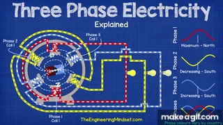
The three-phase induction motor operates in same ways like a transformer. In the transformer, AC voltage is applied to the primary, which creates AC flux in the core. That flux links the secondary and induces a voltage of the same frequency, but with a voltararge that depends on the transformer turns ratio.
The three-phase induction motor has voltage applied to the stator that creates a rotating flux wave. As that wave sweeps by the rotor bars, voltages are induced; however, the frequency of the voltage is determined by the slip of the motor. It turns out that the similarity extends to the equivalent circuits of the two devices.
Induction Motor Matlab Model:
Library:
Powertrain Blockset/ Propulsion / Electric Motors
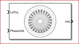
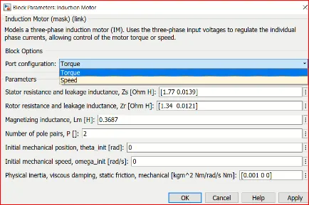
The Induction Motor block implements a three-phase induction motor. The block uses the three-phase input voltages to regulate the individual phase currents, allowing control of the motor torque or speed.
By default, the block sets the Simulation Type parameter to Continuous to use a continuous sample time during simulation. If you want to generate code for fixed-step double- and single-precision targets, considering setting the parameter to Discrete. Then specify a Sample Time, Ts parameter.
Three-Phase Sinusoidal Model Electrical System
The block implements equations that are expressed in a stationary rotor reference (qd) frame. The d-axis aligns with the a-axis. All quantities in the rotor reference frame are referred to the stator.
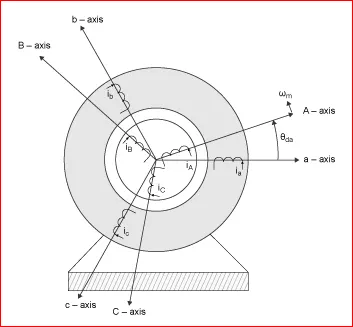
The block uses these equations to calculate the electrical speed (ωem) and slip speed (ωslip).
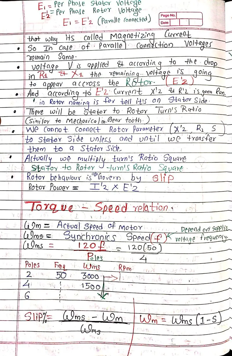
ωem=Pωmωslip= ωsyn−ωem
To calculate the dq rotor electrical speed with respect to the rotor A-axis (dA), the block uses the difference between the stator a-axis (da) speed and slip speed:
ωdA= ωda− ωem
To simplify the equations for the flux, voltage, and current transformations, the block uses a stationary reference frame:
ωda=0ωdA=−ωem
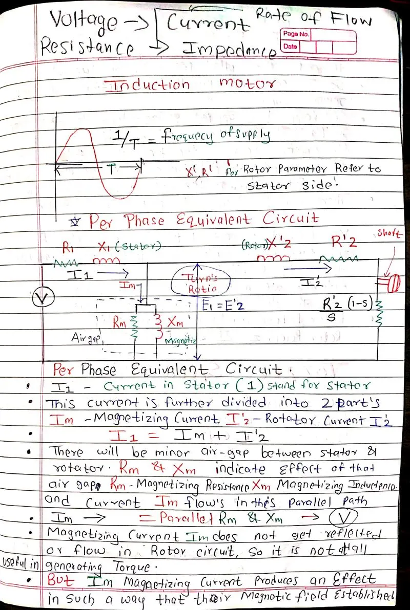
Per Phase Equivalent Circuit:
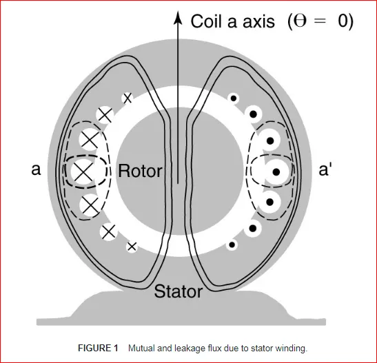
FIGURE 1 Mutual and leakage flux due to stator winding.
Derivation of the Equivalent Circuit of Three-Phase Induction Motor
Figure 1 shows the construction of one phase of the armature winding. When a voltage is applied to the coil, current flows in the winding and flux is established, just as in the transformer. In Figure 1, the mutual flux is indicated by the solid lines passing through the middle of the rotor, while the leakage flux is indicated by dotted lines that do not cross the air-gap.
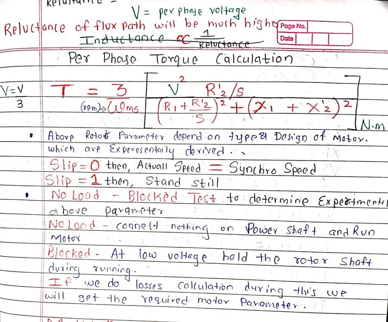
The air-gap in a motor is much larger than that of a transformer, which means that the reluctance of the flux path will be much higher. Inductance, of course, is inversely proportional to the reluctance, so the inductance, and hence the reactance, will be smaller. As a result, the no-load current (or exciting current) will be significantly higher, percentage-wise, for an induction motor. Whereas the exciting current for a transformer is only a few percent of the rated current, the exciting current for an induction motor can be 40% or more of the rated current.
In developing the equivalent circuit for the induction motor, we can recall the equivalent circuit of the transformer. The primary circuit contained inductances to account for the leakage and mutual fluxes and resistances to account for the resistance of the primary winding and the core losses. The stator of the induction motor is essentially the same; there are mutual and leakage fluxes, winding resistance, and core losses due to hysteresis and eddy currents.
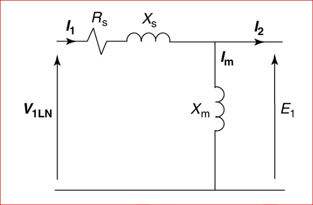
FIGURE 2 Induction motor stator equivalent circuit.
Figure 2 shows the equivalent circuit of one phase of the stator of the induction motor. It is assumed the windings are connected in wye, so the voltage applied to the circuit is a line-to-neutral voltage. The elements Rs and Xs are the stator winding resistance and leakage reactance, and Xm is the magnetizing reactance. This circuit is essentially the same as the primary circuit of a transformer. The only difference is we have not included a core loss resistance. The core losses are often accounted for separately and are thus not represented in the equivalent circuit.
Looking at the stator circuit of Figure 2, I1 is the current entering the winding. As already discussed, a significant current Im, is required to establish the magnetic field. The remaining current, I2, is the load portion of the stator current. The MMF of I2 will exactly cancel the MMF of the rotor current. In phasor notation, we can write,
V1 = E1 + I1(Rs +jXs) ...............(1)
Where E1 is the EMF induced in the stator coil by the mutual flux. We need to add the rotor to the equivalent circuit.
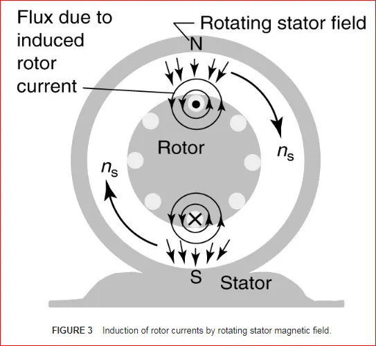
FIGURE 3 Induction of rotor current by rotating stator magnetic field
Looking at Figure 3, as the stator flux sweeps by the rotor conductor, a voltage and current will be induced. If the rotor is not allowed to turn (blocked rotor), then the voltage and current induced in the rotor will have the same frequency as the stator.
We have an unusual form of a transformer, in which the flux rotates around the rotor conductors. In the case of the transformer, we refer quantities from one side to the other using the turn’s ratio. Because most induction motors have squirrel cage rotors, it’s not easy to determine the number of turns on the rotor. Fortunately, we can avoid the problem by always working with quantities referred to the stator.
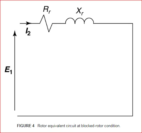
FIGURE 4 Rotor equivalent circuit at Blocked-rotor condition.
Figure 4 shows what’s happening when the rotor is blocked. As the stator field sweeps by the rotor conductors, a blocked rotor voltage, EBR (equal to E1), is induced. Since the coils are shorted, current flows through the resistance and leakage reactance of the rotor coils. In figure 4, Rr is the resistance of one phase of the rotor winding and Xr is the leakage reactance of the rotor when stator frequency currents flow in the rotor, which only happens when the rotor is stationary (slip=1.0). Of course, both Rr and Xr are referred to the stator by an appropriate turns ratio.
For the induction motor to be of use to us, it must turn, which means the slip is less than 1.0. If the rotor is moving, two things happen:
- The relative velocity of the stator field and rotor coil is snsinstead of ns. Recall that E=Blv. Thus, the voltage induced in the rotor will be sE
- Since the frequency of the rotor currents is sfs, the leakage reactance will have a value of sXr.
Replacing E1 by sE1, and Xr by sXr in Figure 4 yields the circuit shown in Figure 5, which is valid at any value of slip. In order to connect the rotor circuit of Figure 5 to the stator circuit of Figure 2, we must account for the different frequencies.
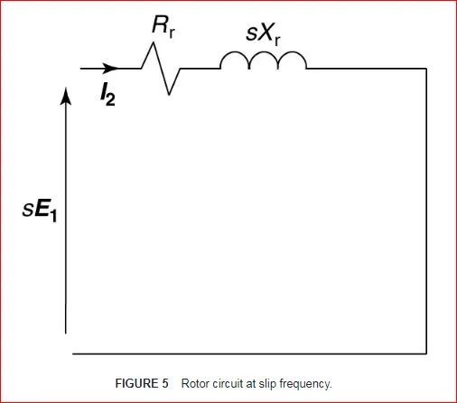
FIGURE 5 Rotor circuit at Slip Frequency
Just as we referred impedances by the turns ratio, we can refer them by the frequency. From the circuit of Figure 5, we can write
sE1 + I2(Rr + jsXr)...............(2)
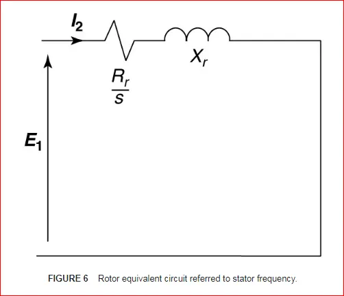
Dividing equation 7-8 by s yields
E1+I2(Rrs+jXr)..................(3)
Equation 3 can be represented by the circuit of Figure 6, which is the rotor equivalent circuit referred to the stator both by turns ratio and by frequency.
 r
r
FIGURE 6 Rotor equivalent circuit referred to stator frequency.
This circuit can be connected to the stator equivalent circuit, but it is instructive to split the resistance into two separate components. For convenience, we can write:
Rrs=Rr+Rrs−Rr ………………..(4)
Combining the last two terms on the right side of equation 4 yields
Rrs=Rr+Rr() ……….........……(5)
Replacing the resistive element in Figure 6 by the two resistive elements on the right-hand side of equation 5 yields the rotor equivalent circuit shown in Figure 7. The reasons for this manipulation will be discussed shortly.
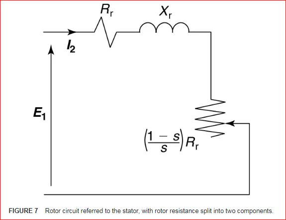
FIGURE 7 Rottor circuit referred to the stator, with rotor resistance split into 2 components.
Finally, by combining the rotor equivalent circuit of Figure 7 with the stator equivalent circuit of Figure 2, we obtain the steady-state equivalent circuit for one phase of a wye-connected induction motor, as shown in Figure 8.
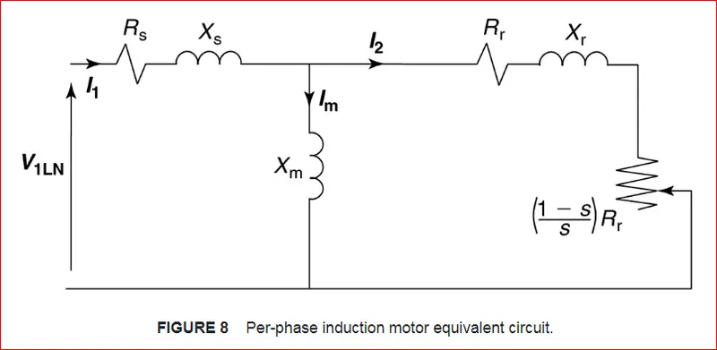
FIGURE 8 Per-phase Induction Motor Equivalent Circuit.
Locking again at the rotor part of the equivalent circuit in Figure 8, the resistor Rr represents the resistance of the rotor winding. The power used by it is the power lost in the resistive heating of the rotor winding. The additional resistive element on the right end is a function of the slip and the rotor resistance. It arises from the necessity to transform the rotor circuit not only by turn’s ratio but also by frequency. The power consumed in this element is the developed power of the machine.
Developed power is the power converted from electrical form to mechanical form and includes the load power plus mechanical losses such as friction and windage.
Subtracting the mechanical losses from the developed power would yield the shaft power, which is the actual power delivered to the load. Developed torque and shaft torque can be calculated from the developed and shaft power, respectively.
NOTES:
CONCLUSION:
- Wkt `(V/F_z ) ∝ ∅`
- In which the frequency is varied and the voltage is made to be constant.
- Therefore from the Plot it is seen that as the frequency increases the maximum Torque reduces and the maximum Speed increases respectively.
- The increasing maximum speed of the motor according to the frequencies is Shown in the command window.
- If the voltage is also varied with the frequency as such, the Flux is maintained a constant then the maximum Torque will be constant until the inverter short time limit.
II. 3 phase, 50 Hz induction motor, represented by equivalent circuit constants X1 = X2 = 0.1 ohm and R1 = R2 = 0.2 ohm is operated at half of rated voltage and frequency. Calculate the ratio of starting torque at half voltage & frequency to rated values.
Given Data:
Number of Phase = 3
Rated Frequency = 50 Hz
Stator Inductance, X1 = 0.1 Ohms
Rotor Inductance, X2 = 0.1 Ohms
Stator Resistance,R1 = 0.2 Ohms
Rotor Resistance, R2 = 0.2 Ohms
To Find:
We need to find the ration of the starting Torque and the half rated voltage and frequency to the same at the rated voltage and frequency.
Solution:
The Equation relating to all the given data is : `T = 3/ω_ms [(V^2 .R_2/s)/((R_1+R_2/s)^2+(X_1 + X_2 )^2 )]`
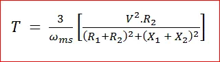
Since we are only required to find the starting torque we can eliminate the term “Slip” (‘s’). This is because at the Starting torque, the motor is 0 and so the Synchronous Speed terms will be cancel each other out meaning the Slip will take a Maximum value of 1.
The Equation of Slip is : `Slip,(s)= (ω_ms-ω_m)/ω_ms`
So we can Rewrite the Torque Equation Omitting the Slip term (s) since its equal to 1.
The Starting torque is given by the Equation: `T = 3/ω_ms [(V^2.R_2)/((R_1+R_2 )^2+(X_1 + X_2 )^2 )]`
Now, we can use this Equation to find the Staring Torque at the Half rated and Full rated Conditions.
Synchronous Speed:
The Formula to find the Synchronous Speed is `ω_ms= (120 .f)/( p)`
Where,
`f` = Frequency.
`p` = Number of Poles.
Let us consider the Number of Poles = n
Let the Half Rated Synchronous Speed = `ω_ms1`
Let the (Full)Rated Synchronous Speed = `ω_ms2`
Half Rated Frequency = `(Rated Frequency)/2 = 50/2 = 25 Hz`
`∴ ω_ms1=(120×f)/n= (120×25)/n = 3000/n`
Rated Frequency = 50 Hz
`∴ ω_ms2 = (120×f)/n=(120×50)/n = 6000/n`
Since, we know that the Rated Synchronous Speed is Double the Half Rated Synchronous Speed, we can express the later in terms of former.
`ω_ms1=ω_ms2/2`
Calculation of Staring Torque at Half Rated Condition:
Now that we have expressed the Half Rated Synchronous Speed in terms of the Rated Synchronous Speed, we will substitute this Expression in the place of Synchronous Speed terms, While calculating the Half Rated Starting Torque.
Since we also varying the voltage between the 2 conditions, Let us assume that the rated voltage is V and that the half rated voltage is V/2.
Let the Half Rated Starting Torque be,`T_s1`
`T_s1= 3/ω_ms [(V^2.R_2)/((R_1+R_2 )^2+(X_1 + X_2 )^2 )]`
Substituting the Expression for Synchronous Speed in terms of the Rated Synchronous Speed:
`T_s1= 3/(ω_ms2/2) [((V/2)^2.R_2)/((R_1+R_2 )^2+(X_1 + X_2 )^2 )]`
`T_s1= 6/ω_ms2 [((V^2/4)×0.2)/((0.2+0.2)^2+(0.1 + 0.1)^2 )]`
`T_s1= 6/ω_ms2 [((V^2/4)×0.2)/(0.04+0.08+0.04+0.04)]`
`T_s1= 6/ω_ms2 [(0.05×V^2)/0.2]`
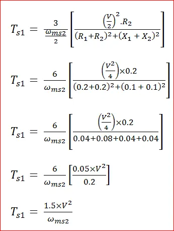
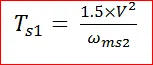
`T_s1= (1.5×V^2)/ω_ms2`
Calculating of Staring Torque at Full Rated Condition:
In this Condition, we will use the Full Rated Voltage (V), the Full Rated Frequency (f) = 50 Hz and the Full Rated Synchronous Speed to Find the Staring Torque. Here we will Substitute the Synchronous Speed at the Full Rated Condition:
Let the Starting Torque under Full Rated Condition be: `T_s2`
`T_s2= 3/ω_ms2 [(V^2×R_2)/((R_1+R_2 )^2+(X_1 + X_2 )^2 )]`
`T_s2= 3/ω_ms2 [(V^2×0.2)/((0.2+0.2)^2+(0.1 + 0.1)^2 )]`
`T_s2= 3/ω_ms2 [(V^2×0.2)/((0.4)^2+(0.2)^2 )] {0.16 + 0.4 = 0.20`}
`T_s2= 3/ω_ms2 [(V^2×0.2)/0.20]×100/100`
`T_s2= 3/ω_ms2 [(V^2×20)/20]`
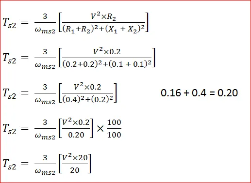
Cancelling 20 From both Numerator & Denominator, We get
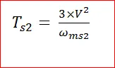
`T_s2= (3×V^2)/ω_ms2`
Comparison of Starting Torque at Both Conditions:
We are required to find the Ratio of the Starting Torque at the Half Rated Condition to the Full Rated Condition.
The Starting Torque at the Half Rated Condition is: `T_s1= (1.5×V^2)/ω_ms2`
The Starting Torque at the Full Rated Condition is: `T_s2= (3×V^2)/ω_ms2`
So, the Ratio of : `: T_s1/T_s2 = ((1.5×V^2)/ω_ms2 )/((3×V^2)/ω_ms2 )`
`T_s1/T_s2 = (1.5×V^2)/ω_ms2 × ω_ms2/(3×V^2 )`
`T_s1/T_s2 =1/2`
Therefore, the Ratio of the Starting Torque at the Half Rated condition to the Full Rated Condition is `1/2` or 0.5 .
III. Make a comparison of square wave inverter output voltage with sine modulated one.
Abstract –
In many applications Alternating Current is preferred over Direct Current but as we see that we cannot store energy in the form of Alternating current. It is always stored in the form of Direct Current. To use this stored energy a device is required to convert DC energy into AC energy. The device which does this is called an inverter. Single phase inverter or three phase inverter are two types of inverters. Single phase inverter has again classified as half bridge inverter and full bridge inverter. In this paper we studied different types of the inverters and there harmonics contains. Square wave, modified sine wave and pure sine wave are single phase inverter techniques and are mainly discussed in this paper and compared for their suitable use. Square wave or modified-sine wave are generally used types of inverters. For low and medium power applications square wave or modified sine wave inverter can be used. Pure sine wave inverter has less harmonic distortion and more accurate.
INTRODUCTION
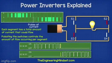
An inverter or power inverter is a device which converts direct current (DC) to alternating current (AC). There are three types of inverters based on type of output waveform as: square wave, modified-sine wave and pure sine wave. A square wave is non sinusoidal waveform, most typically seen in electronics and signal processing. Square wave have two levels (positive and negative) and alternates regularly between these two levels. The output of a modified sine wave inverter is more like a square wave output except that it has one more level i. e, before switching positive or negative the output goes to zero volts. Though it is simple and low cost, most AC motors work on this power source or inverter reduces efficiency and the motors may also produce hissing sound while operating and due to which the life of equipment will reduce. A pure or true sine wave inverter changes or converts the DC supply into a near perfect sine wave. The sine wave has very little harmonic distortion which results in a very clean supply and makes it suitable for working electronic systems such as computers, motors and microwave ovens and other sensitive equipment without causing problems like noise. Things like mains battery chargers also run better on pure sine wave converters. Ideally the output waveforms of an inverter should be sinusoidal. However, the waveforms of practical inverters are non sinusoidal and contains certain harmonics. Due to the availability of high speed power semiconductor devices, the harmonic contents present in the output voltage can be minimized significantly by using switching technique. BJTs, MOSFETs or IGBTs can be used as ideal switches.
(I) According to the Output Characteristic
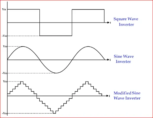
According to the output characteristic of an inverter, there can be three different types of inverters.
- Square Wave Inverter
- Sine Wave Inverter
- Modified Sine Wave Inverter
1) Square wave inverter
The output waveform of the voltage for this inverter is a square wave. This type of inverter is least used among all other types of inverter because all appliances are designed for sine wave supply. If we supply square wave to sine wave based appliance, it may get damaged or losses are very high. The cost of this inverter is very low but the application is very rare. It can be used in simple tools with a universal motor.
2) Sine wave
The output waveform of the voltage is a sine wave and it gives us a very similar output to the utility supply. This is the major advantage of this inverter because all the appliances we are using, are designed for the sine wave. So, this is the perfect output and gives guarantee that equipment will work properly. This type of inverters is more expensive but widely used in residential and commercial applications.
3) Modified sine wave
The construction of this type of inverter is complex than simple square wave inverter but easier compared to the pure sine wave inverter. The output of this inverter is neither pure sine wave nor the square wave. The output of such inverter is the some of two square waves. The output waveform is not exactly sine wave but it resembles the shape of a sine wave.
| COMPARISION OF INVERTER WAVE TECHNIQUE |
| PARAMETER | SQUARE WAVE | MODIFIED SINE WAVE | PURE SINE WAVE |
| OutPut Waveform | Square wave. | Square except that the output goes to zero volts for a time before switching positive or negative wave. | Sine wave. |
| Harmonic Distortion | More. | Moderate. | Less. |
| Power Loss | More. | Moderate. | Less . |
| Heat Generation | More. | Moderate. | Less. |
| Design Complexity | Simpler. | Less complex design than pure sine wave. | More Complex. |
| Cost | Less Expensive. | Moderate Expensive. | More expensive. |
| Suitability | Not appropriate to delicate electronic devices. | Not appropriate to delicate electronic devices. | Appropriate to delicate electronic devices. |
Sine wave advantages over square wave
Sine wave inverters are more efficient than square wave inverters, when it comes to the conversion of DC to AC. This ensures that the power loss is minimized, due to greater efficiency. As a consequence, your electricity bill does not shoot up. This is an immediate benefit of using a sine wave inverter. There are other long-term advantages too, which we will discuss below.
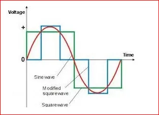
The red line in the figure represents a sine wave while the green one shows the current alternating in a square wave. You can see the smooth change-over of a sine wave. This is the same kind of power that the grid supplies. Since your inverter is going to be a substitute for grid power, it is important for the kind of power be the same.
Benefits of using sine wave inverters
- A sine wave minimizes the risk of damage to your sensitive appliances. Compared to a square wave, there is very little harmonic distortion in a sine wave—essential for expensive equipment.
- Devices that use control circuits, which sense the phase for speed/voltage control, or devices that sense instantaneous zero voltage crossing (for timing control) must have a sine wave supply. As you can make out from the figure above, sine wave changes polarity instantaneously and smoothly, when it crosses zero volts. The rise and fall of voltage is smooth as compared to the shape of the square wave. Due to this feature, inductive loads (as in motors or microwaves) run quieter, cooler and faster.
- Electronic items like printers, scanners and monitors have minimal harmonic distortion. Therefore, fewer glitches and irregular printouts are assured. This is important for sensitive commercial applications too. Even fans, audio amplifiers, TV etc. produce less audible noise in sine wave v/s square.
NOTE's: https://drive.google.com/file/d/1d6tGMGv3gJTJllVJdp60mdQqPG5UErwN/view?usp=sharing
REFERENCE :
- http://www.zelect.in/inverter/square-wave-inverter-vs-sine-wave-inverter
- https://www.youtube.com/watch?v=iIqhAX0I7lI
- http://52.172.159.94/index.php/ijird/article/viewFile/36611/29550
- https://in.mathworks.com/help/autoblks/ref/inductionmotor.html
- https://circuitdigest.com/tutorial/different-types-of-inverters