Challenge 8
Ans 1
Piers are part of the substructure where the forces from superstructure are transferred to the ground.
- Piers are compression members of a bridge
- Support the span by taking loads from the bearings through pier cap
- Members subjected to axial loads and moments in both directions
Loads considered in calculating the total design force in a pier of a metro viaduct:
- Dead load or self-weight of the structure
- Super Imposed Dead loads (SIDL)
- Live loads or Train loads with four different load cases OTOS, OTBS, BTOS,BTBS
- Braking and Traction load
- Centrifugal load
- Wind load
- Earthquake load
- LWR (Long welded rail) load
- Derailment load
- Temperature loads
Ans 2
Dead load (DL)
It consists of self-weight of the girders, pier caps and the pier itself
Super Imposed Dead loads (SIDL)
It consists of the rails, third rail (if any), plinth beam of track, parapet load, cable trays and troughs, cables, handrails, etc. as specified in DBR
Live load (LL)
Live load is nothing but the moving wheel load of the trains moving on the metro viaduct. There are 4 load cases to be considered while applying loads for the pier of a metro viaduct. There are 2 live tracks for the metro where trains run on both sides in either direction.
One track one side (OTOS):
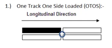
If LHS and RHS side of the circle are 2 spans, then as per figure above, OTOS represents only one train at the LHS side and no trains on the RHS side. That is LHS side single track.
One track both side (OTBS):
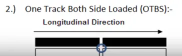
If LHS and RHS side of the circle are 2 spans, then as per figure above, OTBS represents one train at the LHS side and one train on the RHS side. That is single track on both LHS and RHS of pier.
Both track one side (BTOS):
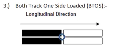
If LHS and RHS side of the circle are 2 spans, then as per figure above, BTOS represents both trains at the LHS side and no train on the RHS side. That is double track (both) on LHS of pier.
Both track both side (BTBS):
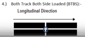
If LHS and RHS side of the circle are 2 spans, then as per figure above, BTBS represents both trains at the LHS side and both train on the RHS side. That is double track on LHS and RHS side of pier.
Grade of concrete generally used for construction of piers is M50.
Ans 3
Braking force in the design of a metro viaduct:
The force acting on the viaduct and its structural components when the train applies brakes to slow down / stop its motion is called as braking force/load. Braking force is the result of friction between wheels and the rails. The rails then transfer this load to the structure via plinth beam. Generally braking force is taken as 18% of all maximum unfactored vertical loads.
Traction force in the design of a metro viaduct:
The force acting on the viaduct and its structural components when the train starts to accelerate from rest position or moving position is called as tractive force/load. Tractive force is the result of friction between wheels and the rails. The rails then transfer this load to the structure via plinth beam. Generally tractive force is taken as 20% of all maximum unfactored vertical loads.
Ans 4
Centrifugal force:
When there is a curved alignment of the bridge, there is a force acting on the train outwards from the centre of the circle of the curve. This outward force is called as centrifugal force and it acts on the train which in turn transfers the same on the bridge through the rails.
It is a function of the velocity of the train allowed on that curve (as per design) and the radius of the curve. Co-efficient of centrifugal force is given by: V2/(127*R). Thus centrifugal force is product of vertical load and this co-efficient.
Centrifugal force acts at the CG of the metro train horizontally outwards and the CG is generally ~ 1.83 m above the rail level. However, this value can change as per metro project.
Wind load:
Wind loads are loads exerted on the superstructure and substructure on account of longitudinal and/or transverse winds flowing through the area where the viaduct is constructed. A preliminary basic wind speed of the area is assumed and the calculations of wind pressure on the structure is made.

(Wind without LL):
When there is very high wind flowing across the area under consideration, it is practically not possible for the movement of the train. Thus, we consider its design as “without LL” which means that the operations of a metro may be stopped / halted temporarily. The wind pressure will be very high and structure to be designed for that with applicable load combinations. Thus, it means that there will be no forces such as braking/traction, centrifugal, derailment, etc. in those combinations since the train is not moving even though present on a span.
(Wind with LL):
In this case, the wind speed flowing across the area under consideration is low and the train operations are normal. In other words, all the loads mentioned above need to be combined as per the applicable combinations although the wind pressure exerted would be relatively low.
Ans 5
Earthquake load
This is a load acting on the structure on account of a seismic event (an earthquake). India is divided into five seismic zones I, II, III, IV and V. Currently, seismic zone I does not exist. The most severe zone is V and other zones in descending order of severity. The seismic force on a particular structure or a metro viaduct also depends on the stiffness of the structure and its mode of vibration or natural frequency.
Three types where seismic loads are considered are as follows:
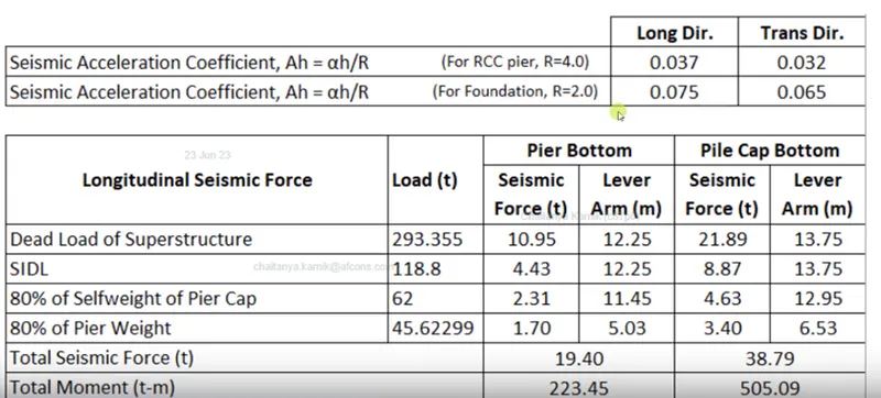
- For earthquake in the longitudinal direction, the live load can be ignored since the train can just roll away in that direction. Hence, the mass contribution of the train can be ignored.
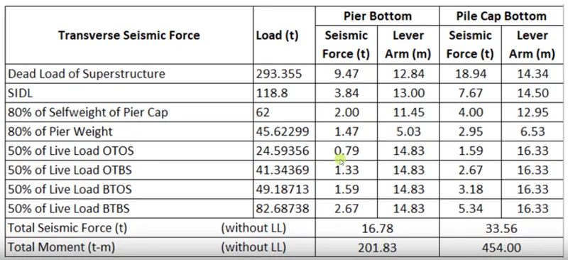
- In the transverse direction with LL, the wheels are locked against the rails and LL mass contribution shall be considered at locations where the train is present.
- There may also be a case where the train is absent in few spans during a seismic event which is classified as earthquake in the transverse direction without LL and even though the mass participation of LL is absent, the compressive effect due to LL will be reduced on the substructure leading to increased tension.
Seismic loads are computed as per following procedure:
1. Base shear Ah is given as [ZI / (2R) * Sa/g)] where the different parameters are as listed below.
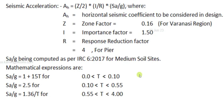
2. Here the unknown entity is the Time period ‘T’ of the structure which depends on the mode of vibration (stiffness) of the structure and can be computed as per following table.
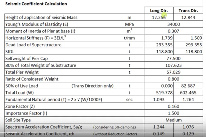
3. After getting the time period ‘T’, we get the Sa/g ratio as shown in earlier table of IRC 6:2017. Hence, the actual seismic co-efficient can be found. The following table shows the summary for arriving at bending moments and shear as per the corresponding seismic co-efficient in longitudinal and transverse direction.
Ans 6
LWR forces
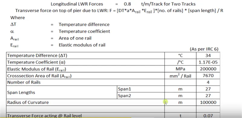
LWR stands for long welded rails. In a metro viaduct, generally there is an expansion joint at every 27.0 ~ 28.0 m. However, the rails present on the top are welded for a large length. In other words, they do not have the liberty to expand or contract like the structure. This causes stresses to be locked in the rails due to increase and decrease in the temperature or even due to the creep of concrete.
Calculation of forces: The forces of LWR are generally taken as 0.8 t/m per track. The above magnitude is a result of research and analysis which is called as rail structure interaction. For two U-girders (tracks) on either side of a pier with 27.0 m spans, the total load on pier at rail cg would be half contribution from either span girders ~ 0.8 t/m x (27/2 + 27/2) x 2.0 = 43.2 t
For a curved alignment, this LWR load also acts in the transverse direction.
For a temp. difference of 34 degree, and a standard steel rail (E=2*10^5 Mpa, Ar = 7670 mm2) with thermal co-eff. α , transverse force at rail level is given as follows:(see extract below)
Derailment loads
As the name suggests, this load is taken into the design when the train gets derailed from its track due to some reason. For instance, if the speed is not controlled on a curved alignment, then the train might go off the tracks and land on the web of a U-girder or the parapet in case of an I-girder. This will cause an impact on the side walls/web and the soffit of the U-girder in areas which are not considered to be loaded b forces from the train. Local checks for stresses need to be satisfied for these loads.
Ans 7
Design combinations of all loads in a metro design:
Table for SLS:
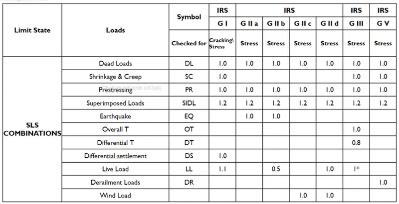
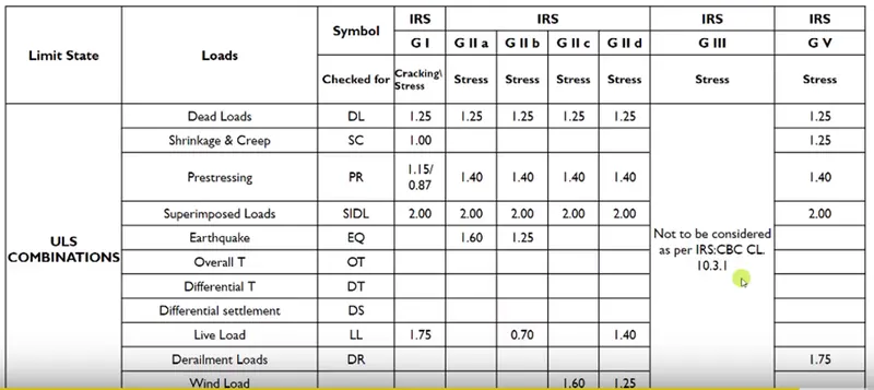
Table for ULS:
For SLS case, 7 combinations are used viz. GI, GIIa, GIIb, GIIc, GIId, GIII, GV
For ULS case, 6 combinations are used viz. GI, GIIa, GIIb, GIIc, GIId, GV
G stands for “Group”.
Loads to be considered are Dead loads, SIDL, Live loads, Wind loads, Earthquake loads, Pre-stressing loads, Creep and shrinkage loads, Derailment loads, Differential temperature loads, Differential settlement loads, etc. The table for combinations is self-explanatory.
Few points to note for both load combinations-
SIDL has a higher factor than the dead load since the SIDL cannot be predicted as accurately as the Dead loads and also there is possibility of additional coat of wearing coat which can be there after a period of time.
Live load has a factor of 1.1 since it is also a variable load with probability.
If earthquake factor is considered, then derailment load / wind loads are not considered and vice versa since the code says that all occurring at the same time has extremely low probability (GIIa) or with some LL (GIIb).
GIIc and GIId are combinations with wind and without earthquake without live load and with live load respectively.
GV is an accidental load case where derailment of train is considered and no wind/earthquake.
GIII combination is not to be considered in ULS combination as per IRS: CBC Cl 10.3.1. This is because in the event of an ultimate state being reached, the locked-in stresses due to temperature get dissipated and are no longer stored inside the structure.
Ans 8
SIDL has a higher factor than the dead load since the SIDL cannot be predicted as accurately as the dead loads. Also, there is possibility of additional wearing coat in road bridges which can be there after a period of time during repairs and maintenance. In metro bridges, there can relaying of items such as cables of larger diameter, guard rails, parapets, etc.
Ans 9
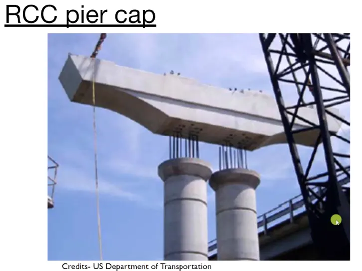
Basic design parameters for design of an RCC pier cap:
- Distance between bearings in transverse direction
- Eccentricity of alignment centreline with respect to pier centreline
- Span on both sides of the pier
- Volume of the pier cap for getting the weight
- Horizontal distance between CG of pier and CG of pier cap in transverse direction
- Vertical distance between bearing bottom and CG of pier cap
- Characteristic compressive strength of concrete, fck
- Density of concrete
- Horizontal distance between bearing centreline and pier cap centreline in the longitudinal direction
- Height of retainer or shear key
- Lever arm of DL, SIDL, LL from CG of pier cap (or distance between CG of loads to CG of pier cap)
Ans 10
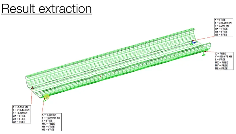
Reactions for one of the ULS load combination:
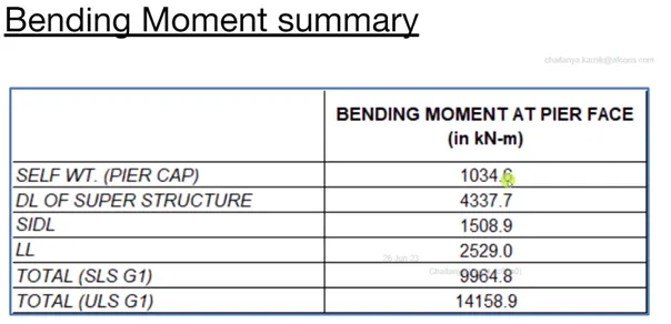
Design bending moments:
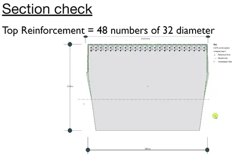
Reinforcement cross section showing 48 bars:
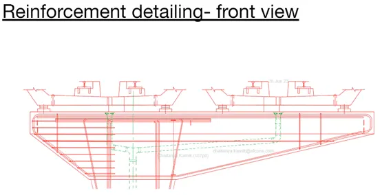
Reinforcement detailing – longitudinal elevation & transverse section
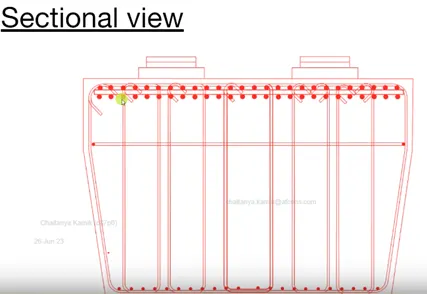
- Reinforcement is provided as 48 bars of 32 dia. on top fibre in two layers for the hogging bending moment.
- First layer of 24 nos. bars of 32 dia. are provided as a closed loop from top to bottom and on sides.
- Second layer of 24 nos. of 32 dia. bars are provided as a straight line below the first layer.
- Drainage pipe infringement with the main r/f needs to be checked and note to be added stating that wherever the pipe does not fit between the clear spacing of r/f, spacing to be adjusted without compromising the nos. of total bars.
- Since the pier cap shown is an eccentric one, one can say that LHS side is a corbel since the eccentricity of load from pier face is less than the depth of the pier cap. The concept of corbel is such that there is a possibility of some load to flow directly through compression and some through shear-flexure unlike in a pure cantilever where load flows purely through shear-flexure.
- To avoid crushing of concrete through direct compression, horizontal r/f links are provided to ensure limiting the load flow by compression.
- Further, shear links or shear reinforcement are provided at certain spacing depending on the shear design requirement in the cantilever RHS portion. These vertical needs are bent at an angle of 135 degrees at the ends for ensuring proper seismic detailing.
- Again, vertical reinforcement bars are provided at the junction of pier and pier cap (seen also earlier protruding out of pier, in figures of erection of precast pier cap). These provide the necessary force transfer to the pier by action of shear-friction effects. These rebars are very important since they also transfer all the horizontal loads from the superstructure bearings like breaking-traction, wind, seismic, etc. to the pier.
- Below the bearing pedestals, there is a meshing reinforcement provided to avoid direct crushing of concrete which is present just below the pedestals. This possibility is there since all the high vertical loads are transferred here practically as point loads. Same meshing reinforcement must be provided below the locations of the jacks that are to be used during bearing replacement. The r/f is generally of 8 dia. bar mesh.
- Spacer r/f is provided between the two layers of top longitudinal reinforcement. The dia. of spacer bar should the minimum of the dia. of the bars in the top or bottom layer.
- Horizontal bars are also provided all around the periphery of the cross section at fixed intervals as a closed loop to tie all the load carrying rebars and maintain proper spacing between them.
To summarize there are:
- Longitudinal main reinforcement – top tension, bottom compression for flexure
- Vertical shear reinforcement
- Horizontal links for corbel transferring direct compression
- Vertical shear reinforcement between pier and pier cap
- Meshing reinforcement below pedestals and jacking points on cap
- Spacer bar between 2 consecutive layers
- Peripheral vertical and horizontal bars to maintain spacing and help in tying of main bars
Section can be optimized considering the design M/Mu ratios, stress checks in concrete and reinforcing steel and the allowable crack width.