Challenge 4
Ans 1
Prestressed I-girders are mainly bridge girders wherein the design bending moments are counteracted mainly by the prestressing steel in the cross section. These girders are mainly of two types – post tensioned girders and pre tensioned girders.
For double deck bridges the I girders can be preferred because of the reasons as listed below:
- Sufficient structural clearances: The bridge to be built on top of the existing bridge shall require some minimum headroom i.e. clearance between soffit of the beam on top to deck of the bridge at the bottom. This structural clearance is about 5.5 m minimum and can be achieved by means of multiple I-girders. Because more number of girders would mean lesser loads on individual girders and proper load distribution.
(See fig double deck bridge)
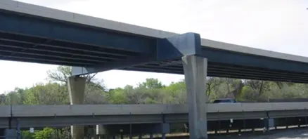
- Minimum hindrance to existing traffic during erection: Since the bridge on top is to be built at some substantial height which may cross the standard erection criteria, the weight of the girders can be controlled by means of multiple I-girders and erection of the farthest girder can be done without any problem.
- Curvature in top bridge: The bridge curvature if any required can be easily achieved by providing I-Girders between two piers in slightly eccentric position and managing the curve by cast-in situ deck slab.
- Prestressing: Prestressed I-girders have lesser depths as compared to RCC girders. Further, two stage stressing of the girders i.e. first stage for erection and second stage after casting deck slab can be used to further keep the depths in check.
Ans 2
Load flow behaviour in a pre-stressed concrete I-girder:-
- Loads as defined in DBR such as SIDL, self-weight of girder, live loading of trains (axle loads) are acting on the I-girder which is simply supported on the two piers.
- Longitudinal design: Flexure and shear
The loads create a bending moment on the I-girder in the global direction along the major axis. Resistance to bending moment is provided by the cross section of the I-girder. Moreover, soffit consists of pre-stressing cables in the longitudinal direction which provides the major resistance to the tension generated by global bending.
Shear is designed to be taken by the webs of the I-girder. Mainly the shear is considered to be acting at the end portion for a simply supported I-girder.
- Transverse design: Flexure Only
The deck slab is supported on top of the I-girders effectively between the flanges and it is designed in such a way so as to resist only flexure and not shear. This is mainly since the depth of the deck slab is ~ 250 mm (as governed by its span) and it is difficult from a construction point of view to accommodate shear reinforcement in such a limited depth already consisting of doubly reinforced sections with clear covers of ~ 40 mm top and bottom.
Also since there is an age gap between the casting of the I-girder and the deck slab, there is a longitudinal creep and shrinkage effect. This effect along with the longitudinal temperature gradient loads are the reason for which the substantial reinforcement has to be provided in the deck slab in the longitudinal direction also.
- Other loads such as transverse wind loads, etc. are designed to be taken by the I-girder in its minor (transverse) axis.
Ans 3
Relevant Codal Provisions:
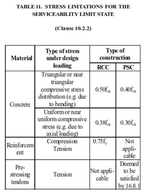
Table 11 (Clause 10.2.2) of IRS CBC: Stress limitations for serviceability limit state in concrete, reinforcement and pre-stressing steel.
IRS CBC Section 16.4.3.1: Permissible moment ratios (strength)
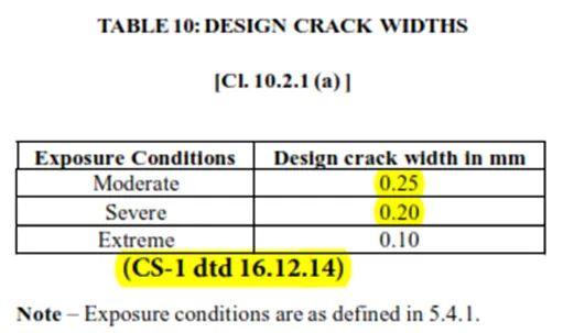
Table 10 (Clause 10.2.1 a) of IRS CBC: Allowable crack widths
Ans 4
TABLE 11: STRESS LIMTATIONS FOR THE SERVICEABILITY LIMIT STATE - (Clause 10.2.2)
0.5fck and 0.38 fck clause for RCC: Due to triangular compressive stress distribution on account of bending, the average stress across the section is not uniform and hence there is some margin capacity left in the section. A value of 0.5fck is thus permitted in RCC for bending stress which is higher than 0.38fck allowed for direct compression which has rectangular stress distribution where margin capacity is not there.
0.4fck and 0.3fck clause for PSC: On similar grounds of compressive stress distribution, different permissble limits are there for compression by bending and direct compression in PSC beams also viz. 0.4fck and 0.3fck respectively.
Difference between RCC and PSC structures is that in RCC, the maximum design stresses are considered to be reached when the most critical load combination occurs which might be a rare occurrence during service. However, in PSC, the maximum design stresses are considered to be reached when the girder is presstressed to its design value in casting yard itself. When live loads are actually applied in service, the stresses are relieved.
Also, lesser stress limits are there for PSC girders so that they do not buckle under prestress loads in the casting yard. Hence, higher permissible limits are given for RCC and tighter for PSC.
Ans 5
Design crack width is nothing but the dimension of a structural crack in a reinforced concrete section subjected to tensile loads and exposed to different environmental conditions.
The requirement to restrict this crack width is:-
- To prevent the reinforcement from getting exposed to external weather.
- For serviceability such that it should not affect the durability.
- Should not be visible to the eyes as it gives a bad idea about the structure.
Clause 5.4.1
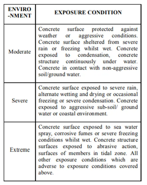
As per IRS CBC Code different allowable limits are given for crack width in conditions such as moderate, severe and extreme. 0.2mm crack width is the maximum allowed as per table 10 of IRS CBC.
Further the exposure conditions are given in Clause 5.4.1 as shown above, citing the city of Mumbai, we can refer to it as the extreme exposure condition as it experiences severe rain and is exposed to sea weather conditions.
Ans 6
A crossover in railways is a junction where two trains or two tracks cross each other at some inclination. It is generally to facilitate the train to enter / exit from a junction station / terminal station.
The crossovers points are known to the designer beforehand and thus the design of girders at that location is planned accordingly.
I-girders are preferred at crossovers over U-girders due to following reasons:
- In a two separate U-girder system, there are two inner webs which will hinder the crossing of the track / trains from one U-girder to another. Hence in such a case I-girders are used with common deck slab.
- Width of the deck slab on top of I-girders can be tailor made based on the structure gauge envelope which is an imaginary outline showing the maximum outer dimensions within which a train would move (cross) in addition to the cable trays on the outside.
Ans 7
SIDL: Super Imposed Dead Loads are the ones which are present on the structure permanently other than the self-weight of the structure. SIDL consists of following generally:
- Plinth load
- Rails + rail pads
- Parapet loads as cantilever UDL
- Third rail load, if third rail is present
Ans 8
Staad file
Ans 9
|
Cable No |
No. of strands |
Eccentricity from bottom fiber(m) |
|
1 |
14 |
0.150 |
|
2 |
13 |
0.370 |
|
3 |
13 |
0.590 |
|
4 |
13 |
0.810 |
CG of strands from bottom fibre at mid-section is as follows:
CG from bottom fiber = (14*0.15 + 13*0.37 + 13*0.59 + 13*0.81) / (14+13+13+13)
= 0.474 m
Total no. of strands = 14+13+13+13 = 53 nos.
Pre-stressing force applied = 0.765 * fpu *Area of one strand * nos. * (1-Loss%)
= 0.765*1860*140*53*(1-0.175)
= 8710.28 kN
Since there is ambiguity in data, assumptions are made as follows:
I = 0.90 m4
Ybot = 0.594 m
Area of cross section = 0.55 m2
Mz = 10,000 kN.m
Z = I/ybot = 1.515 m3
COG of section (ybot) to COG of strands = eccentricity (e)
= 0.594 – 0.474 = 0.12 m
Stress at bottom fiber = P/A + Pe/z – M/z
= (8710.28/0.55) + 8710.28*0.12/1.515 – 10,000/1.515
= 9.926 N/mm2