Challenge 5
Ans 1
Step by step procedure for transverse analysis:
- Geometrically verify the dimensions of the slab, I-girders, rails, plinth beams, parapet, etc.
- Model the slab in design software such that it spans between the girders in the transverse direction of the bridge. The girders act as supports.
- Assign the sectional properties (cross sectional dimensions). Here the width can be 1.0 m.
- Assign the various loads and load combinations to the model
- Extract the results for the various forces at support locations and at mid spans.
- Design the slab i.e. provide reinforcement in longitudinal direction of slab and transverse direction (long direction of bridge for thermal gradient, creep and shrinkage)
Ans 2
STAAD steps involved in modelling of nodes, beams and supports:-
- Create a new model in staad. Importantly, check the units as desired by design engineer.
- As per the actual geometry, measure
- the distances between girders and
- cantilever outstand of the slab on both sides of girders
- Origin node 0,0,0 can be modelled as the extreme left edge of the slab. Select CREATE NODE command in staad for this purpose
- Followed by modelling next node of slab at girders and at last in the end the extreme right edge of the slab. Nodes to be modelled in the global X-direction of staad.
- Connect all these nodes by the ADD BEAM command.
- CREATE SUPPORT command can be used for creating pinned support and the nodes showing locations of girder to be assigned with supports.
Ans 3
Values of loads for assigning on deck slab model:
- Self-weight: This is the dead weight of the structural slab and once assigned STAAD will take the weight as per the sectional properties entered
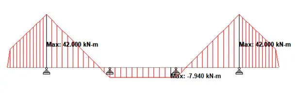
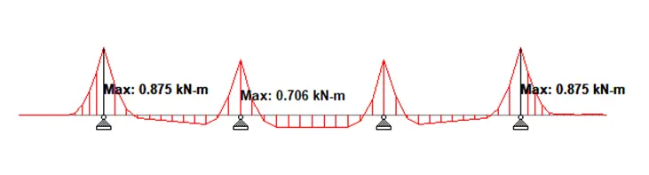
- SIDL: SIDL can be calculated considering the weight of the rail, rail attachments, plinth beam load, etc. With the 45-degree load dispersion from the plinth beam to the deck slab, say ~ 1.0m is the dispersed width, then the load is applied as a UDL on the slab for ~ 1.0 m length at all supports. This can be in the range of ~ 7kN/m. Further, SIDL of parapet can be split from the above since the erection of parapet and deck slab happens at different times and is better for stage pre-stress check. This parapet load is applied on edge of slab as an eccentric bracket with point load and concentrated point moment ~ 24 kN and 24*0.5 = 12 kN.m respectively. (Loads are per meter width of slab)
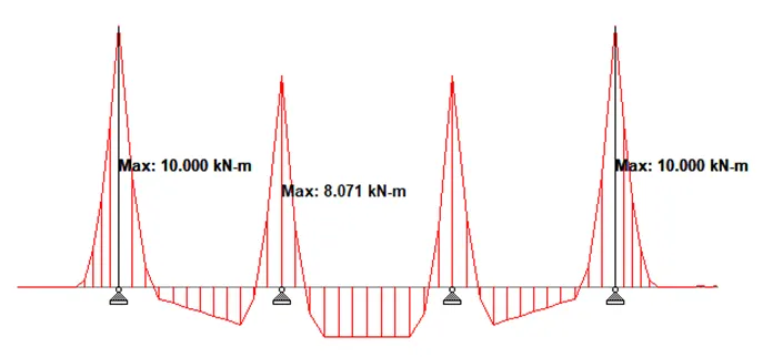
- Live load: On similar grounds as point no. 03, live load of the train can be applied on slab as UDL of ~ 80kN/m. This live load is split into 3 cases viz. live load of train on one side, live load of train on other side and live load of train on both sides.
- SLS load combinations:
Case 101- 1.0*Self-weight + 1.2*SIDL + 1.1*Live load A
Case 102- 1.0*Self-weight + 1.2*SIDL + 1.1*Live load B
Case 103- 1.0*Self-weight + 1.2*SIDL + 1.1*Live load A+B
Case 104- 1.0*Self-weight + 1.2*SIDL
- ULS load combinations:
Case 201- 1.25*Self-weight + 2.0*SIDL + 1.75*Live load A
Case 202- 1.25*Self-weight + 2.0*SIDL + 1.75*Live load B
Case 203- 1.25*Self-weight + 2.0*SIDL + 1.75*Live load A+B
Case 204- 1.25*Self-weight + 2.0*SIDL
Ans 4
Staad model is attached for reference.
Since we do not have concrete freeware design software and not the scope of this course, attaching the screenshots for bending moment extracted below.
Self-weight
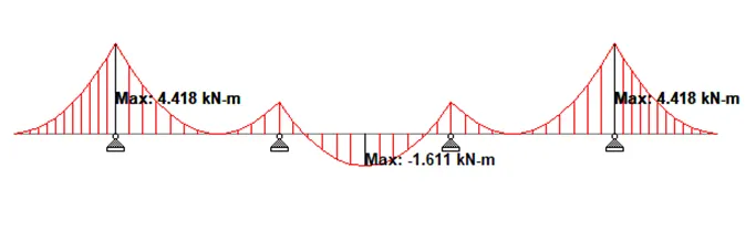
SIDL
Parapet load
Plinth load
Live load A+B
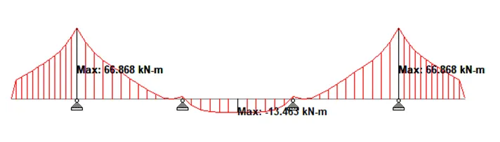
SLS A+B COMB
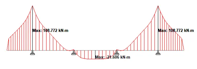
ULS A+B COMB
SLS max moment case will be governing for checking the material stresses of concrete and rebar steel and calculating the crack width of the section.
ULS max moment case shall determine the M/Mu ratio which shall be less than 1.
For designing the reinforcement, Maximum ULS bending moment.
Steel reinforcement can be as shown below:
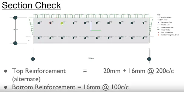
20 dia and 16 dia bars are provided @ 200 c/c alternate at top for the maximum hogging moment as per the figures shown above (109 kN-m)
16 dia bars are provided @ 100 c/c at bottom for the maximum sagging moment as per the figures shown above (22 kN-m)
Reinforcement shall also be provided in the longitudinal direction of the bride for temperature gradient, creep and shrinkage effects.
Ans 5
Diaphragms are structural RCC members connecting the PSC I-girders at various intervals and at ends. The diaphragms located at the ends of the I-girder are called End diaphragms whereas those located at intermediate locations in the span are called Mid diaphragms.
End diaphragms are always present in the span to resist the buckling of the girders at ends.
Mid diaphragms may or may not be provided between the girders depending on the span and the moment of inertia about the minor axis.
Ans 6
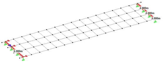
The end diaphragms are connected between the I-girders and are cast along with the deck slab. The grade is kept same as that of the slab. During the grillage modelling of the PSC I-girders, diaphragms were modelled and the intersection of I-girders and diaphragms were the points where supports were assigned. (See figure below: red coloured beams are end diaphragms)
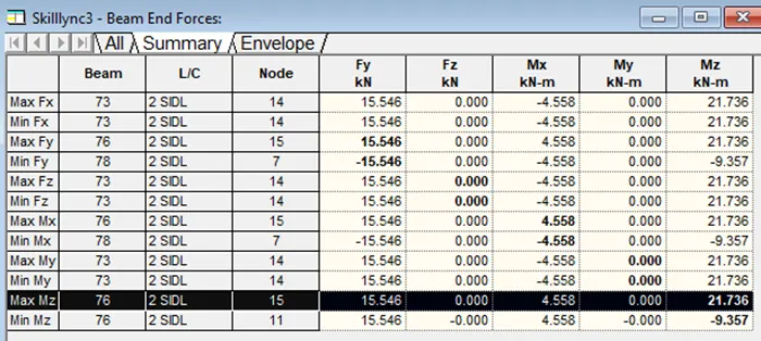
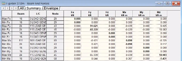
Bending moments as per staad are shown below:
Self-weight
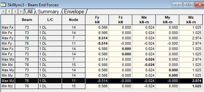
SIDL
Live load
A. Hogging bending moment (+) in SLS combination
Impact = 1+ (0.15+(8/(6+L)))*0.72, if span = 25.6 m, then
I = 1.2903
M1 sls = 1.0*DLM + 1.2*SIDLM + 1.1*LLM*Impact
= 1*2.974 + 1.2*21.736 + 1.1*18.903*1.2903
= 55.89 kN-m
B. Sagging bending moment (-) in SLS combination
Impact = 1+ (0.15+(8/(6+L)))*0.72, if span = 25.6 m, then
I = 1.2903
M2 sls = 1.0*DLM + 1.2*SIDLM + 1.1*LLM*Impact
= 1*0 + 1.2*9.36 + 1.1*1.431*1.2903
= 13.26 kN-m
C. Hogging bending moment (+) in ULS combination
Impact = 1+ (0.15+(8/(6+L)))*0.72, if span = 25.6 m, then
I = 1.2903
M3 uls = 1.25*DLM + 2.0*SIDLM + 1.75*LLM*Impact
= 1.25*2.974 + 2.0*21.736 + 1.75*18.903*1.2903
= 89.87 kN-m
D. Sagging bending moment (-) in ULS combination
Impact = 1+ (0.15+(8/(6+L)))*0.72, if span = 25.6 m, then
I = 1.2903
M4 uls = 1.25*DLM + 2.0*SIDLM + 1.75*LLM*Impact
= 1.25*0 + 2.0*9.36 + 1.75*1.431*1.2903
= 21.95 kN-m
Ans 7
During the maintenance period of the bridge like inspection and/or replacement of the bearings, the bridge span needs to be lifted up. Since the only available space above pier cap is between the existing bearings, the jacks have to be placed under the end diaphragms. Therefore, the end diaphragms must be designed for the jacking case of the bridge in addition to normal service design.
Usually, the jacks are placed at a distance of ~ 650 mm from the center of the I-girder. A designer must ensure that this distance adopted in design is sufficient for the base of the jack to rest beside the girder.
Ans 8
Staad file is attached as reference.
Ans 9
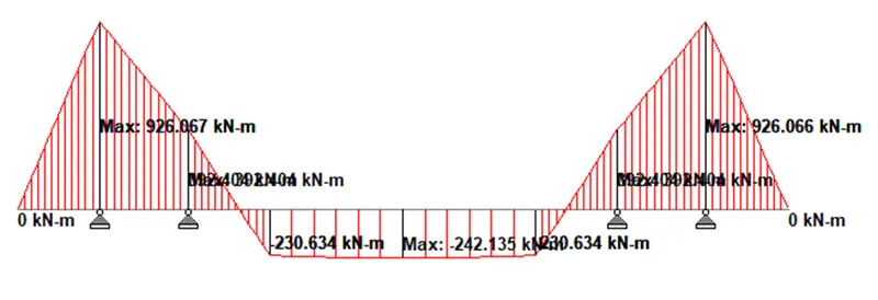
Following bending moment diagram can be observed for jacking case of diaphragm:
SLS: 1.0 DL + 1.2 SIDL
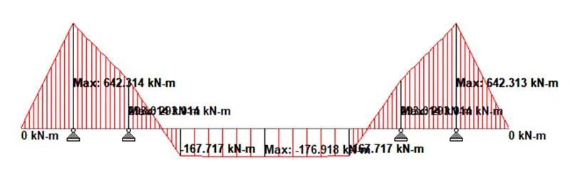
ULS: 1.25 DL + 2.0 SIDL
For checking that our section is safe, following are the parameters:
- The diaphragm is checked as a T-section and reinforcement is provided at top for Hogging ~ 926 kN-m and at bottom for sagging ~ 230 kN-m
- At Service, we have to check the stresses in concrete, reinforcement steel and the crack width.
For concrete, the allowable stresses at SLS are 0.5*fck, so for M50 grade, our stresses should be less than 25 Mpa
For reinforcement, the allowable stresses at SLS are 0.75*fy, so for Fe550 steel, our stresses should be less than 412.5 Mpa
Allowable crack width for different exposure conditions are given in IRS CBC subject to a maximum of 0.2 mm.
- At ULS, we must ensure that the moment capacity of the section is greater than the bending moment at ULS, in this case greater than 926.066 kN-m
NOTE:
In design and analysis of diaphragm, it is thus observed that the jacking case is far more governing in SLS and ULS with respect to normal case in spite of the fact that there is no live load.