Challenge 2
Ans 1
Following are the structural components of the bridge:-
- Superstructure - It carries the train loads directly over it and connects two piers. Types based on span arrangement - U girders, I-girders, Box Girders, Composite Girders etc. All the utilities of the metro, crash barriers, SIDL, live loads, etc are analyzed to travel on top of this system.
- Bearings - Used to transfer the loads from the superstructure to the substructure. Types of bearings based on span are are Elastomeric, Spherical, Pot PTFE, etc. Further, based on behaviour / restraint requirements they can be fixed/free.
- Substructure - Consists of pier cap, pier and foundations (open/pile/well). Substructure transfter the loads from superstructure to the ground. The substructure design is structurally as well as geo-technically verified.
- Abutments - Substructure element provided at ends of a bridge to transfer loads and retain the slopes.
Ans 2
Super Imposed Dead Loads (SIDL):- These loads are permanent loads acting on the bridge other than live loads or selfweight of the structure. These include crash barriers, sleepers, third rails, OHE masts, water pipelines, other utilities as envisaged in DBR. Further they can split as fixed SIDL and variable SIDL and can be analyzed with separate load factors.
Ans 3
Following are the different types of girders for a metro viaduct chosen based on span arrangement and/or construction sequence:-
1. U-trough girders - pretensioned
2. Box girders - post tensioned
3. I-girders - Pre/post tensioned
4. Steel Composite girders - Steel plate girders+cast in-situ deck slab
5. Truss girder - Open web / closed -Steel truss
Ans 4
Bearings transfer the loads from the superstructure to the substructure. Types of Bearing are as follows:-
- Elastomeric Bearing - These bearings consist of alternate layers of elastomers (rubber pads) and steel plates sandwiched in between these pads. Their cost is low as compared to other bearings and used for standard spans.
- POT-PTFE bearing - These bearings also consist of alternate layers of elastomers (rubber pads) and steel plates sandwiched in between these pads, however they are confined from sides by steel guide arrangement.
- Spherical Bearing - These bearing are made with multiple elements and are used for partial release of rotation and translation in different directions. The main components are PTFE pads between a convex and concave machined steel surfaces. Generally used for long span bridges which demand larger deformations of the structure.
- Uplift bearings - In very special bridge structures like an Arch bridge or cable stay bridge, uplift bearings (for SLS condition) are designed as per the requirement of the bridge designer. Such bearing requirements are clearly to be set out in the DBR since they incur substantial cost.
Ans 5
Following topographical checklist may be considered during planning and design of metro viaduct on water:-
- Sea bed level or ground levels at location of the piers/foundations based on proposed span arrangement.
- Depth of water body at pier/foundations locations.
- High flood levels, low water levels of the water body.
- Normal or design scour levels, if any, (based on hydrological data)
- Presence of any existing structure and its level around the alignment.
- Clearances viz. height from soffit of the superstructre to high flood level and clear distance between piers for navigating ships.
Ans 6
Types of Girders in metro viaduct:-
1. U-trough girders - These are called so because of their shape which resembles a U alphabet. They are pretensioned precast open concrete girders and are found to be most economical for spans of ~ 28.0 m. One of the advantage of this section is that the webs of the girders act as crash barriers and contribute to the structural capacity of the girder. They are not preferred for curved alignment. U-girders are erected directly on the span with the help of crane/s.
2. Box Girders - These are pre-stressed concrete girders with closed cross sections. They can be single cell or double cell based on carriageway width. They are usually precast and can be preferred for spans ~ 30.0 m to 35.0. Further they can be constructed on curved alignments since they are found to have good torsional capacity. Erection of these girders can be by ground supported staging or Launching Girder. Both these are called as segmental construction where multiple segments are glued to each other by epoxy and stressed against each other by PT frames and then lowered on bearings before final pre-stress.
3. I-girders - These are Pre-stressed concrete girders (I-shaped) spaced at regular intervals, resting on bearings on either side with cast in-situ deck slab. They can be preferred for curved alignement since deck slab cab be designed and cast with small haunches at curves. Usually found to be economical for span ~ 35.0 m to 40.0 m (obligatory spans). Individual PSC girders can be erected by cranes / staging and deck slab with shutters.
4. Steel Composite girders - These are made of structural steel plate girders (I-girders) and cast in-situ deck slab. These are preferred for spans around 40.0 m - 50.0 m (obligatory spans). Individual steel girders can be erected by cranes / staging and deck slab with shutters.
5. Truss girder - open web/closed truss - These are large depth steel truss sections which are designed when spans crosses the limits of the other options above. Higher grade of steel can lead to further economy of these sections. They are designed as simply supported resting on bearings with train passing through the cross section.
Ans 7
Advantages of U-girders over other configurations in India:-
1. In India, due to the rapid development of cities, faster metro construction with tight timelines have become a wishlist of clients. With this, completing the project in time or before time is of essence.
2. As compared to few other configurations, the time required for casting of the deck slab separately is completely eliminated since the soffit of the U-girder itself is the slab for laying of tracks.
3. Parapet / crash barrier construction, is eliminated, since the web walls itself act as parapet/crash barriers.
4. Moreover since they are precast and pre-tensioned, difficulties of accurate jacking (a design pre-requisite) are already overcome in casting yard with far better quality control. Thus one need not wait for jacking to be completed for launching equipment to move to the next span.
5. Also the design of the U-Girders for standard metro loadings and spans of around 25.0-27.0 m have proven to be not just economical but also efficient for construction.
6. Since they are economical (least dead weight), they can be constructed with relative ease with pre determined lifting points and with minimal access of cranes. Traffic blocks are usually not required as they can be erected at night time.
Ans 8
Open Web Structures are those where the top compression flange has got no lateral restraint. In other words, torsional shear cannot flow through the cross section. eg. U-girders, Truss girders, etc.
Major advantage of an open web structure is that it can be most economical when it comes to straight alignment due the advantage of larger depths in major axis. For large spans where there is no restriction of height, trusses can be designed economically as compared to other cross sections.
Ans 9
Load flow behaviour citing the example of a U-trough girder of metro:-
1. Loads as defined in DBR such as SIDL, selfweight of girder, live loading of trains (axle loads) are acting on the U-girder which is simply supported on the two piers.
2. This creates a bending moment on the U-girder in the global direction along the major axis. Resistance to bending moment is provided by the cross section of the U-girder, particularly the soffit slab and small flanges at top of webs. Moreover, soffit slab consists of pre-stressing cables in the longitudinal direction which provides the major resistance to the tension generated by global bending.
3. In addition, the soffit slab is designed transversely in such a way so as to resist the local point loads generated by moving axle and SIDL. The slab is considered to be supported between the two webs and analyzed as simply supported.
4. All the shear is designed to be taken by the webs of the U-girder.
5. Other loads such as transverse wind loads, etc. are designed to be taken by the U-trough girder in its minor (transverse) axis.
Ans 10
TABLE 11: STRESS LIMTATIONS FOR THE SERVICEABILITY LIMIT STATE - (Clause 10.2.2)
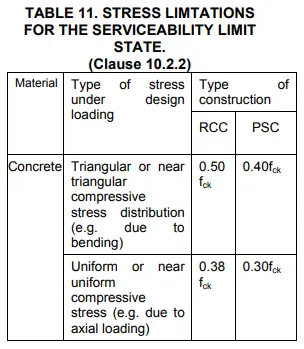
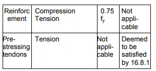
0.5fck and 0.38 fck clause for RCC: Due to triangular compressive stress distribution on account of bending, the average stress across the section is not uniform and hence there is some margin capacity left in the section. A value of 0.5fck is thus permitted in RCC for bending stress which is higher than 0.38fck allowed for direct compression which has rectangular stress distribution where margin capacity is not there.
0.4fck and 0.3fck clause for PSC: On similar grounds of compressive stress distribution, different permissble limits are there for compression by bending and direct compression in PSC beams also viz. 0.4fck and 0.3fck respectively.
Difference between RCC and PSC structures is that in RCC, the maximum design stresses are considered to be reached when the most critical load combination occurs which might be a rare occurrence during service. However in PSC, the maximum design stresses are considered to be reached when the girder is presstressed to its design value in casting yard itself. When live loads are actually applied in service, the stresses are relieved. Hence, higher permissible limits are given for RCC and tighter for PSC.
For reinforcement, permissible stress limit is 0.75fy where fy is yield stress of rebar in RCC and is calculated as per bending moment requirement.
For PSC beams, bending moments are taken directly by the prestressing strands and its stress limitations are as per clause 16.8.1
Ans 11
Crack width is nothing but the dimension of a structural crack in a reinforced concrete section subjected to tensile loads and exposed to different environmental conditions.
The requirement to restrict this crack width is:-
1. To prevent the reinforcement from getting exposed to external weather.
2. For serviceability such that it should not affect the durability.
3. Should not be visible to the eyes at it gives a bad idea about the structure.
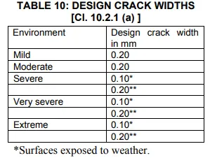

As per IRS CBC Code different allowable limits are given for crack width in conditions such as mild, moderate, severe, very severe and extreme. 0.2mm crack width is the maximum allowed as per table 10 of IRS CBC (Fig above)