Challenge 7
Ans 1
Pier caps are structural members of a bridge that transfer all the loads from the superstructure to the pier columns and foundation.
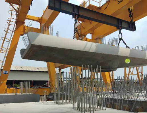
Operations in launching of pier cap:
Pier cap launching a process of erection of a precast pier cap on a constructed pier.
- The pier cap is transported from casting yard to the location of final erection.
- Then it is lifted by means of a crane or gantry (see figure above). During this operation a spreader beam may be used for transferring proper forces as desired by engineer.
- A central hole is usually left in the pier cap and reinforcement bars are left out of the cast pier.
- The pier cap is lowered by crane such that this central hole sits on the periphery of the rebars.
- The area around these rebars is then concreted to form a stitch joint connecting the pier and the pier cap.
Ans 2
Types of pier cap: RCC and Pre-stressed
Precast and cast in-situ.
|
Advantages & Disadvantages: |
|
|
Pre-stressed pier caps |
RCC Pier caps |
|
Slender and lighter section |
Thicker and heavier section |
|
Easier to lift |
Difficult to lift |
|
Aesthetic shapes due to moulds as required in yard |
Simple shapes - not so aesthetic |
|
No tension zone during service |
Always under tension during service |
|
Highly durable |
Less durable |
|
Faster construction since mostly precast |
Construction takes time since mostly cast in-situ |
|
Good quality control and finish |
Relatively less quality control |
|
Aesthetic shapes due to moulds as required in yard adding to city landscape |
Simple shapes - not so aesthetic |
|
Skilled specialized personnel required |
Requires less skilled manpower |
Thus, concluding from the above summary that pre-stressed precast pier caps are more viable than any other choice of pier cap.
Ans 3
Extract of Table 11 of IRS CBC for stress limitations in SLS for PSC & RCC pier caps (Cl 10.2.2)
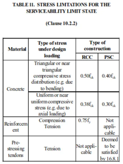
0.5fck and 0.38 fck clause for RCC: Due to triangular compressive stress distribution on account of bending, the average stress across the section is not uniform and hence there is some margin capacity left in the section. In other words, for bending, maximum stress is reached only at the extreme fibres. A value of 0.5fck is thus permitted in RCC for bending stress which is higher than 0.38fck allowed for direct compression which has rectangular stress distribution where margin capacity is not there. In other words, for direct compression, maximum stress is reached for the entire section.
0.4fck and 0.3fck clause for PSC: On similar grounds of direct and bending compressive stress distribution, different permissible limits are there in PSC beams also viz. 0.4fck and 0.3fck respectively.
Difference between RCC and PSC structures is that in RCC, the maximum design stresses are considered to be reached when the most critical load combination occurs which might be a rare occurrence during service. However, in PSC, the maximum design stresses are considered to be reached when the girder is prestressed to its design value in casting yard itself. Hence, higher permissible limits are given for RCC and tighter for PSC.
For reinforcement, permissible stress limit is 0.75fy where fy is yield stress of rebar in RCC and is calculated as per bending moment requirement.
For PSC beams, bending moments are taken directly by the prestressing strands and its stress limitations are as per clause 16.8.1.
Ans 4
Design crack width is nothing but the dimension of a structural crack in a reinforced concrete section subjected to tensile loads and exposed to different environmental conditions.
The requirement to restrict this crack width is:
- To prevent the reinforcement from getting exposed to external weather.
- For serviceability such that it should not affect the durability.
- Should not be visible to the eyes as it gives a bad idea about the structure.
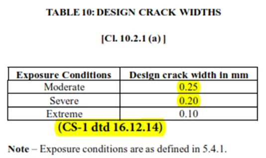
Clause 5.4.1
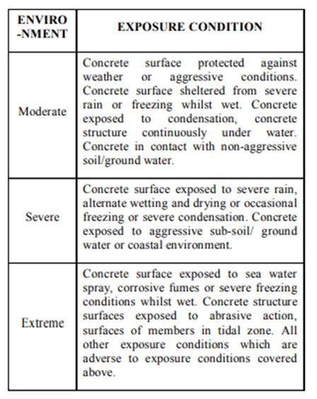
As per IRS CBC Code different allowable limits are given for crack width in conditions such as moderate, severe and extreme. 0.2mm crack width is the maximum allowed as per table 10 of IRS CBC.
Further the exposure conditions are given in Clause 5.4.1 as shown above, citing the city of Mumbai, we can refer to it as the extreme exposure condition as it experiences severe rain and is exposed to sea weather conditions.
Impact of design crack width is such that it will directly affect the design of all concrete sections i.e., it will affect the quantity of the bridge structure.
RCC structures are cracked sections below the neutral axis. The fixing of the values as stated in Table 11 is based on the fact that the crack should not create a discomfort for users on seeing it.
Ans 5
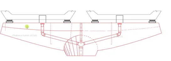
Functional requirement:
- To provide a firm base for resting of the superstructure bearings.
- Pier caps should be long enough to accommodate the bearings.
- To have sufficient gap outside the bearing pedestal, if shifting of pedestal is required as per construction tolerance.
Aesthetic requirement:
An elevated metro viaduct usually runs through the city’s main points. Thus, it provides a major aesthetic view to the city’s landscape. It is important that the viaduct’s structural components are engineered such that it provides a pleasant and good appearance to the surrounding.
Hence, we generally see that the shape of a pier is circular, the pier cap is a cantilever structure with curves around it and an aesthetically sound U-girder is preferred for design.
The shape of a pier cap beautifully blends with the superstructure and substructure.
Structural requirement:
- To allow the movement of traffic below the metro viaduct on either side of the pier
- To restrict the depth at the pier joint at junctions / locations where a clear distance from the ground level is a necessity as per DBR/GAD
Ans 6
Elements considered in finalizing the pier cap length:
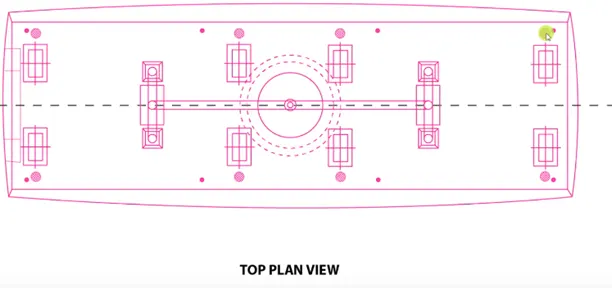
- Bearing pedestal dimensions in transverse direction and locations. For a U-trough girder these are directly under the locations of the vertical web at soffit slab junction.
- Outstand of the pedestals and pier cap in transverse direction (construction tolerance)
- Lifting hole locations (for precast pier caps)
- Locations and dimensions of jack in transverse direction for future bearing replacement
- Seating width of the U-girders from either span
- Drainage holes and pipes
Ans 7
Elements considered in designing the drainage of a pier cap:
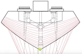
- Drainage locations viz. the U-girder discharging water and pier cap discharging water, if any.
Each U-girder has 2 drainage holes at either end. Thus, one at each pier resulting in 4 drainage holes on the pier cap for the girders. For pier caps, 2 drainage holes at centreline of pier. Thus, there will be 6 drainage holes on pier cap.
- Diameter of the drainage pipes as depending on the discharge of water.
- Shape of the drainage pipes taking the water to the pier and ground.
- Locations of the reinforcement bars and pre-stressed cables so that they do not hinder with the drainage pipes.
Ans 8
Elements considered in finalizing the width of a pier cap:
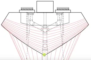
- Dimension of the pedestal (in longitudinal direction and its locations) seating U-girders from either span.
- Locations and dimensions of jack in longitudinal direction for future bearing replacement
- Outstand of the pedestals and pier cap in longitudinal direction (construction tolerance)
- Design size of the shear key placed between U-girders from either span.
- The design expansion gap between U-girders from either span.
Ans 9
Aesthetic requirement consideration of pier caps in elevated metro viaduct:
An elevated metro viaduct usually runs through the city’s main points. Thus, it provides a major aesthetic view to the city’s landscape. It is important that the viaduct’s structural components are engineered such that it provides a pleasant and good appearance to the surrounding.
Hence, we generally see that the shape of a pier is circular, the pier cap is a cantilever structure with curves around it and an aesthetically sound U-girder is preferred for design.
The shape of a pier cap beautifully blends with the superstructure and substructure.