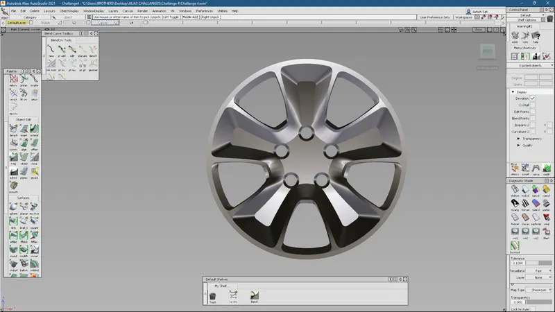
Challenge 4 : Concept Modelling of Alloy Wheel
Title Of The Project: Concept Modelling Of Alloy Wheel
Objective: To build surface for the given alloy wheel blueprint.

Introduction:
A surface, as the term is most generally used, is the outermost or uppermost layer of a physical object or space. It is the portion or region of the object that can first be perceived by an observer using the senses of sight and touch and is the portion with wich other materials first interact. Surface provides a geometrical description of the article boundary with none topoogies data.
Autodesk Alias (formerly known as Alias StudioTools) is a family of computer-aided industrial design (CAID) software predominantly used in automotive design and industrial design for generating class A surfaces using Bezier surface and non-uniform rational B-spline (NURBS) modeling method.
Design Approaches:
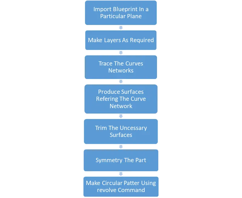
A flowchart of the design approaches is as shown below:
Description:
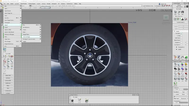
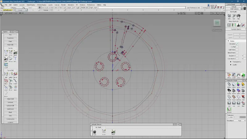
1. First of all, Import the blueprint as canvas image in a particular layout and scale it to adjust the size of the image to work comfortably as shown in the figure:
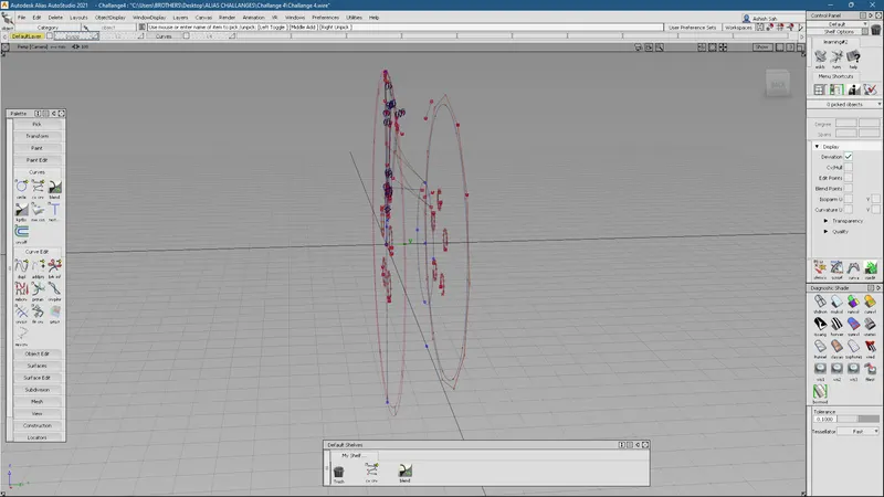
2. Since, we have only one view of the blueprint, we have to analyse the image to generate curves. Therefore, the curves are created by visualizing the other view and drawing it as shown in the figure. These images represents overall curve networks of the part.
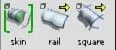
3. Surfaces are generated using Surface Tools surch as:
- skin: Creates a skin across multiple curves
- rail: Extrude profile freely or on path curves to make sweeping
- square: fill in the boundaries outline by connecting curves
-
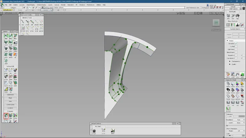
4. After creating these surfaces, they are aligned and the continuity is applited to the adjacent surfaces. The surfaces are aligned using the Align tool and the continuity is checked using srfcon under evaluate tab.


There are other several tools used such as attach, detach, duplicate, extent, planar, etc.
The following image shows the continuity of the surfaces:
5. Projecting Curves and Trimming:
In order to create some cut-outs on the surfaces as shown in the figure, first of all the curves are projected onto the surface and the unwanted surface is trimmed out using project tool and trim tool respectively.

In order to know the construction history, you can use the following tool:

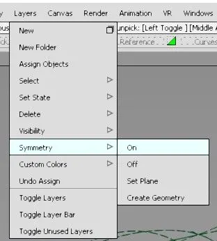
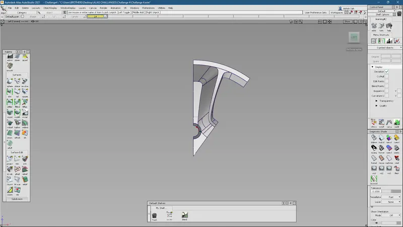
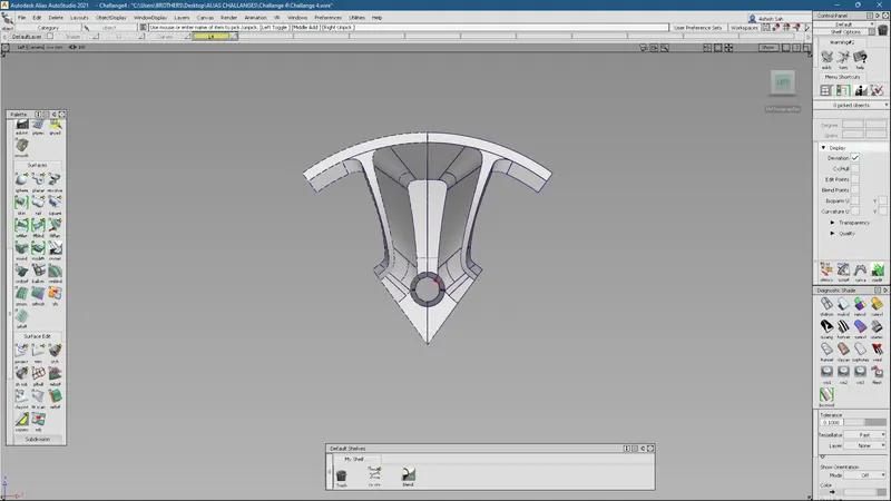
6. After creating the one half of the surfaces, we can create the other half by using the symmetry option in the layers feature.
Before Symmetry
After Symmetry
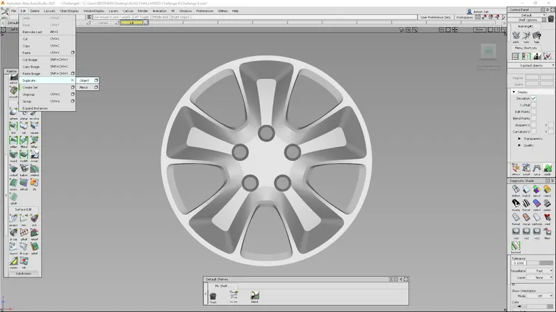
7. Finally, the part is revolved by going onto Edit>Duplicate>Object. A dialog box appears as shown:
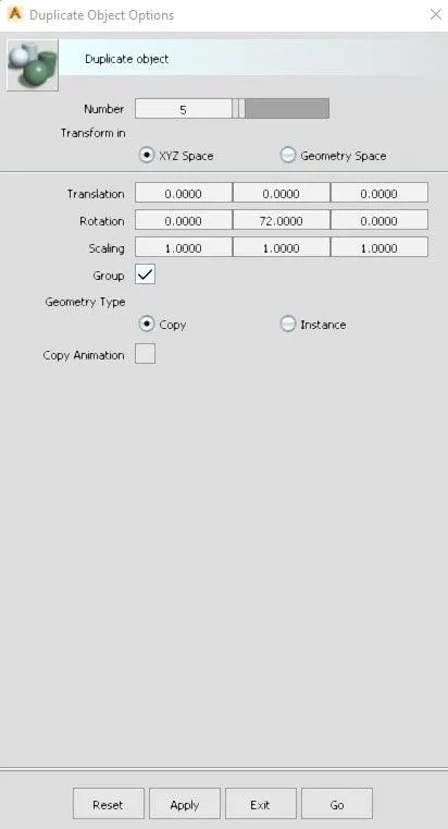
When we hit go after setting the values, the part will be formed as shown:
Conclusion:
Hence, the surfaces for the alloy wheel is built.
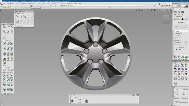
1. Left View
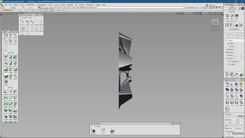
2. Back View
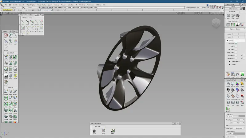
3. Isometric View
4. Right View