Challenge 4
Aim: Prepare a longitudinal model of I-girder and analyse for all the loads with following specifications.
Introduction:
Given Data of girder are
- Grillage model of 4 I-girders with span length of 27.0m.
- Having supports at 0.700m from both ends.
- Having following geometrical properties:
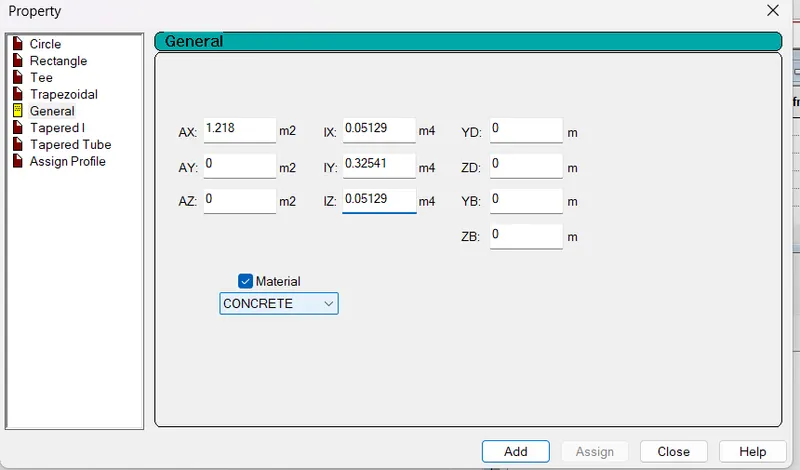
End Section: Area = 1.218m2
Iy = 0.32541m4
Iz = 0.05129m4
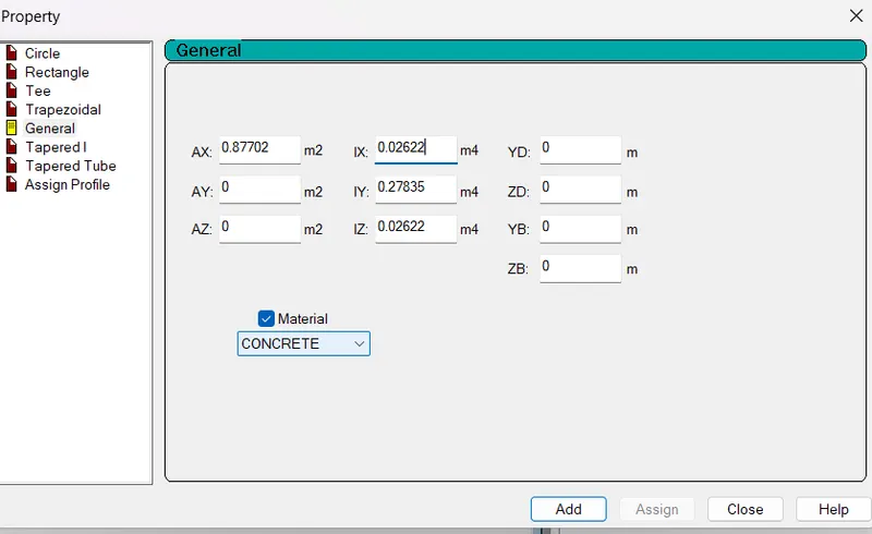
Mid Section: Area = 0.87702m2
Iy = 0.27835m4
Iz = 0.02622m4
4. Having material properties: Concrete, M60 grade
Other data's are assumed.
Procedure: Preparation of STAAD Model
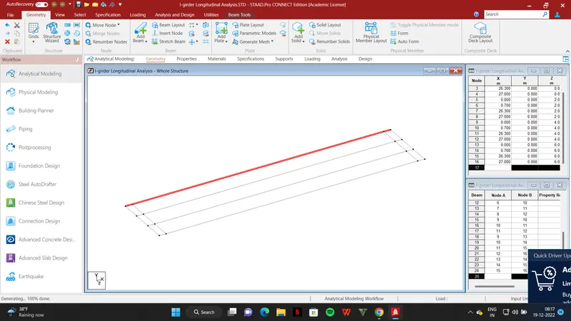
Step 1: Create Nodes with span length of 27m.
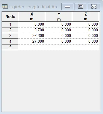
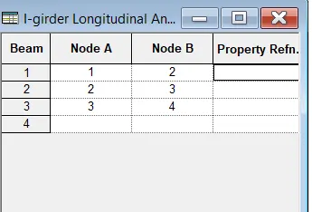
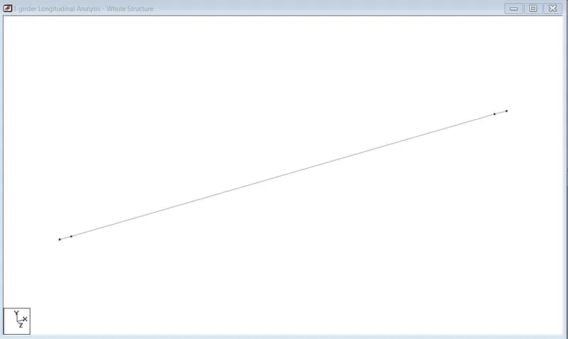
Step 2: Join the Nodes to create Beams:
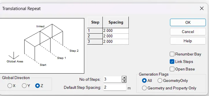
Step 3: To create 4 girders Translational Repeat is used in Z-direction with c/c spacing =2m
Step 4: Create internal diaphgrams at 2m distance in X-direction (assumed)
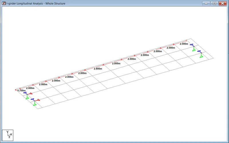
Step 5: Assign Supports:
i) Where all the moments are released
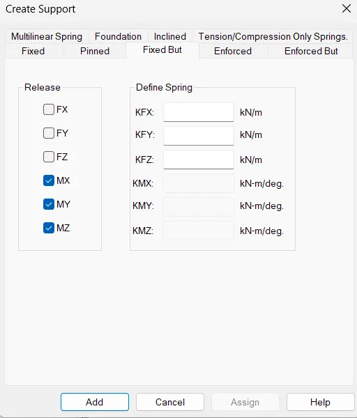
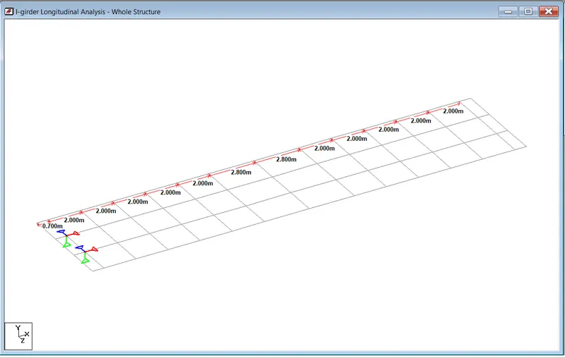
ii) To allow longitudinal movement we release FX in next support
iii) To allow transverse movement we release FZ
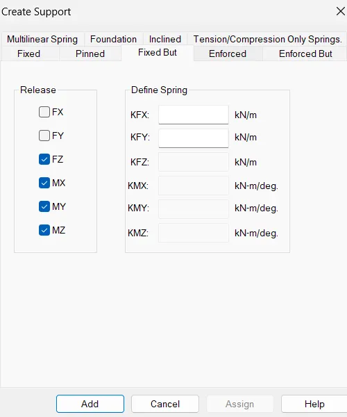
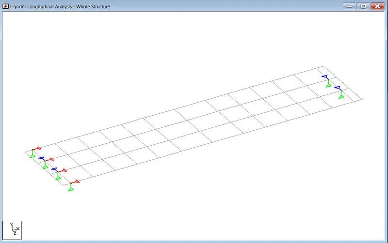
iv) We add roller support in X-Z plane
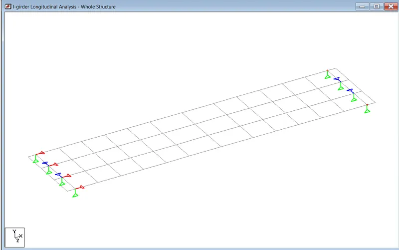
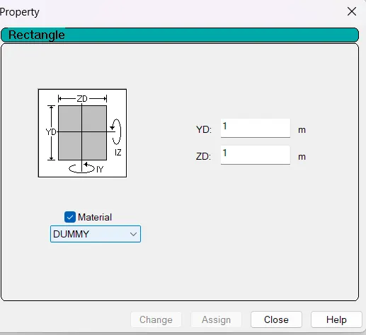
Step 6:Creating properties of girder and diaphgrams
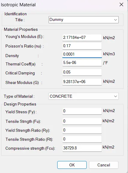
Concrete is M60 therefore Compressive strength = 5000fck^0.5= 5000(60)^0.5=38729.83MPa , For Diaphgram
Step 7: Define Sectional Properties for I-girder
i) End Section
ii) Mid Section
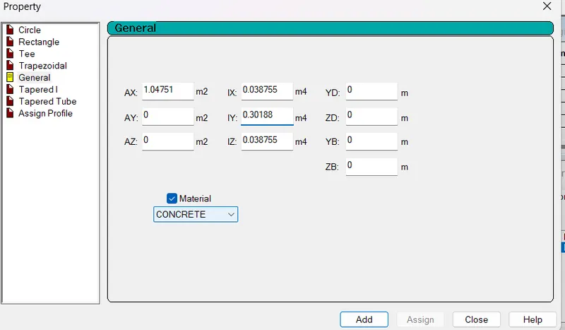
iii) Tapering Section between end & mid girder (Avg of both)
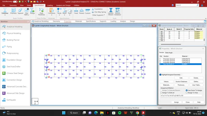
Step 8: For Assigning Loads-->
i) Deadload--> S/W -1
ii) SIDL-->
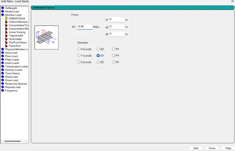
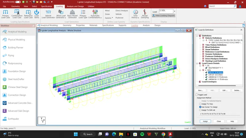
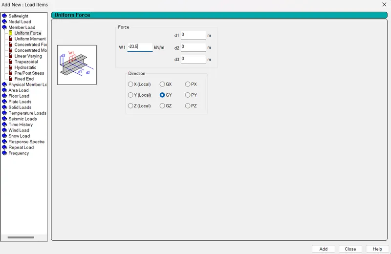
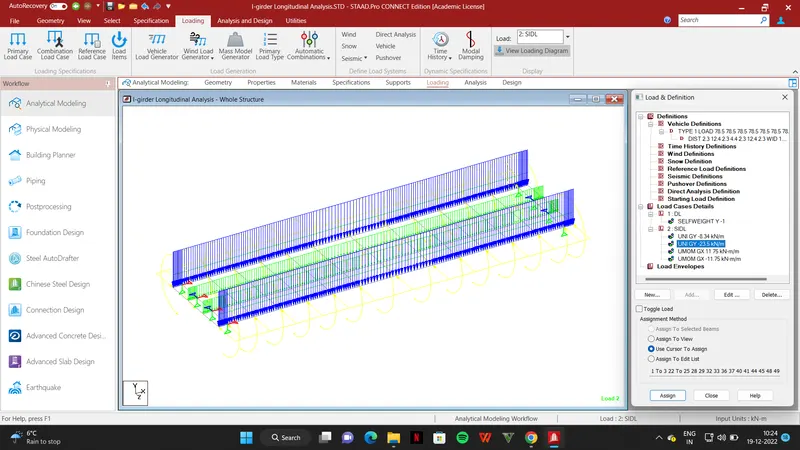
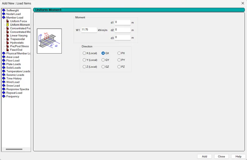
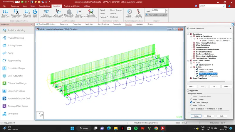
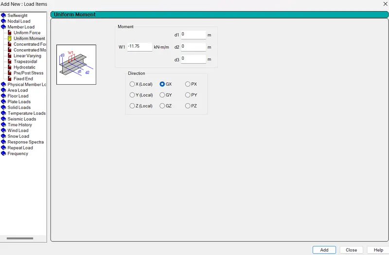
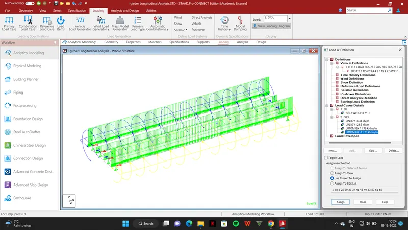
Step 9: Applying moving loads For LiveLoad
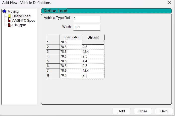
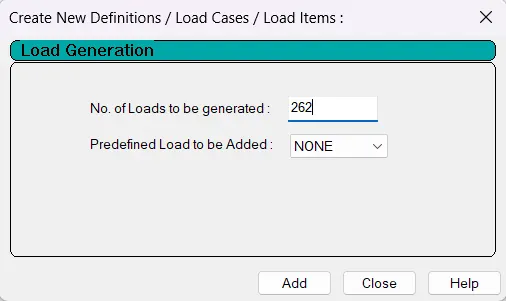
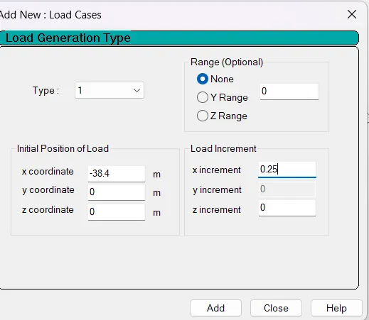
Now Run Analysis.
Results:
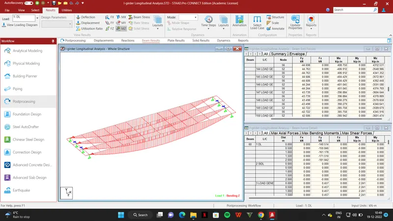
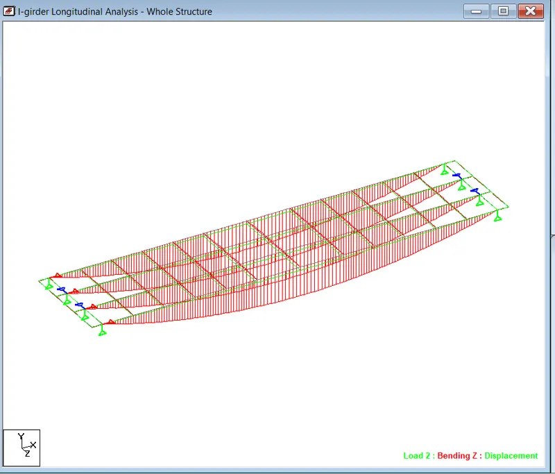
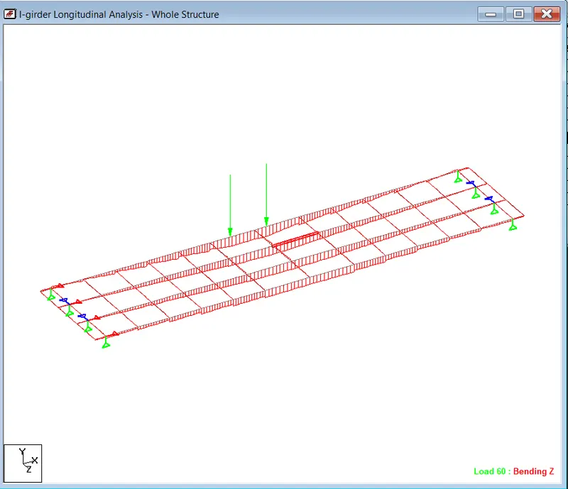
SLS LOAD COMBINATION = DL+1.2*SIDL+1.1*LL*I
I=Impact factor
Impact factor CDA as per IRS bridge rules will be 0.15+8/(6+L) = 0.15+8/(6+25.6) = 0.403.
Now this CDA is for broad guage as per IRS we have to calculate it for metro.
Speed for metro is 90km/hr whereas for Broadguage it is 116 km/hr
Therefore impact factor will be 0.403x(90/116)=0.313
Impact factor x Live load factor = 1.313 x 1.1 = 1.45 = factor for live load in SLS combination
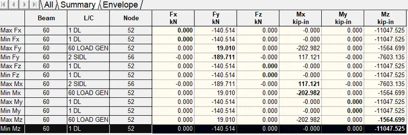
Moment = 11047.52+1.2*7603.13+1.45*1152 = 21841 kNm
This moment is used for design
Prestress design
No.of cables =4
No.of strands (n) = (7 strands in 3 cable + 8 strands in 1 cable)= 7*3+8=29
Prestressing force applied (P) = 0.765fpu x As x n x (1-loss) / 1000 kN
fpu = Nominal ultimate stress = 1860 MPa
Maximum jacking stress = 0.765 fpu = 0.765 x 1860 = 1422.9 MPa
As = Area of strand = 140mm2
Assume loss of 17.5%
Prestressing force (P) = 4766 kN
Stress @ bottom of girder = Compressive stress due to tendons - tensile stress due to external loading
= ( P/A + P.e/Z) - (M/Z)
Z = I/y = 1.24m3
A = Sectional Area of girder = 1.04 m2 (Average)
P = 4766 kN as calculated above
e = centre of gravity of girder section @ bottom of girder- centre of gravity of tendon @ bottom of girder = 0.454m
M = moment of SLS combination from longitudinal analysis for DL, SIDL & LL combination =21841 kNm
Therefore, Stress @ bottom of girder = 1.12 n/mm2 (Since the resultant stress is positive it is compressive, as to avoid tension we are providing tendons)