Challenge 5
Aim: Prepare and analyse a transverse model of Deck slab with following specifications
Given Data:
- Slab laid on top of 4 I-girders.
- Having supports spaced at 2.0m each.
- Having following geometrical properties:
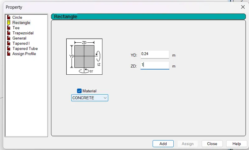
Thickness of slab = 0.240m
Width of slab = 1.0m
4. Having material properties: Concrete, M55 grade.
Procedure:
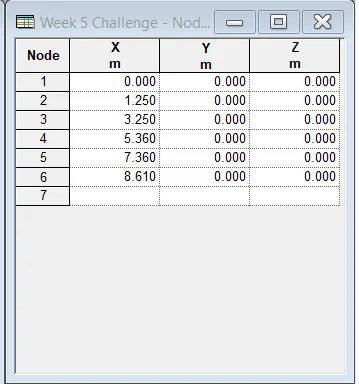
Step 1--> Creating Grid Modeling in STAAD.Pro.
Creating node (0,0,0) -> Create another node using coordinate X ( 1.250,3.250,3.250,7.250,8.50)
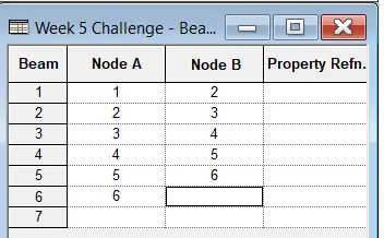
Now Add Beam using the beam tab.
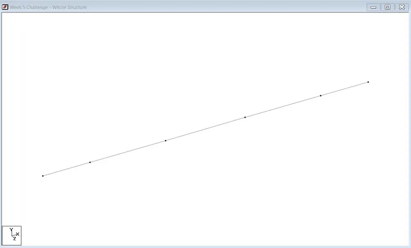
Step 2--> Assign Support
Specification -> Support -> Create -> Pinned -> Add -> Select support 2 -> Select node -> Assign to selected nodes -> Assign.
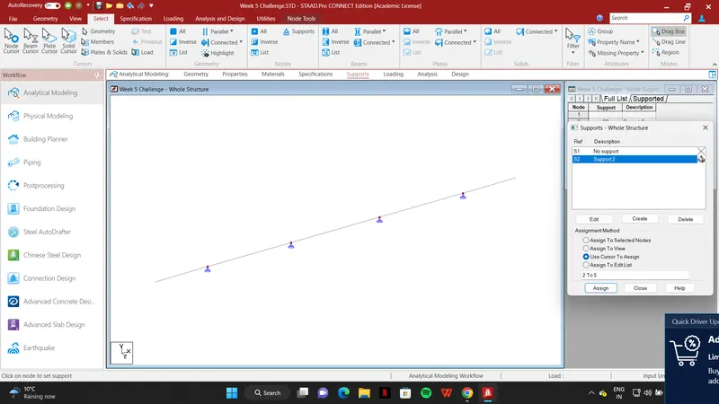
Step 3--> Assign Property to Model.
Specification -> Property -> Define -> Rectangle -> YD:0.24, ZD:1 -> Add -> Select the property -> Select the beam -> Assign to selected beam -> Assign.
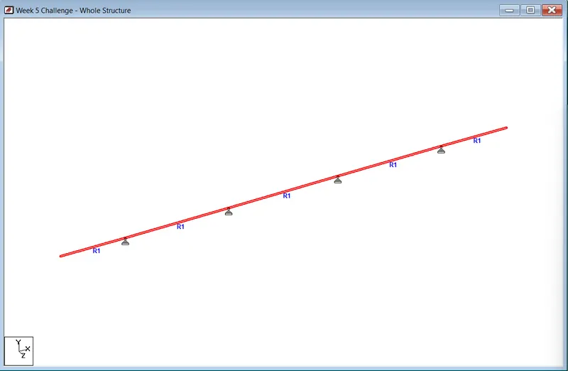
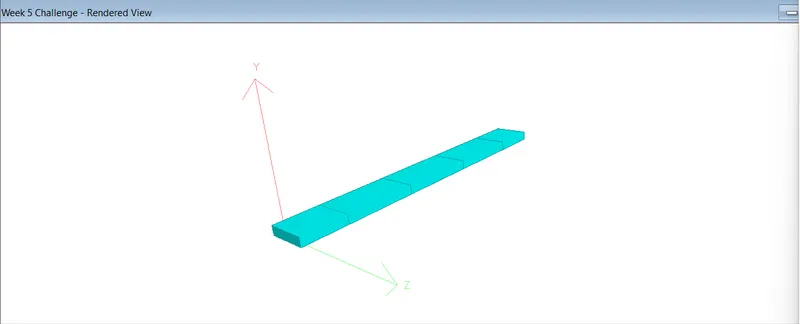
3D Model:
Step 4--> Applying Loading on Model
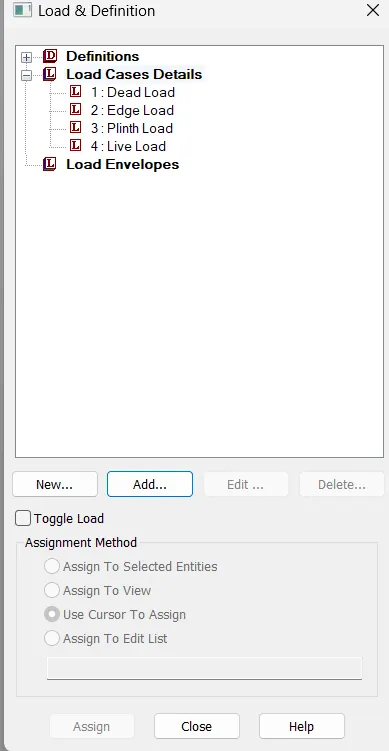
I. Dead Load.
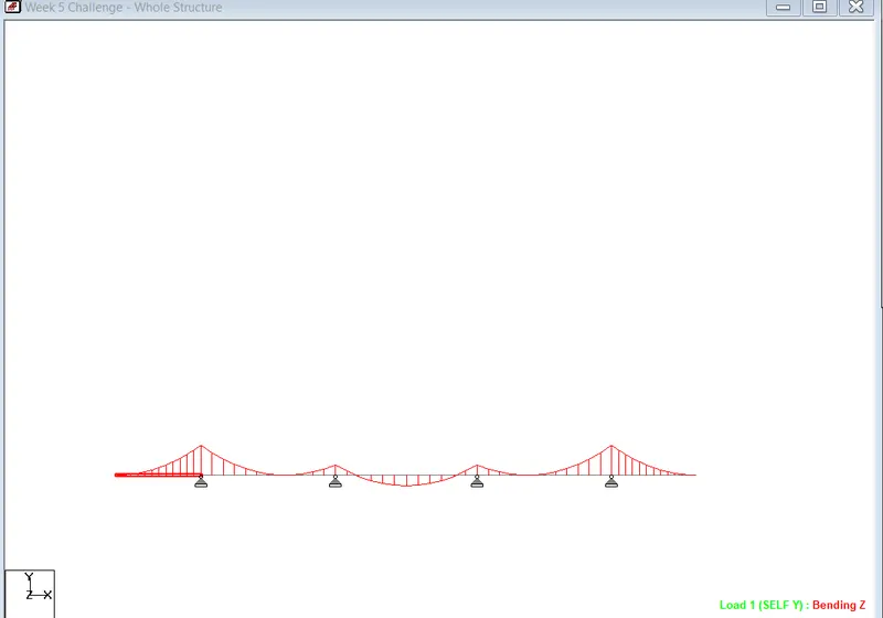
Loading -> Load & Defination -> Load Case Detail -> Tital ( Dead Load ) -> Add -> Select Dead Load -> Add -> Self Weight Factor -1 -> Add -> Select Selfweight - 1 -> Assign to view -> Assign.
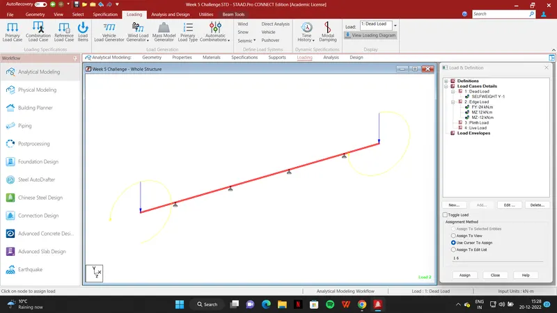
II. Edge Load.
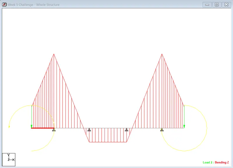
Loading -> Load & Definition -> Load Case Detail -> Title ( Edge Load) -> Add -> Select Edge Load -> Add -> Nodal Load -> Node -> Fy: -24 -> Add -> Select Load -> Selclect Node -> Assignto selected Node --> Assign
For the moment Mz: 12 and for another side Mz: -12.
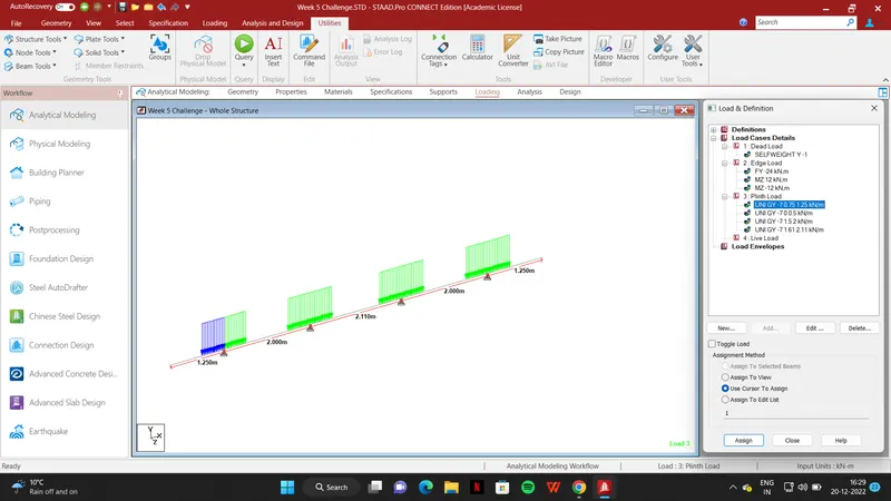
III. Plinth Load.
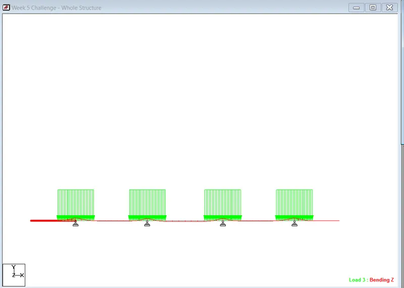
Loading -> Load & Definition -> Load Case Detail -> Title ( Plinth Load ) -> Add -> Select Plinth Load -> Add -> Member Load -> Uniform force (W: -7 , d1:0.75 , d2:1.25, GY) -> Add -> Select Load -> Select Suitable beam -> Assign to selected beam -> Assign.
For Different member beams according to suitable loads
Uniform force (W: -7 , d1:0 , d2:0.5, GY)
Uniform force (W: -7 , d1:1.5 , d2:0, GY)
Uniform force (W: -7 , d1:1.61, d2:2.11 GY)
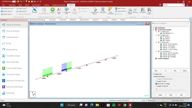
IV: Live Load (A).
Loading -> Load & Definition -> Load Case Detail -> Title ( Live Load LLA ) -> Add -> Select Live Load LLA -> Add -> Member Load -> Uniform force (W: -80 , d1:0.75 , d2:1.25, GY) -> Add -> Select Load -> Select Suitable beam -> Assign to selected beam -> Assign.
For Different member beams according to suitable loads
Uniform force (W: -80 , d1:0 , d2:0.5, GY)
Uniform force (W: -80 , d1:1.5 , d2: 2.0 GY).
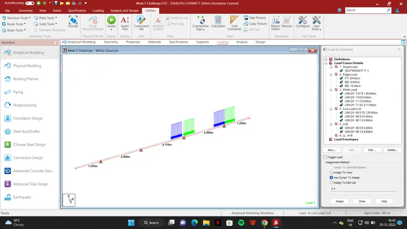
V: Live Load (B).
Loading -> Load & Definition -> Load Case Detail -> Title ( Live Load B ) -> Add -> Select Live Load B -> Add -> Member Load -> Uniform force (W: -80 , d1:1.5 , d2:2.0, GY) -> Add -> Select Load -> Select Suitable beam -> Assign to selected beam -> Assign.
For Different member beams according to suitable loads
Uniform force (W: -80 , d1:0 , d2:0.5, GY)
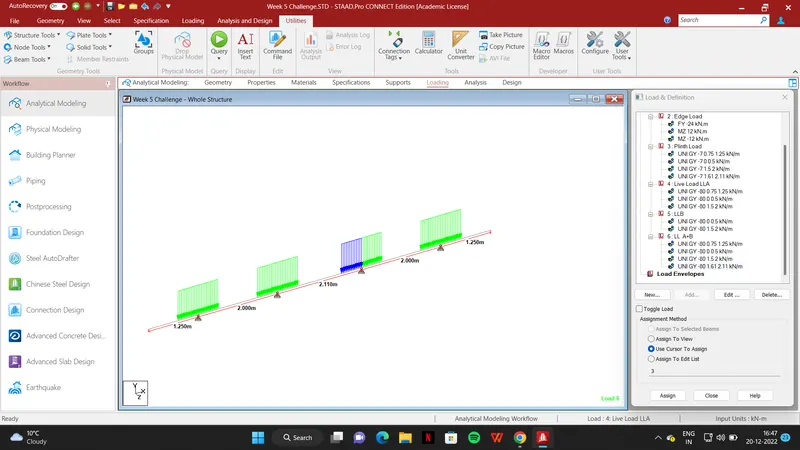
VI: Live Load (A + B).
Loading -> Load & Definition -> Load Case Detail -> Title ( Live Load A + B ) -> Add -> Select Live Load A + B -> Add -> Member Load -> Uniform force (W: -80 , d1:0.75 , d2:1.25, GY) -> Add -> Select Load -> Select Suitable beam -> Assign to selected beam -> Assign.
For Different member beams according to suitable loads
Uniform force (W: -80 , d1:0 , d2:0.5, GY)
Uniform force (W: -80 , d1:1.5 , d2:0, GY)
Uniform force (W: -80, d1:1.61 , d2: 2.11, GY)
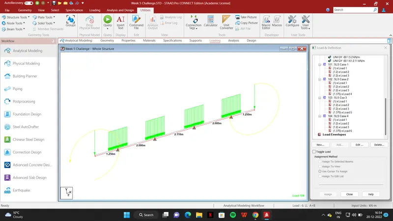
VII: SLS Load Combination.
Loading -> Load & Definition -> Load Case Detail -> Define combination -> Create title as SLS Case 1 -> Select Load -> Insert Factor -> Add.
- According to Loads create 4 Types of the case in SLS condition.
- All the Load factor is referred from Table 12 IRS CBC code.
- Impact factor is first calculated then add with Live Load factor which is given in the code.
VIII: ULS Load Combination.
Loading -> Load & Definition -> Load Case Detail -> Define combination -> Create title as ULS Case 1 -> Select Load -> Insert Factor -> Add.
- According to Loads create 4 Types of cases in SLS condition.
- All the Load factor is referred from Table 12 IRS CBC code
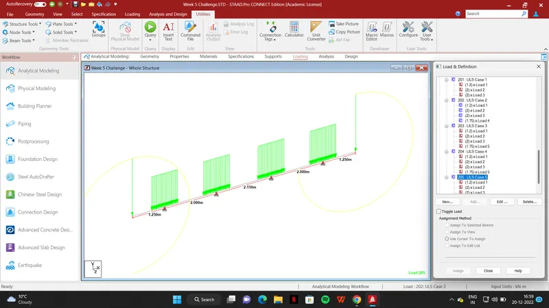
Step 5--> Analysis And Result
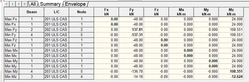
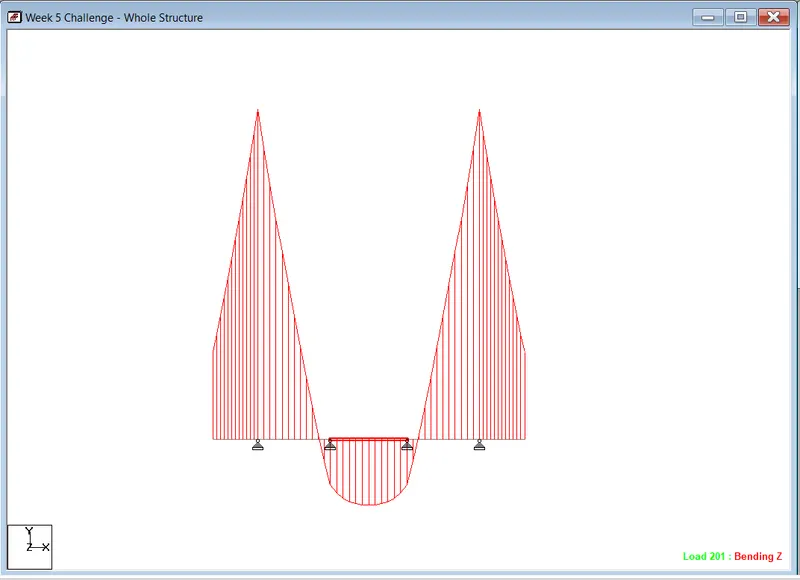
Analysis And Design -> Analysis Commands -> Run Analysis -> Go to post-processing mode -> Done
1. DeadLoad
2. Edge Load
3. Plinth Load
4. Live Load
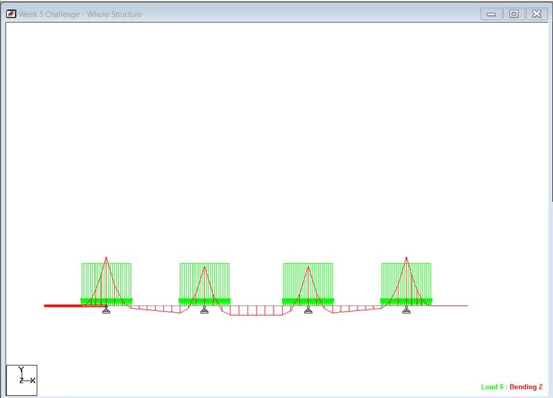
5. Maxm. SLS Case
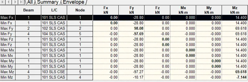
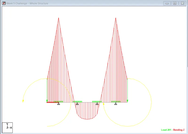
6. Maxm ULS Case