Challenge 10
Ans 1
The pile caps need to be designed for certain allowable pile eccentricity such that construction tolerances of the piles are accounted for. In other words, If the piles are constructed with certain tilt and / or shift, which is a possibility due to pile driving errors, then pile cap compensates for that by allowing the pier to be kept as per theory.
The pile cap must be designed for these additional shears and moments with that eccentricity of pier.
Advantages of pile cap with respect to tilt and shift of piles:
- Pile caps provide flexibility in construction. For instance, if the pier is to be placed directly on piles and say that piles are constructed with a certain allowable eccentricity, then the pier would also be constructed with that eccentricity.
- This means that the pier cap and bearings shall also be constructed eccentric and in the end the superstructure alignment would not be where we intend it to be.
- For this purpose, pile caps are designed, and they provide a firm base such that the piers can be constructed at their exact location.
- Normally, a pile cap covers the entire area of the group of piles and 150 mm offset beyond it and the plan dimensions are decided accordingly. This is to cater to any minor tilt or shift during the casting of the pile.
- Moreover, pile caps provide a firm base and a firm working platform for the construction activities of the bridge like pier, pier cap and superstructure. The formwork arrangement can be easily accommodated on this sufficiently large base.
Ans 2
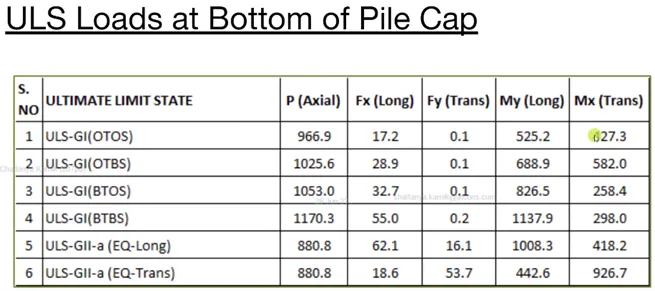
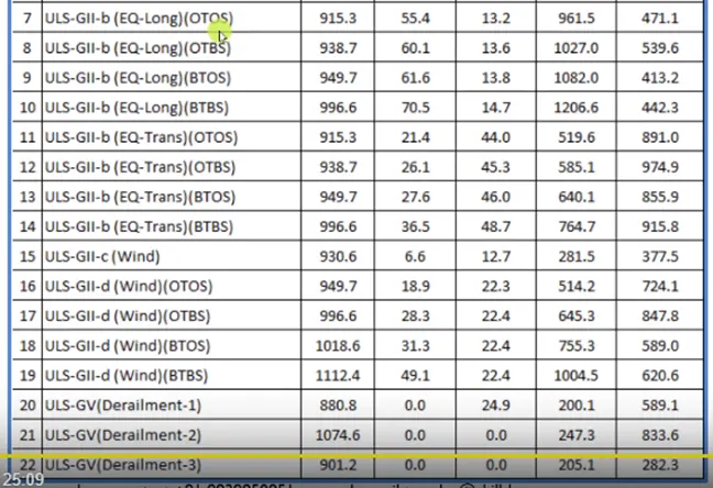
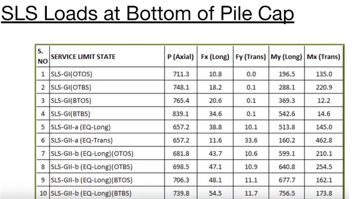
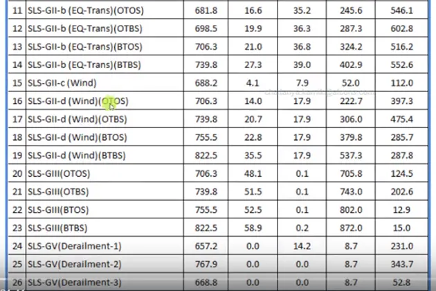
Following table shows the various load combinations at the bottom of pile cap that are to be considered while designing:
Ans 3
Considering load combinations as described in answer no. 2, following is the holistic idea envisaged in design of pile cap:
Maximum and minimum working loads:
For the SLS load case, 4 cases are used for live loads considering OTOS, OTBS, BTOS and BTBS cases. Out of this minimum case of working load is OTOS and the maximum case is BTBS. Loads are shown below, both individual and SLS combination.
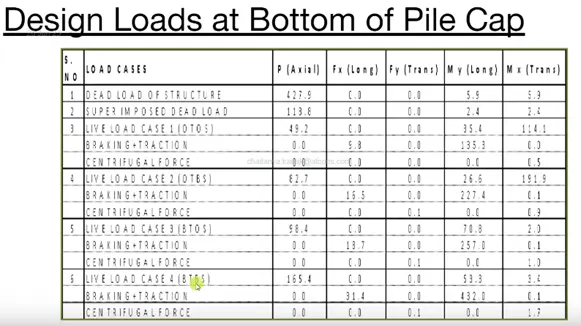
Maximum BTBS, P (Axial) = 165.4
Minimum OTOS, P (Axial) = 49.2
Maximum SLS BTBS, P (Axial) = 839.1
Minimum SLS OTOS, P (Axial) = 711.3
RIVET THEORY:
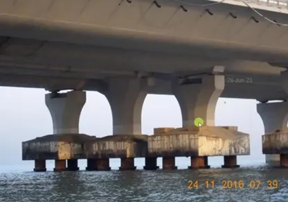
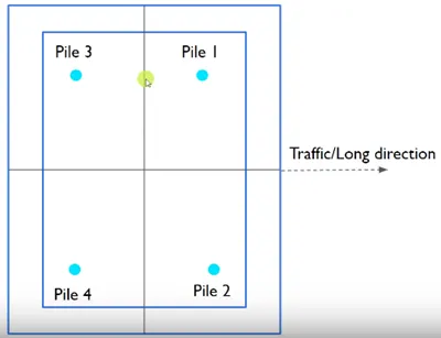
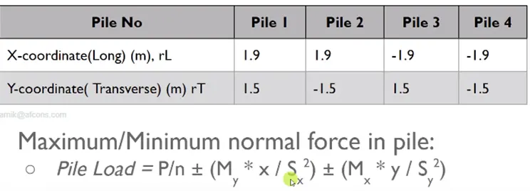
In rivet theory of designing a pile cap, we consider a group of piles (like a group of rivets in connections) for resisting moments, shear and axial loads. The formula for the rivet theory is shown in figure above this para.
Assuming 4 piles in plan as shown above spaced at 3.8 m in long direction and 3.0 m in transverse direction, a longitudinal & transverse moment at base of pier cap will have a load in the pile as per rivet theory such that it is a product of moment and farthest lever arm divided by summation of the distances in the perpendicular direction. If My is the moment, Σ x2 has to be used and vice versa.
For example, a OTOS case with train loaded on track over ‘Pile 1’ causes longitudinal and transverse moment such that there is maximum compressive load on ‘Pile 1’ and maximum tensile load on ‘Pile 4’.
For pile cap design, this compression load per pile as calculated above can be treated as an upward force on the pile cap. The upward force in turn will cause a cantilever moment and a shear force on the pile cap at the face of the pier for which it must be designed.
Stress check:
After obtaining values for maximum shear and bending forces on pile cap, we proceed for the design of pile cap wherein standard section check software can be used.
Another option is designing it by first principle. We first locate the neutral axis of the section by equating the concrete compression forces to the steel tensile forces.
Moment of resistance of the tension zone is given by Mud = 0.87*fy*Ast*(d-0.42Xu)
Moment of resistance of the compression zone is given by Mud = 0.36*fck*b*Xu*(d-0.42Xu)
Mud minimum of above is the capacity of the section and should be greater than applied design moments.
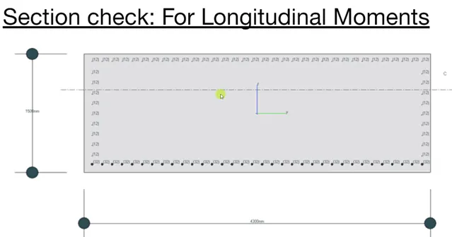
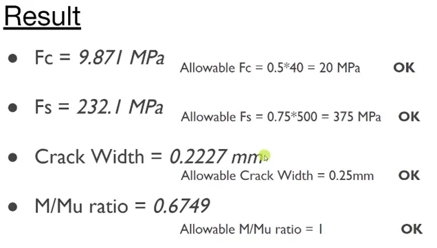
Crack width is calculated with the help of standard set of formula and checked as per relevant codes.
Based on the stresses in concrete Fc, stresses in steel Fy, crack width limit and M/Mu ratio, a design engineer can optimize the depth/reinforcement/spacing of rebars and recheck the values with new iterations so that a most optimized section is obtained.
Ans 4
Reinforcement calculation for piles:
Firstly, we need to find the bending moment in the pile based on pile modelling with maximum compressive load applied at the top and soil springs modelled from the ground level to the pile cut off level.
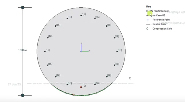
Then we should apply a unit load at the top of the pile (pile cap level) to understand the moments generated in the pile. Now, if we know the actual horizontal load on each pile (Total H / nos.) then we can get the actual bending moments on the pile by multiplying moments obtained from unit load theory by (H/n).
Going by first principle, the factored moments obtained from above iteration are then used to get the reinforcement required in a pile. Reinforcement can be provided as single layer circular or double layer bundled bars for very high moments. Reinforcement curtailment can be done for sections with reduced bending moments i.e. start of curtailment shall be from 2d of the actual section.
Locate the neutral axis Xu by equating compressive stress with tensile stress.
Moment of resistance of the tension zone is given by Mud = 0.87*fy*Ast*(d-0.42Xu)
CODAL REQUIREMENT OF REINFORCEMENT IN PILE: Minimum reinforcement in piles = 0.4 % of gross cross-sectional area.
Important: Higher clear cover of about 75 mm is required in piles since the pile is completely buried in soil and corrosion of rebar cannot be repaired at all.
Crack width for piles:
Crack width is calculated with the help of standard set of formula and checked as per relevant codes.
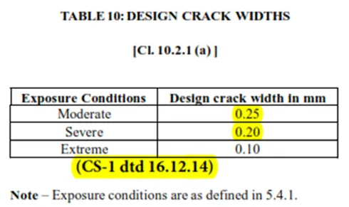
Clause 5.4.1
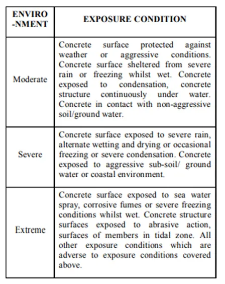
As per IRS CBC Code different allowable limits are given for crack width in conditions such as moderate, severe and extreme. 0.2mm crack width is the maximum allowed as per table 10 of IRS CBC.
Crack width can be calculated from any available standard software in the organization or by standard empirical formula mentioned in code for RCC section and can be compared with the allowable crack width.
Based on the stresses in concrete Fc, stresses in steel Fy, crack width limit and M/Mu ratio, a design engineer can optimize the reinforcement/spacing of rebars and recheck the values with new iterations so that a most optimized section is obtained. However, all this is restricted to a minimum reinforcement of 0.4% of the gross cross-sectional area.
Ans 5
PILE FOUNDATION:
It is a type of deep foundation adopted for ground where the soil is considered weak. Pile foundation is provided where we do not get good bearing capacity at a shallow depth from the ground level. In other words, if the soil strata fails to provide the required bearing capacity for the loads coming on top of it from the bridge, then we go for a pile foundation to transfer the loads to the ground. The design of piles in pile foundation is based on structural as well as geotechnical capacities of the pile.
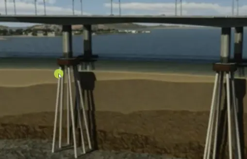
SIGNIFICANCE OF PILE CAPS
Significance of the pile cap: (STRUCTURAL)
- Transferring all the loads from the piers to the piles
- Converting the various forms of loads like moments (longitudinal and transverse, bi-directional shear and vertical loads and transferring it to the piles in the form of tension and compression
- To carry out the above load transfer, it must be a rigid structure.
- If seabed is too deep for about 30.0 m from top of pile or if sea bed has a rocky strata, we can get advantages out of monopile.
Significance of the pile cap: (FUNCTIONAL)
- Pile caps provide flexibility in construction. For instance, if the pier is to be placed directly on piles and say that piles are constructed with a certain allowable eccentricity, then the pier would also be constructed with that eccentricity.
- This means that the pier cap and bearings shall also be constructed eccentric and in the end the superstructure alignment would not be where we intend it to be.
- For this purpose, pile caps are designed, and they provide a firm base such that the piers can be constructed at their exact location.
- Normally, a pile cap covers the entire area of the group of piles and 150 mm offset beyond it and the plan dimensions are decided accordingly. This is to cater to any minor tilt or shift during the casting of the pile.
- Moreover, pile caps provide a firm base and a firm working platform for the construction activities of the bridge like pier, pier cap and superstructure. The formwork arrangement can be easily accommodated on this sufficiently large base.
TYPES OF PILE FOUNDATION:
Based on structural arrangement:
- Group piles
- Monopiles
Based on design philosophy:
- Friction piles
- End bearing piles
Based on construction:
- Bored cast in-situ piles
- Driven piles
Ans 6
Monopiles: A single pile on which the pier is constructed directly without the need to design a pile cap.
|
Advantages & Disadvantages of Monopiles |
|
|
Fast construction of single pile |
Construction errors like tilt in pile cannot be adjusted |
|
Construction of multiple piles can be avoided |
Pier must be shifted to be aligned with the pile |
|
Pile cap construction activity removed |
Load flow from pier to pile is by shear and flexure |
|
Accurate construction required with less margins |
|
|
More material required due to larger diameter pile |
|
|
Special equipment required for construction of larger diameter pile need to be deployed |
|
|
Skilled personnel required for construction of monopile |
|
Hence, we can conclude that monopiles are preferred where considerable savings of time in the construction of pile foundations for the entire project are foreseen. It is important to note that the special equipment and manpower to be used for this activity and any additional quantity required is largely compensated by savings in project duration.
Ans 7
Orientation of piles:
- Orientation of piles in multiple pile group is kept eccentric with respect to the pier to cater permanent differential moments.
- It could be said that this effect is taken to reduce the overall push/pull effects on the individual piles by matching the CG of forces with CG of piles.
- The structural placement of the piles is decided such that the group of piles is most stable. The CG of the group of piles can be shifted by the eccentricity which is equal to the difference between the moments on the LHS / RHS side.
- Piles must be socketed properly in rocky strata since load transfer is by end bearing. This socketing length must be sufficient so that crushing of pile bottom is prevented. Socket is a groove provided in the rock of ~ 2d to 4d and if we can reduce the load in this area by even small amount, it is a huge saving in overall material of the bridge.
- The centre-to-centre distance between piles ranges from 2d to 4d. This minimum requirement is so that the dispersed friction on soil around any pile does not hinder with the other.
- Also, if there are any existing underground utilities, we can adjust the orientation of the piles such that they are within these limits and are clear of all obstructions beneath.
- For instance, we have the overall load at a particular pier location. Based on the geotechnical data (borelog) available for that pier, we can get the vertical load carrying capacity of a single pile. With some preliminary calculations of horizontal loads and moments adding to the pile, say we get a 5 pile group as the most efficient load carrying structure, then we must orient it in such a way that the least axial forces are acting on individual piles.
- This can be achieved by adjusting the pentagonal shape of the piles and pile cap and/or by bodily shifting the group of piles as mentioned in above points.