Centrifugal pump design and analysis
Centrifugal pump design and analysis
Aim:To create a Centrifugal Pump andObtain the relationship between Pressure Ratio and Mass Flow Rate.
Introduction:
Centrifugal pumps are used to transport fluids by the conversion of rotational kinetic energy to the hydrodynamic energy of the fluid flow. The rotational energy typically comes from an engine or electric motor.The fluid enters the pump impeller along or near to the rotating axis and is accelerated by the impeller, flowing radially outward into a diffuser or volute chamber (casing), from which it exits.
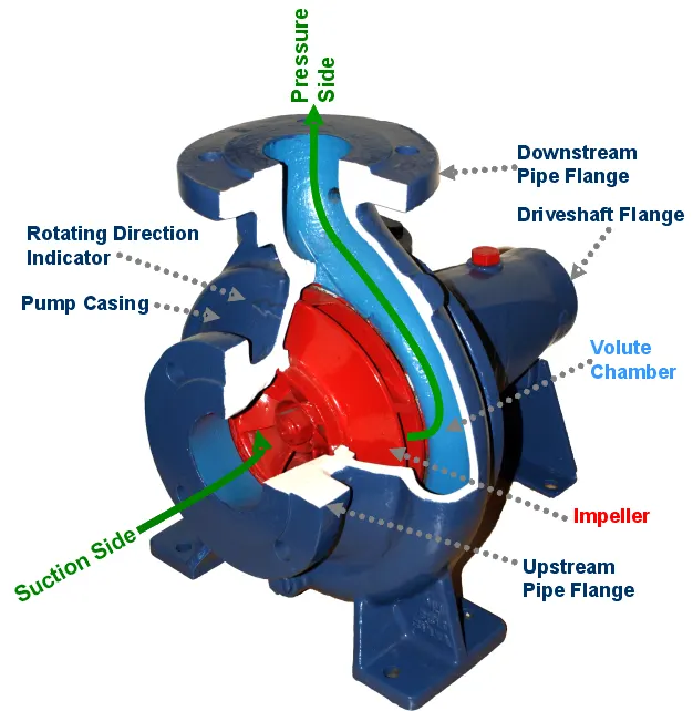
Working:
Like most pumps, a centrifugal pump converts rotational energy, often from a motor, to energy in a moving fluid. A portion of the energy goes into kinetic energy of the fluid. Fluid enters axially through eye of the casing, is caught up in the impeller blades, and is whirled tangentially and radially outward until it leaves through all circumferential parts of the impeller into the diffuser part of the casing. The fluid gains both velocity and pressure while passing through the impeller. The doughnut-shaped diffuser, or scroll, section of the casing decelerates the flow and further increases the pressure.
Applications:
Common uses include water, sewage, agriculture, petroleum and petrochemical pumping. Centrifugal pumps are often chosen for their high flow rate capabilities, abrasive solution compatibility, mixing potential, as well as their relatively simple engineering.A centrifugal fan is commonly used to implement a vaccum cleaner. The reverse function of the centrifugal pump is a water turbine converting potential energy of water pressure into mechanical rotational energy.
Procedure:
Step 1:Select Top Plane ->Sketch -> Draw a circle of radius 0.04m and with a same centre draw an other circle of 0.08m.
Step 2:Select Arc Tool and draw arcs (blades i.e two arcs drawing near).Trim the outer circle except the part of arcs.Then select linear sketch pattern -> circular pattern the select the blades drawn with the help of arc and give the number of blades needed i.e 5 or 6 or even more.Trim the extra section which is between the inner circle and blades.Then extrude it with selecting mid plane to 0.01m.Impeller is done.
Step 4: Again sketch on top plane and draw a circle of radius 0.085m with the same centre and extrude it by selecting mid plane to 0.015m and while extruding dont select merge results.Volute is done.
Step 5: Again sketch on Top plane and with the same centre of previous circle draw a circle of radius 0.015m and extrude it to 7 to 8 cm .Inlet runner is ready.
Step 6: Sketch on top palne select centre line tool and draw a tangent to outer circle in such a way i.e the cente of circle is perpendicular to the tangent.Then with the help of line tool draw a line parallel to the tangent of same dimension and exit sketch.Go to features and with the help of refrence geometry creat a plane on that lines and draw a circle on that plane and with the help os sweeep tool the outlet runner is ready.
Step 7: Now combine the geometry .Create shell for inlet runner and outlet runner of thicknes of 0.002m.
Step 8: Draw a circle with the same centre in such a way that should be bigger than impeller but smaller than casing(i.e should not inresect with casing).Extrude it with mid plane to the length of impeller.
Step 9: Create Lids for both inlet runner and outlet runner.The Geometry of Centrifugal Pump is done.Save the file.
Step 10: Open flow simulation wizard and give the project name and select internal flow and select rotation and select local region (averaging).Select water as fluid and select finish.
Step 11: Now there are some parts in solid which shouldn't interfere in geometry so from component control in input data dont select the circle drawn inside(i.e the circle bigger than impeller and smaller than casing)and click ok.
Step 12: Select the rotating region and give 1500 rad/sec as rpm.
Step 13: Insert Boundary conditions .At inlet give environmental pressure as 1 bar and at outlet give outlet velocity as 10m/s.
Step 14:Give surface goals .At inlet and outlet give total average pressure and give mass flow rate at outlet.and with the help of equation goals give pressure ratio.And in global mesh select advanced channel refinement.
Step 15: Now in calculation control select only iterations and give number of iterations. Run the simulation.
Step 16:After the simulation insert cut plots and flow trajectories.
Step 17:Open new parametric study and give input variable as output velocity and give range with numbers for calculation.And in output variable select all goals and cut plots and run the simulation.
Results:
For baseline simulation:
Velocity:
Pressure:
For velocity=10m/s :
velocity:
The velocity is more near blades as shown in cut plot and less near the outlet runner.And in flow trajectory the velocity is less in inlet and outlet runner but more in the volute .
Pressure:
The pressure is more near the outlet and moderate near the blades inside the volute.In flow trajectory we can obseve that the pressure is less in inlet runner but more in the outlet runner.
For velocity =15m/s
Velocity:
The velocity is more near blades as shown in cut plot and less near the outlet runner but better than the previous plot.And in flow trajectory the velocity is less in inlet and outlet runner but more in the volute .
Pressure:
The pressure is more in outlet runner than inside the volute.In flow trajectory the pressure is less in inlet runner but goes on increasing and its more near the outlet runner.
For velocity=20m/s:
Velocity:
The velocity is more near blades and less near the outlet runner but better than previous plot. in flow trajectory the velocity is less near inlet and outlet runner but more inside volute.
Pressure:
The pressure is less in volute compared to outlet runner as it is more there.In flow trajectory we can see that the pressure is less in the inlet runner but goes on increasing and is more near the outlet runner.
For velocity=25m/s:
Velocity:
The velocity is more near the blades and goes in decresing from the ends of impeller to outlet runner and is minimum in outlet runner.In flow trajectory the velocity is less in the inlet and outlet but moderate in the volute.
Pressure:
The pressure goes on incresing slowly from impeller to outlet runner.In flow trajectory the pressure is less in inlet runner and goes on increasing and its maximum at the outlet runner.
For velocity=30 m/s:
Velocity:
The velocity is more near the blades and moderate near the impeller and then goes on decreasing and minimum near the outlet runner.In flow trajectory the velocity is less in inlet and outlet runner and more in the volute.
Pressure:
The Pressure is less near the impeller and goes on increasing near the outlet runner.In flow trajectory the pressure is less in inlet runner and maximum near the outlet runner.
Mass flow rate v/s Pressure Ratio:
Velocity v/s Mass flow rate:
Velocity v/s Pressure Ratio:
Observation and Conclusion:
1)In velocity plots the velocity was high near the blades but less in inlet and outlet runner.
2)In pressure plots the pressure was maximum at outlet but less in inlet runner.
By the graph plots :-
1)In velocity v/s mass flow rate plot as the velocity increses uniformily the mass flow rate goes on decreasing uniformily
2)in velocity v/s pressure ratio plot as velocity increases the pressure ratio also increases.
So as mass flow rate decreases pressure ratio increases.
Refrences:
->Wikipedia.