Car BIW roof crash analysis (rollover) under FMVSS 214using Hypermesh and Radioss by Altair.
OBJECTIVE: To test, understand and validate the crashworthiness of Roof crush (which will have the same impact as a rollover) of Dodge Neon BIW Model under FMVSS 216 standards using Radioss in Hypermesh.
ABSTRACT:
FMVSS 216, Roof Crush Resistance, establishes strength requirements for the passenger compartment roof of passenger cars, multipurpose passenger vehicles, trucks, and buses with a GVWR of 2722 kilograms or less. The purpose of the standard is to reduce deaths and injuries due to the crushing of the roof into the passenger compartment in rollover accidents
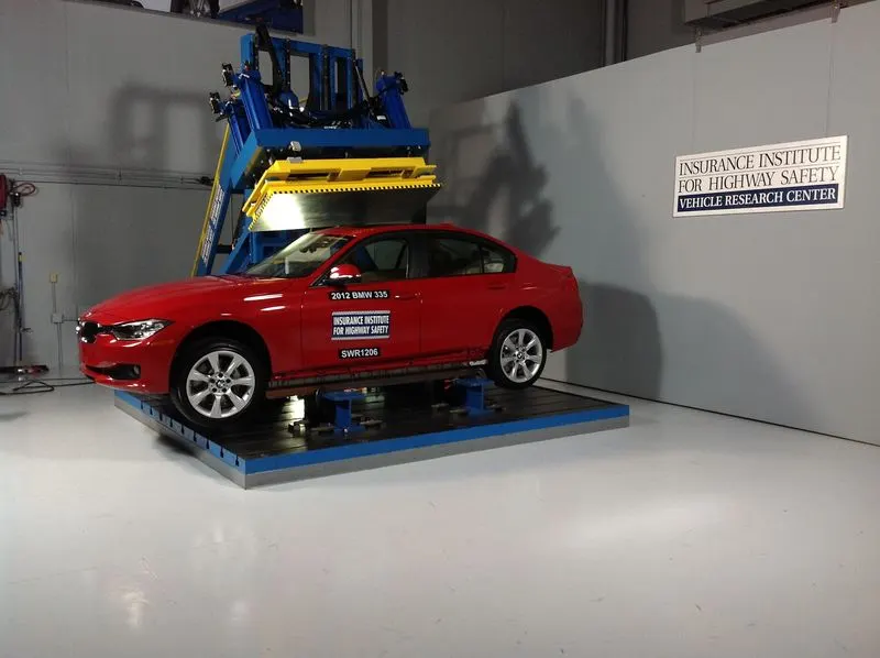
The prescribed static loading device is a rigid unyielding rectangular block 762 millimeters by 1,829 millimeters. It shall not move more than 127 millimeters to achieve the specified resistive load when applied to the forward edge of a vehicle’s roof
Roof Crush Resistance establishes strength requirements for the
passenger compartment roof of passenger cars, multipurpose passenger vehicles,
trucks and buses with a GVWR of 2722 kilograms or less
The resistive load to be achieved is 1½ times the unloaded vehicle weight (UVW) of the test vehicle or 22,240 Newtons, whichever is less. Both the left and right front portions of the vehicle's roof structure shall be capable of meeting the requirements. The passenger car's sills shall be placed on a rigid horizontal surface and fixed rigidly in position. The vehicle's windows shall be closed and the doors shall be locked.
Use the plot of force vs. displacement to directly obtain the following information:
The distance of loading device travel at which the minimum required roof crush resistance was reached.
If minimum roof crush resistance was not reached, provide the maximum roof crush resistance obtained and the distance of the static loading device traveled when it was obtained.
In order to represent hydraulic machine is used with steel plate to push it into car roof with rocker locked in position.

Quasi-static Analysis :
Static analysis is when the load does not vary with respect to time. Dynamic analysis is when the load with respect to time and inertia plays an important role.
Quasi-Static, quasi-equilibrium, from the Latin quasi, meaning 'as if' and static means stable. So in this case the load varies with time but it is so small which is negligible. When the body is loaded slowly its deformation rate is also very slow.
(Since due to limitation of 100k nodes in Student edition calculation is done on BIW model till B-pillar with 99084 nodes in total.)
ANALYSIS SETUP:
1. Import
• Car
• Impactor
2. Transforms
- A translation to put point A at global ( -3500.00, 584.822, 1343.06)
- Create a node with the coordinates given above.
- Measure the distance between point A and newly created node. Which is 3794.183
- Translate impactor.
- A 180° rotation about the global z-axis with the point opposite to C as base point
- A 25° rotation about the axis through axis AC
- A 5° rotation about the axis through axis AB

Translate impactor to roughly above the B pillar.
3. Interfaces
• Create a Type 7 contact interface between the impactor and the car
• choose an appropriate stiffness definition
• choose an appropriate minimum gap
• change the coefficient of friction to 0.2
• choose the appropriate friction penalty formulation
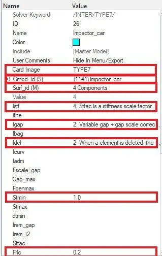
Recommended parameters
- Remove all intersections to get physical results and to avoid solver error.
- Igap=2 Set the variable gap to take into account the true distance between parts
- Gapmin = 0.5 Minimum thickness of the model to avoid errors.
- Inacti=6 Remove initial penetrations wherever possible, elsewhere, reduce to less than 30% of the defined gap value.
- Istiff= 4 Stiffness of interface based on the surface of master & slave.
- Stmin=1 Specify a minimum stiffness in the contact to avoid too soft contact.
- Idel=2 Remove slave nodes from contact because of element deletion.
- Iform=2 Sliding forces are computed using stiffness parameters of the interface.
4. Boundary condition
keep the suspension shock tower nodes locked in Z.
Since We don't want the model to fly around and making it more practical We constrain in Z translation and leave others free as to absorb shock and calculate strain and stress on the BIW.
5. Impactor Boundary Conditions
• The impactor assembly contains a spring attached for stability. Create a BCS
collector to fix the free end of the spring.
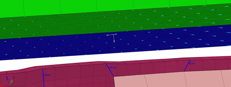
• Create a moving SKEW to define the direction normal to the impactor’s
face.
• Create a BCS collector to guide the master node of the impactor rigid body
so that it is free to translate normal to the face of the impactor, but is fixed
in all other DOFs.
6. Imposed Displacement
• Impose the velocity of the impactor starting from 0 mm/s at t = 0. The
displacement of the impactor should be 200 mm @ 200 ms.
To avoid abrupt changes in the acceleration of the impactor. we give a linear speed -time curve.
In modle tab right-click and select CREATE>CURVE
in x give value 0 and in Y give 0
other point give 200 in X and give 200 in Y.
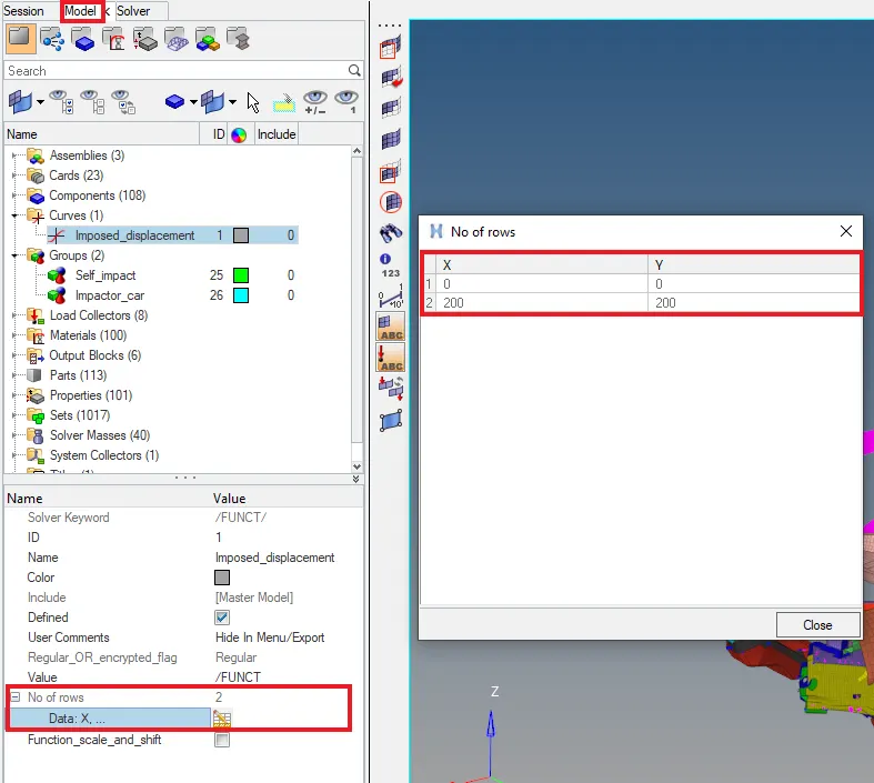
- Create Local skew. keeping Z as perpendicular to bottom of impactor.
- Then, in solver Tab Create IMPDISP imposed displacement.
IN grnd_ID select master node since all other nodes of impactor node will follow the master.
In fct_ID select the curve it has to follow for linear speed.
Select skew_ID and select the local skew we created.
Select Dir as Z direction as the direction of travel.
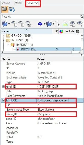
7. Control Cards
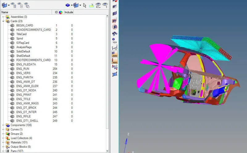
From Analysis select control cards and add these cards
• /ANALY card :Defines the type of analysis and sets analysis flags.
• /DEF_SHELL card: Sets default values for certain parameters in shell property (/PROP/SHELL).
• /DEF_SOLID card : Sets default values for certain parameters in solid property (/PROP/TYPE14 (SOLID) and /PROP/TYPE20 (TSHELL)).
• /IOFLAG card : Describes the input-output flags.
• /SPMD card : Sets SPMD parameters for Hybrid Massively Parallel Program (HMPP) computation.
• /TITLE card : Input a title.
8. Engine File
- Use a constant nodal time step
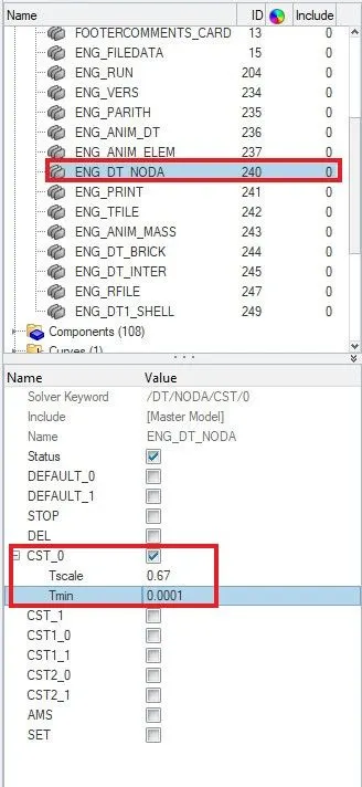
- Print time history every 0.0001 seconds
ENG_TFILE > Time-frequency As 0.1ms
- Solve for 200 ms
ENG_RUN > Tstop : 200
- Create an animation file every 0.005 seconds
ENG_ANIM_DT > Tfreq: 5 ms
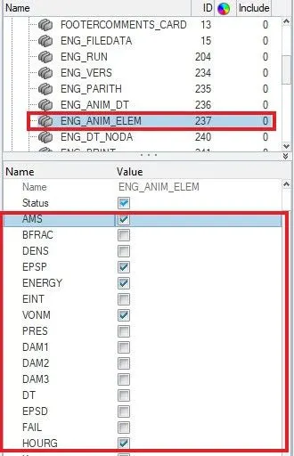
9. Include selected output in animation files:
• Elemental Energy
• Elemental equivalent plastic strain
• Elemental hourglass energy
• Elemental von Mises stress
• Nodal added mass
• Turn on parallel arithmetic
10. Correct rigid bodies if any issues.
Check which parts are not connected to any other part and are simply flying.
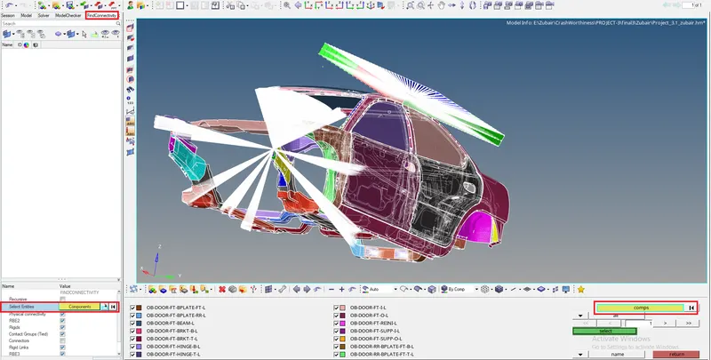
After This do a manual inspection and create connections to make it realistic.
Connections are important in crash as the energy absorption by elements depend on the connection between parts. For instance, if there is no connectivity the force will not get transferred further.
Make connections to parts that are not connected to any other part to check unconnected parts.
Create new components as Rigids and Go to 1D and select rigids make it continuous and multiple node selections. select two-node of the different parts to establish a rigid connection.
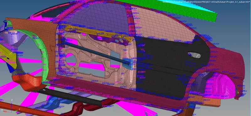
11. Boundary Conditions for Shocktowers:
So the Shock towers are to be constrained in the Z translational axis because if don't the shock absorbers will absorb load and we won't get actual calculations.
During a rollover, we can say that car is upside down and so the load on the roof will be calculated and shock absorbers won't be in action.
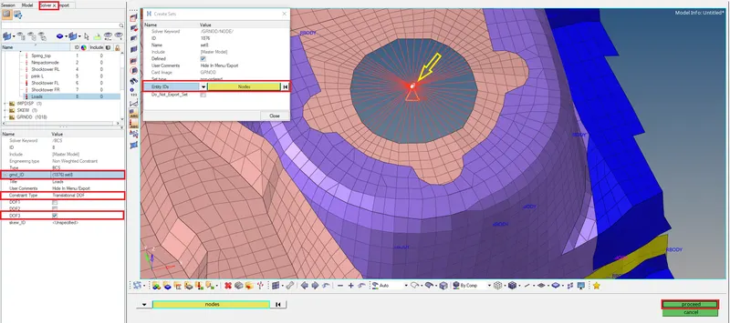
Setting up Boundary conditions.
In solver, right-click and create boundary conditions
From grnd_ID > right click and create edit> select Entity IDs and select center node.
In constraint type, give Translational DOF and select DOF 3 which will constraint in Translational Z-axis. and Proceed.
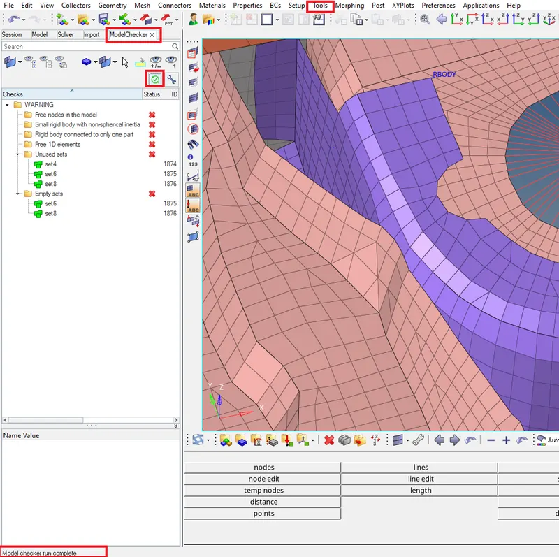
12. Check for any errors :
Go to Tools> Model Checker> Radioss Block> select Run
Here we can Warning, a few of which we can solve and few can be ignored. But there should be no error.
13. Solution and Results Post Processing
• Run the model
• Plot force vs. displacement. Check that the FMVSS 216 target load of
47,000 N (= 3 * GVW) has been met.
• Plot the energy vs. time curves
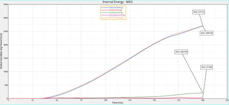
Kinetic Energy: Since this is a Quasi-static loading the energy of the slave node is being calculated here. The slave nodes are in stationary position and do not have kinetic energy but the curve rises slightly as the impactor hit the slave nodes and makes them move. Kinetic energy at the end of the simulation is 21.028
Internal Energy: It is also known as strain energy. the energy absorbed by elements to deform. Internal energy at the end of simulation is 2692.38
Contact Energy: It is the energy used by the Master node of Rigidwall to resist slave nodes to penetrate through it.
Total Energy: It is the summation of Internal Energy + Kinetic energy. Total energy at the end of the simulation is 2713.4
Hourglass Energy: It is the force applied to resist the node to enter into hourglass mode. It usually happens in under integrated element formulation. Since we are using QEPH 24 Modified under integrated formulation it uses the Perturbation method based on stiffness. It applies stiffness before even hourglass arises. Hence Zero Hourglass energy.
Cross plotting.
- In the second Window plot a graph of Impactor-car interface resultant force.
- From 1st window animation Select built plot.
From Result type: select Displacement.
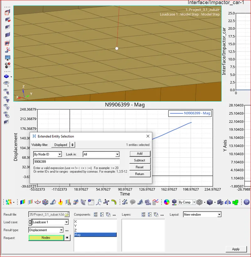
Select Node by id: 9906399 and select Add. We need to calculate displacement based on the impactor.
Select component as Mag and Apply.
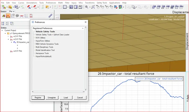
- After plotting the displacement graph. From Files> Load> Preference File> Vehicle Safety Tools and select Load.
- New options will appear in the top tab. Select Math> Two curves> Crossplots And Select already plotted graphs of Impactor resultant force on Y axis and Displacement on X-axis.
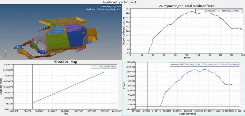
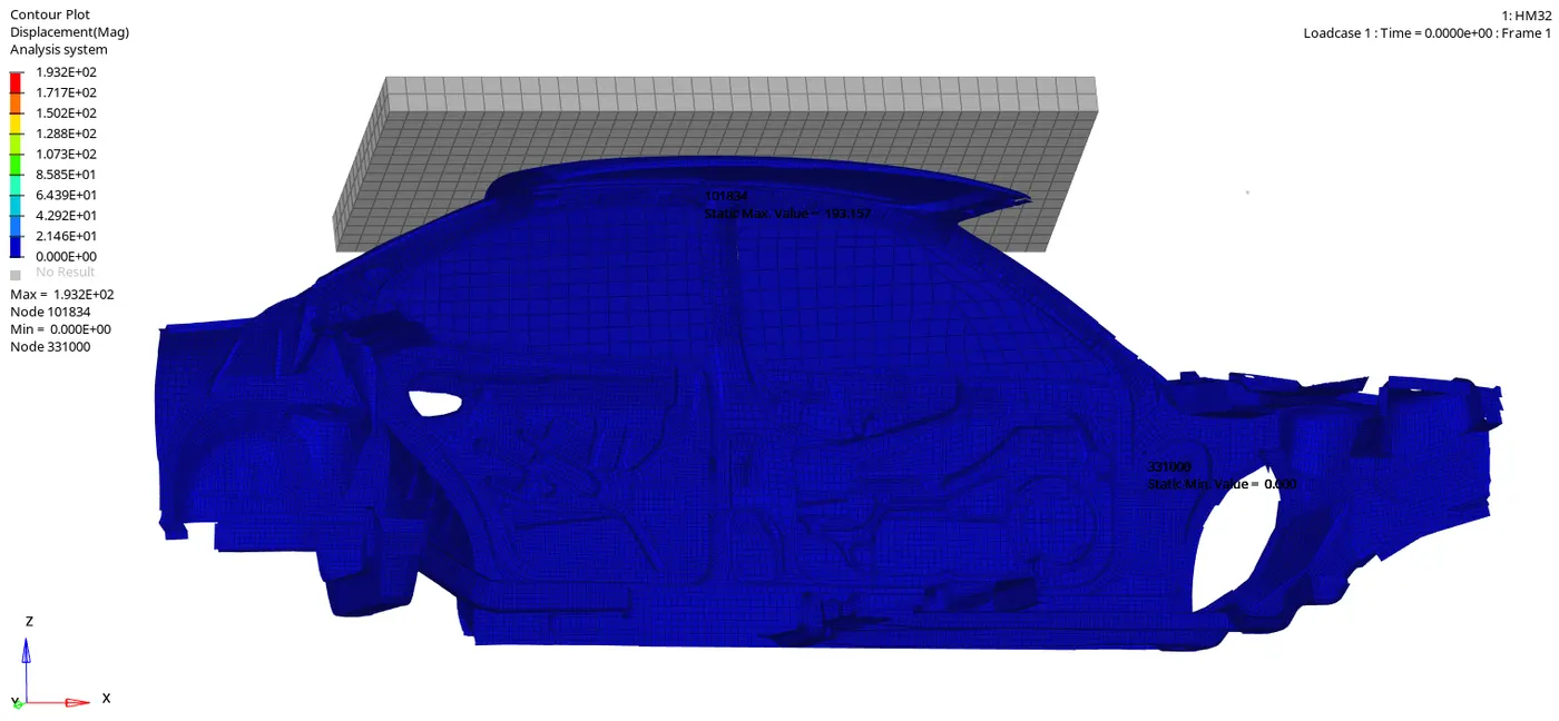
Displacement: Maximum Displacement of a node from was recorded to be 193.15mm.
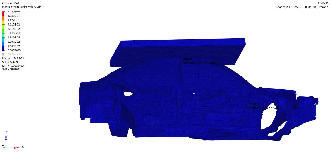
Plastic strain :
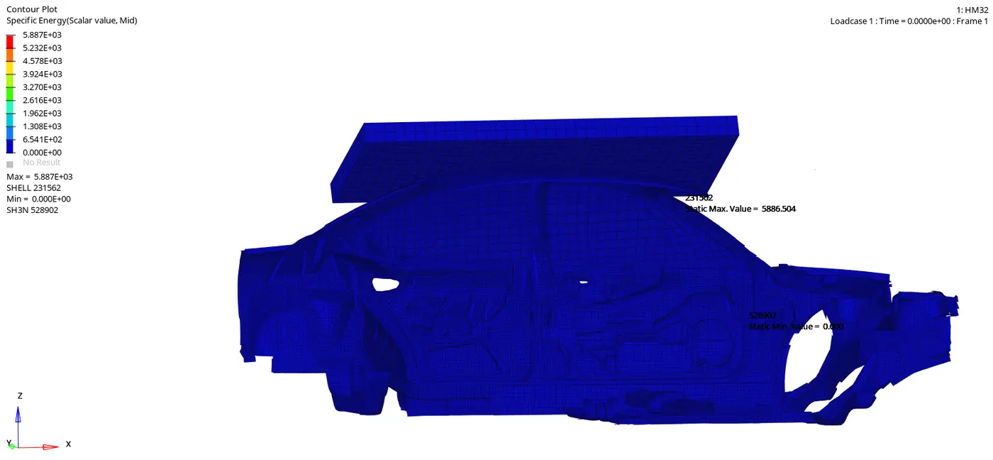
Specific energy:
Specific energy absorption is defined as the energy absorbed per unit mass of material. Here we have maximum specific enegry absorption of 5.86 KJ/Kg by element at roof. Specific energy is an intensive property.
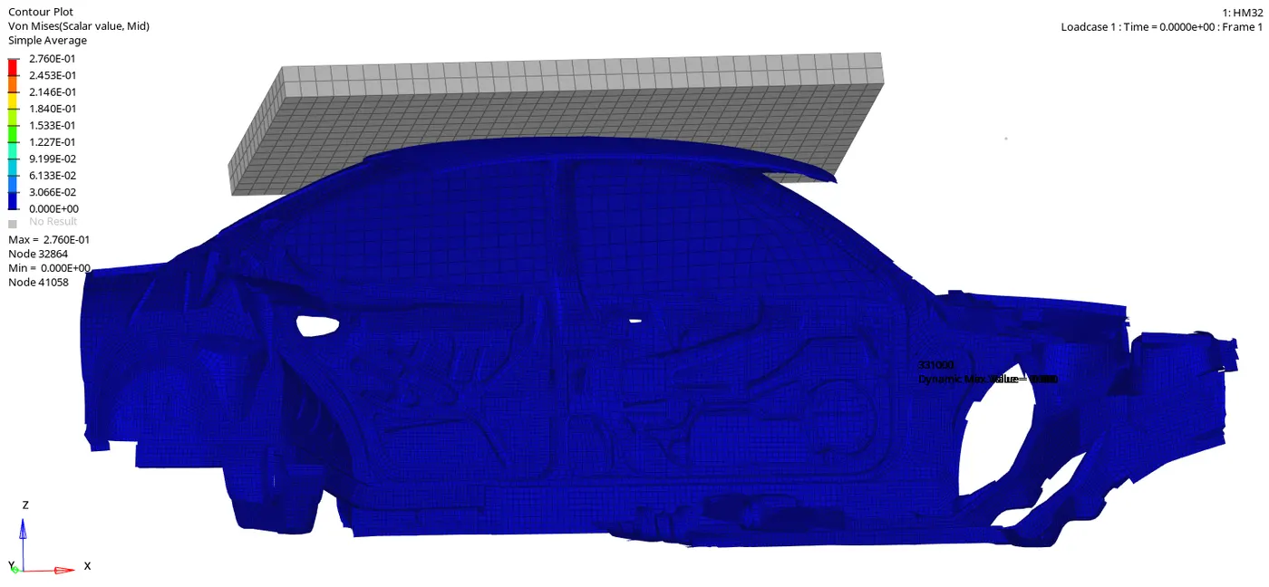
VonMises Stress:
The maximum force required to crush the car is recorded by load cells and then the Strength to weight ratio is calculated
As per FMVSS 216 Government standards :
The minimum resistive force requirement is 1-½ times UVW or 22,240 Newtons (WHICHEVER IS LESS) to be reached at or before 127 millimeters of loading device displacement. But for safety factors, different companies take 3 or 4 times the unloaded vehicle weight.
CONCLUSION
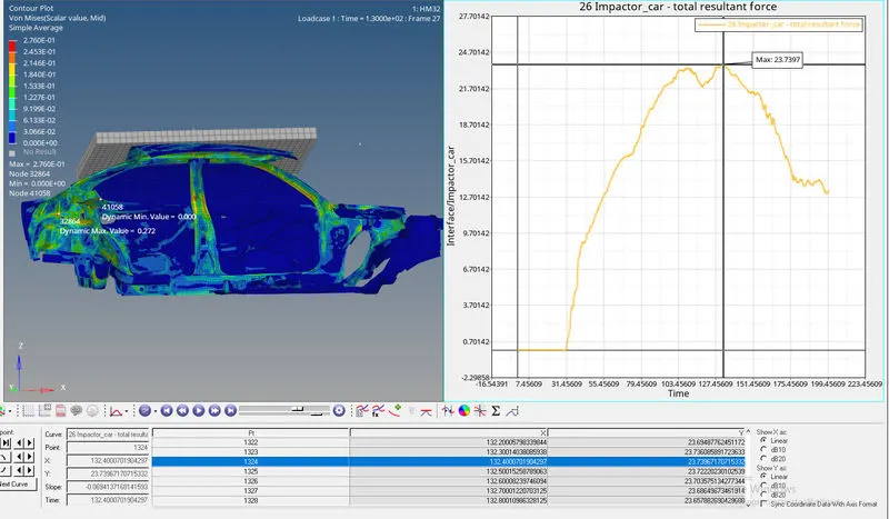
We can see that the maximum Force that we get is 23.7KN at around 132 mm displacement of the master node of the Rigid body of the Impactor in the simulation. Since We have given a curve with a linear relationship between Displacement and time so the Displacement at 132 ms is 132mm.
To check if the FMVSS 216 target load of 47,000 N (= 3 * GVW) has been met, we must know the Gross Vehicle Weight (GVW) of our model. In our case, it is 174.05kg. Since its a student version we'll refer weight of the Whole actual vehicle weight (1600Kg).
To now convert this into weight, we must multiply it by 9.81, then we get 11,934.35N. And, as a Factor of Safety, we multiply this value by 3 and get the Target load as 47,088N.
Since our value 23.7KN is lesser than the specified value of 47,000N, we can conclude that the this condition has been satisfied and met properly.