Calculation of Stiffness in Structural elements
1Q]
AIM: -
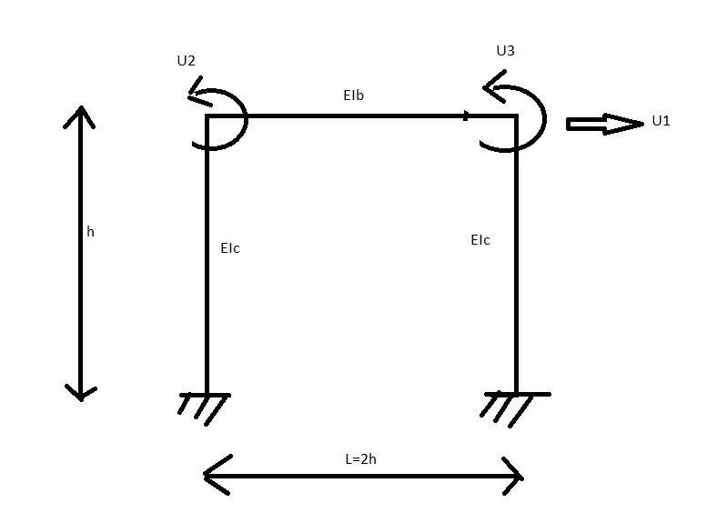
Compute lateral stiffness of the one-storey frame with an intermediate realistic stiffness of the beam.
PROCEDURE: -
We use STIFFNESS co-efficient to analyse the given structure.
Stiffness is defined as force required too produce unit deformation
Stiffness is defined as moment required to produce unit rotation.
K=F/`delta` `delta` = displacement
K=M/`theta` `theta` = slope
Types: -
Axial Stiffness
Transverse Stiffness
Flexural Stiffness
While analysis Axial stiffness, deformation is allowed only in the direction of co-ordinate 1
and all other deformations are restricted.
K11 = Force at 1 to produce unit displacement at 1.
Kij = =Force at i to produce unit displacement at j.
While analysis Transverse stiffness, deformation is allowed only in the direction of co-ordinate 2 and all other deformations are restricted.
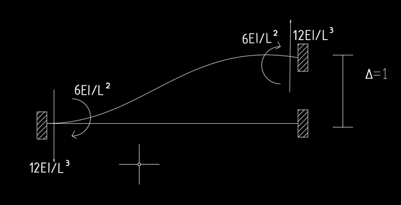
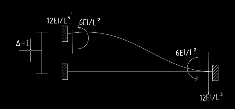
While analysis Flexural stiffness, deformation is allowed only in the direction of co-ordinate 3 and all other deformations are restricted.
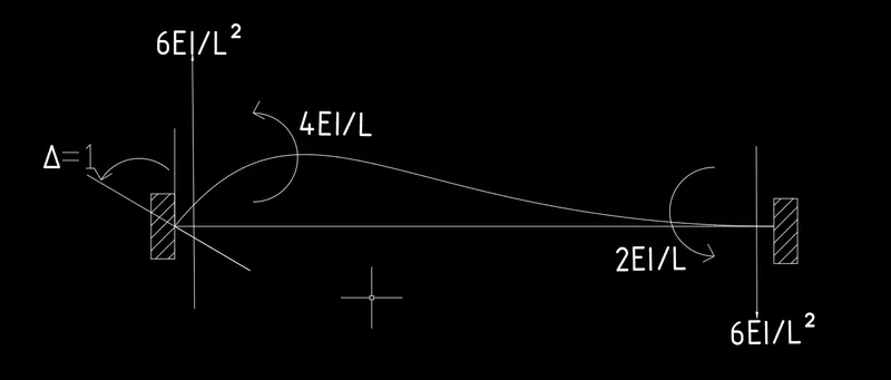
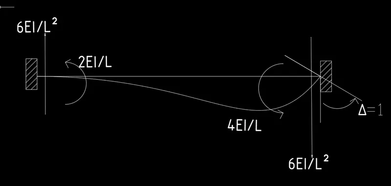
The given structure has 3 Degree of Freedom.
U1 = Transverse displacement
U2= Flexural Stiffness @ joint 1
U3 = Flexural Stiffness @ joint 2
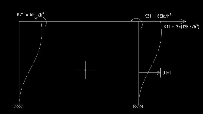
To obtain the first column of the stiffness matrix, we impose unit displacement in DOF u1=1, and all other deformations are restricted i.e. u2 = u3 = 0.
The forces Ki1 required to maintain this deflected shape are shown in Fig.
K11 = 2 * (12EIc/h^3) = 24EIc/h^3
K21 = 6EIc/h^2
K31 = 6EIc/h^2
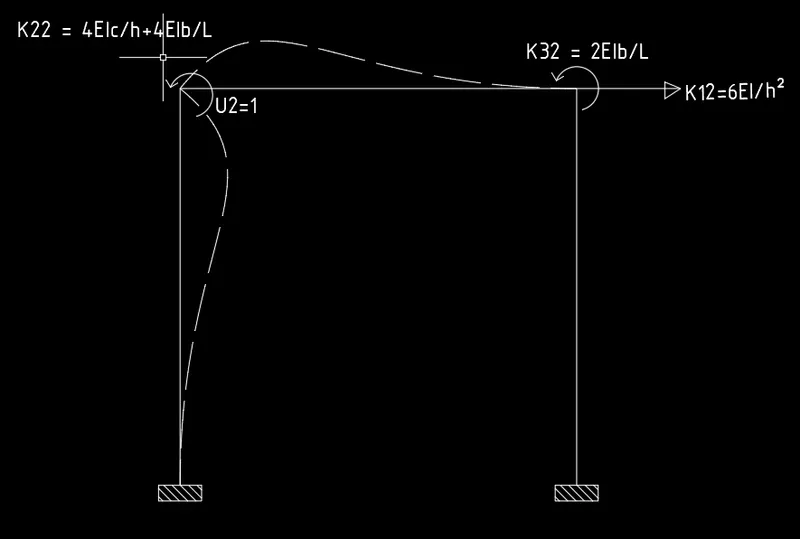
The elements Ki2 in the second column of the stiffness matrix are determined by applying
u2 = 1 and all other deformations are restricted i.e. u1 = u3 = 0.
K12 = 6EIc/h^2
K22 = 4EIc/h + 4EIb/L
K32 = 2EIb/L
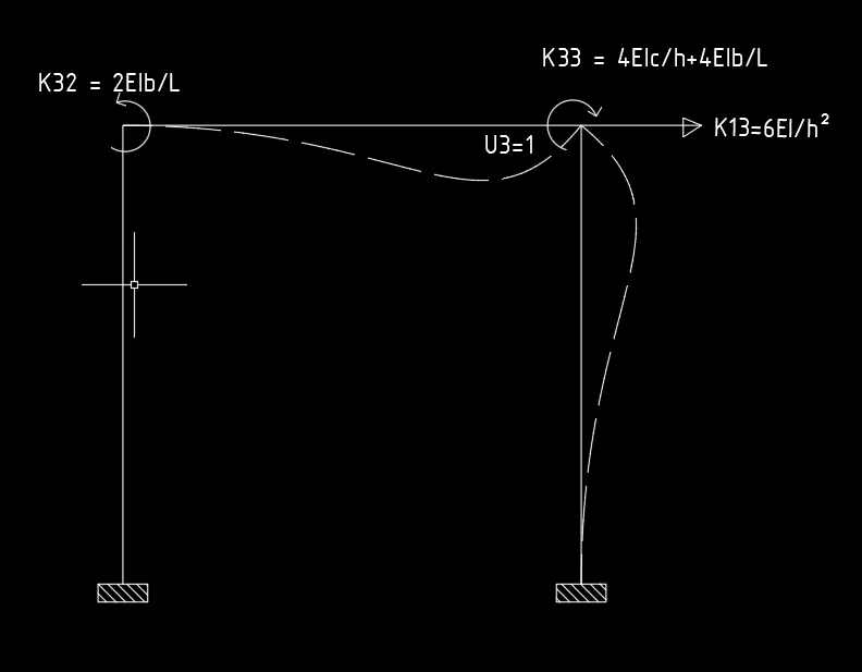
Similarly, the elements ki3 in the third column of the stiffness matrix are determined by applying u3 = 1 and all other deformations are restricted i.e. u1 = u2 = 0
K13 = 6EIc/h^2
K23 = 2EIb/L
K33 = 4EIc/h + 4EIb/L
Given that
L = 2h
Ib = Ic
Putting all the stiffness co-efficient into matrix.
We get
K = `(EIc)/h^3[[24,6h,6h],[6h,6h^2,h^2],[6h,h^2,6h^2]]`
We know that
K*u = F
u = `((u1),(u2),(u3))`
F = `((Fs),(0),(0))`
`(EIc)/h^3[[24,6h,6h],[6h,6h^2,h^2],[6h,h^2,6h^2]]`* `((u1),(u2),(u3))` = `((Fs),(0),(0))`
24*u1 + 6h*u2 + 6h*u3 = Fs eqn..... (1)
6h*u1 + 6`h^2`*u2 + `h^2`*u3 = 0 eqn..... (2)
6h*u1 + `h^2`*u2 + `6h^2`*u3 = 0 eqn..... (3)
Subtract eqn..(2) from eqn..(3)
We get u2 = u3
u3 = -`6/(7h)u1`
u2 = -`6/(7h)u1`
Substitute u2 = u3 and u3 = -`6/(7h)u1` in eqn..(1)
Fs = `96/7*(EIc)/h^3`*u1
By comparing the above equation to the formula
K*U =F
K = `96/7*(EIc)/h^3`
(OR)
We can express joint rotations in terms of lateral displacement using Static Condensation method
STATIC CONDENSATION METHOD is employed to reduce the no of degrees of freedom in an analysis.
It is actually performing part of the solution before assembling the system of equations.
`((u2),(u3))` = `[[6h^2,h^2],[h^2,6h^2]]^-1`* `((6h),(6h))`*u1
By solving the above matrices we express u2 and u3 in terms of u1
= -`6/(7h)``((1),(1))`u1
Substitute these values to calculate Fs
Fs = `((24EIc)/h^3 - (EIc)/h^3 [[6h,6h]] ((1),(1)))*u1`
Fs = `96/7*(EIc)/h^3`*u1
By comparing the above equation to the formula
K*U =F
K = `96/7*(EIc)/h^3`
RESULT: -
We computed Lateral stiffness (K) of the one-storey frame with an intermediate realistic stiffness of the beam.
K = `96/7*(EIc)/h^3`
2Q]
AIM: -
To determine the no of degrees of freedom for Dynamic Analysis.
To establish the Equation of Motion.
To calculate their Natural Frequencies.
a)
PROCEDURE: -
DYNAMIC DEGREES OF FREEDOM
The no of independent displacement (deformation) components that must be considered to represent the effects of all significant inertia forces of a structure.
Based on the co-ordinates to describe the motion:
- Single Degree of Freedom
Ex: - One Storey building
- Multiple Degree of Freedom
Ex: - Multi-storey Building
- Continuous System
Ex: - Chimney
Single Degree of Freedom (SDoF)
A single co-ordinate is sufficient to define the position or geometry of the mass of the system at any instant of time is called SINGLE DEGREE OF FREEDOM.
Co-ordinate is direction and location in which displacement is considered.
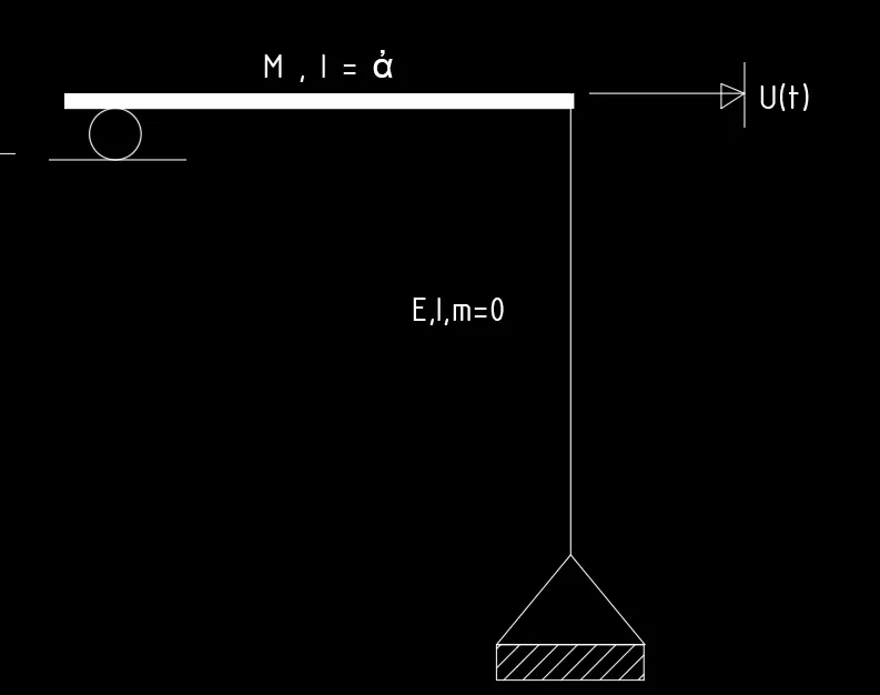
In the given figure it is the one-storey frame, constrained to move only in the direction of the excitation.
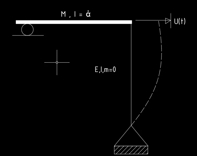
As per Dynamic Analysis, the frame has only one DOF—lateral displacement.
The system has SINGLE DEGREE OF FREEDOM.
In the given figure, the column is pinned/hinge at bottom
From the Slope deflection equations, the stiffness co-efficient for the frame element.
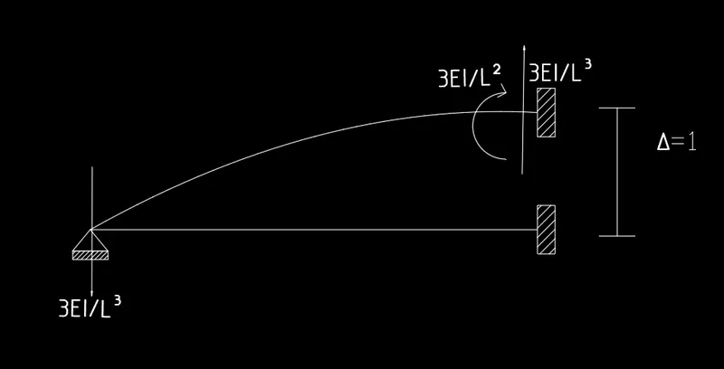
Stiffness K = `(3EI)/h^3`
EQUATION OF MOTION
Differential equation describing the motion of the structure is known as Equation of Motion.
`mddot x + c dotx + kx = F(t)`
`ddotx` = Acceleration of the mass
`dotx` = Velocity of the mass
x = Lateral displacement
K = tiffness co-efficient
C = Damping co-efficient
m = mass of the system
F(t) = Applied force varying with Time
In the given figure, no external force is applied.
So, F(t) = 0
In the given figure, no Damping is provided
so, C = 0
This is the Undamped Free Vibration- SDoF
Equation of motion becomes
`mddot x + kx = 0`
NATURAL FREQUENCY `(omega_n)`
The no of cycles of free vibration in one second for the undamped system is called Natural frequency.
It is the natural property of the system when allowed to vibrate freely without any external excitation.
These vibration properties are independent of the initial displacement and velocity.
`omega_n=sqrt(K/m)`
K = `(3EI)/h^3`
`omega_n=sqrt((3EI)/(Mh^3))`
b)

PROCEDURE: -
DYNAMIC DEGREES OF FREEDOM
The no of independent displacement (deformation) components that must be considered to represent the effects of all significant inertia forces of a structure.
In the given figure it is the one-storey frame, constrained to move only in the direction of the excitation.
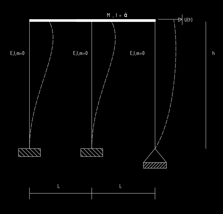
As per Dynamic Analysis, the frame has only one DOF—lateral displacement.
If a single co-ordinate is sufficient to define the position or geometry of the mass of the system at any instant of time is called SINGLE DEGREE OF FREEDOM.
Co-ordinate is direction and location in which displacement is considered.
The system has SINGLE DEGREE OF FREEDOM.
In the given figure, one column is pinned/hinge support and 2 columns are fixed end support at bottom.
From the Slope deflection equations, the stiffness co-efficient for the frame element.
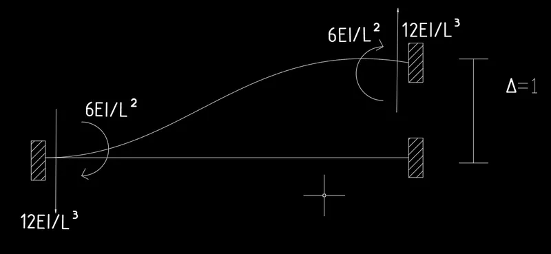
Stiffness co-efficient at fixed End K1 and K2 = `(12EIc)/h^3`
Stiffness co-efficient at Hinge support K3 = `(3EI)/h^3`
If two springs are connected such that under action of force their displacements are same and their forces are different then the springs are in parallel.
In the given structure, displacements of all the 3 columns will be same under action of force.
All the stiffness of the columns will act simultaneously, therefore columns are in parallel.
When the columns are in parallel, displacement is same and forces are different.
F= f1+f2+f3
`K_e`= k1 + k2 + k3
K = `(12EIc)/h^3`+ `(12EIc)/h^3`+ `(3EI)/h^3`
K = `(27EI)/h^3`
EQUATION OF MOTION
Differential equation describing the motion of the structure is known as Equation of Motion.
`mddot x + c dotx + kx = F(t)`
In the given figure, no external force is applied.
So, F(t) = 0
In the given figure, no Damping is provided
so, C = 0
This is the Undamped Free Vibration- SDoF
Equation of motion becomes
`mddot x + kx = 0`
NATURAL FREQUENCY `(omega_n)`
`omega_n=sqrt(K/m)`
K = `(27EI)/h^3`
`omega_n=sqrt((27EI)/(Mh^3))`
RESULT: -
a)
We determined the no of degrees of freedom for Dynamic Analysis.---- SDoF
Established the Equation of Motion. `mddot x + kx = 0`
Calculated their Natural Frequencies. `omega_n=sqrt((3EI)/(Mh^3))`
b)
We determined the no of degrees of freedom for Dynamic Analysis.---- SDoF
Established the Equation of Motion. `mddot x + kx = 0`
Calculated their Natural Frequencies. `omega_n=sqrt((27EI)/(Mh^3))`
3Q]
AIM: -
Determine the Natural Time period of the given system.
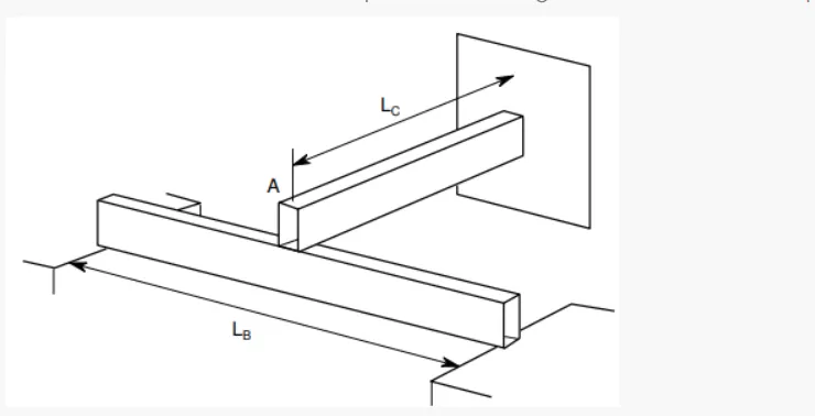
PROCEDURE: -
The time required for the undamped system to complete one cycle of free vibration
is called Natural Time Period.
It is denoted as Tn and its units are seconds.
It is related to the natural circular frequency of vibration, ωn, in units of radians per second.
`T_n`= `(2pi)/omega_n`
`omega_n=sqrt(K/m)`
Now, we have to calculate Keff for simply supported beam and cantilever beam.
Simply Supported Beam
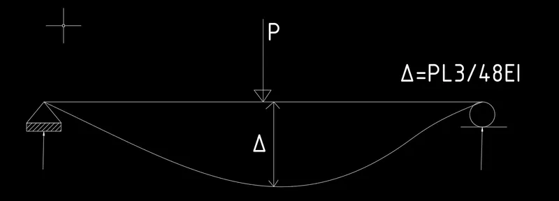
`delta= (PL^3)/(48EI`
`K = P/delta`
`K_b=(48EI)/(l_b^3)`
Cantilever Beam.
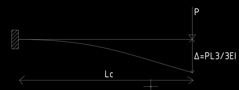
`delta= (PL^3)/(3EI`
`K = P/delta`
`K_c= `(3EI)/(l_c^3)`
If two springs are connected such that under action of force their displacements are same and their forces are different then the springs are in parallel.
In the given structure, displacements of all the 2 beams will be same under action of force.
All the stiffness of the beams will act simultaneously, therefore beams are in parallel.
When the beams are in parallel, displacement is same and forces are different.
F= f1+f2
`K_e`= k1 + k2
`K_e=(3EI)(1/(l_c^3)+16/(l_b^3))`
Natural Frequency: -
`omega_n=sqrt(K/m)`
`omega=sqrt(((3EI)(1/(l_c^3)+16/(l_b^3)))/M)`
Time Period: -
`T=(2pi)/sqrt(((3EI)(1/(l_c^3)+16/(l_b^3)))/M)`
M = mass of the system
K = effective stiffness of the system
T = Time period
RESULT: -
We calculated Ke and natural frequency of the system and then
We determined the Natural Time period of the given system
`T=(2pi)/sqrt(((3EI)(1/(l_c^3)+16/(l_b^3)))/M)`
4Q]
AIM:-
Determine the Effective Stiffness of the given systems.
a)
PROCEDURE: -
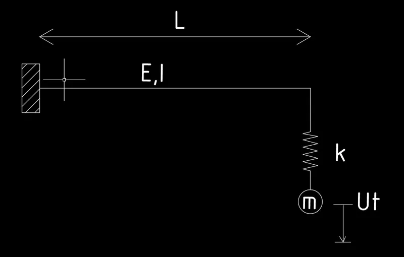
We can see that Mass "m" is attached at bottom of the spring.
Spring is attached to the Cantilever beam.
Draw the Free body diagram of the given system.
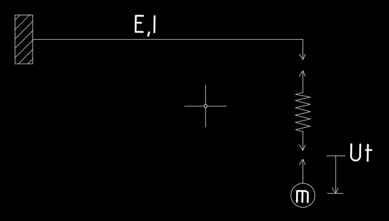
Stiffness of the spring is given as K
Now, we have to calculate the Stiffness of the Cantilever beam.
`delta= (PL^3)/(3EI`
`K = P/delta`
`K_b= (3EI)/(L^3)`
If two springs are connected such that under action of force their displacements are different and their forces are same.
All the stiffness of the beam and spring are not acting simultaneously, acting one after the other
then the beam and spring are in series.
`1/K_e=1/K_b+1/K`
`1/K_e=1/((3EI)/L^3)+1/K`
`1/K_e=L^3/((3EI))+1/K`
`1/K_e=(KL^3+3EI)/(3EIK)`
`K_e=(3EIK)/(KL^3+3EI)`
Ke = Effective Stiffness
K = Stiffness co-eff of spring.
`K_e=(3EIK)/(KL^3+3EI)`
b)
PROCEDURE: -
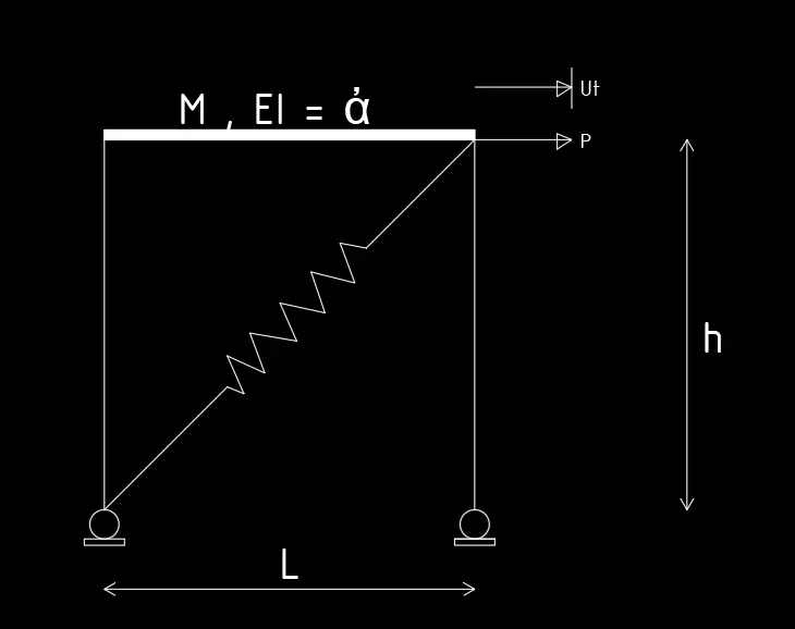
Given that the Stiffness co-eff of spring is K
but the spring is inclined.
The applied and force and discplacement are in horizontal plane.
We have to deduce the inclined Stiffness co-eff in the spring.
lets draw the F.B.D of the system.
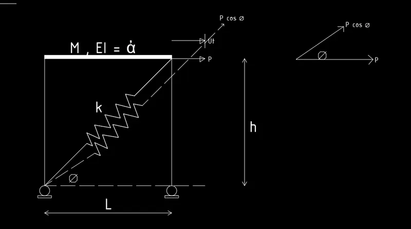
From the Figure we can see that the sprig elongated
So, we have to calculate the inclined components to arrive actual co-eff of the spring.
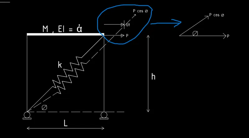
From the figure we can see that
The inclined component of Load P = `p/cos theta`
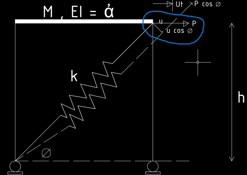
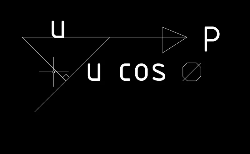
From the figure we can see that
The inclined component of displacement u = `u cos theta`
From the definition of the Stiffness co-eff
K = `P/delta`
P = `p/cos theta`
`delta = u cos theta`
K = `P/cos^2 theta`
`P/u = Kcos^2 theta`
Now, Calculate the value of `cos theta`
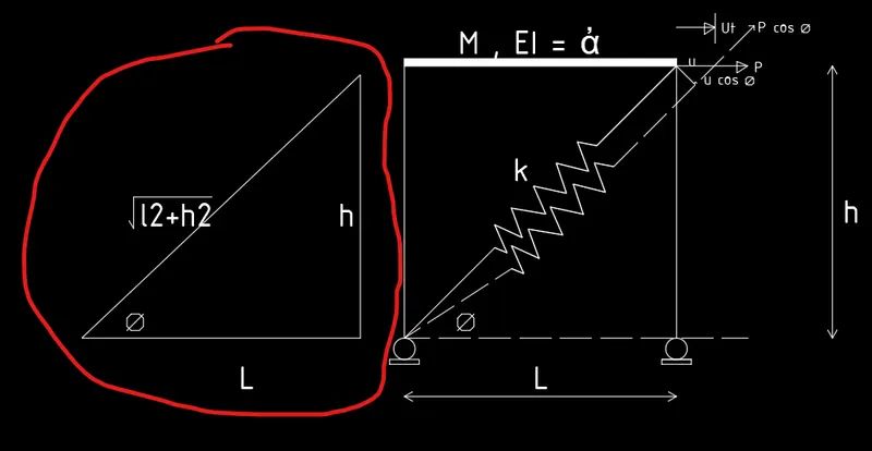
`cos theta = L/(sqrt(L^2+h^2`
`cos^2 theta = L^2/(L^2+h^2)`
`K_2= K*L^2/(L^2+h^2`
Stiffness of Vertical columns: -
`K_1= (3EI)/(h^3)`
2 columns are present
`K_1= (3EI)/(h^3) + (3EI)/(h^3) = (6EI)/h^3`
All the stiffness of the beams will act simultaneously, therefore beams are in parallel.
When the beams are in parallel, displacement is same and forces are different.
F= f1+f2
`K_e`= k1 + k2
`K_e= (6EI)/h^3 + (KL^2)/(L^2+h^2`
C]
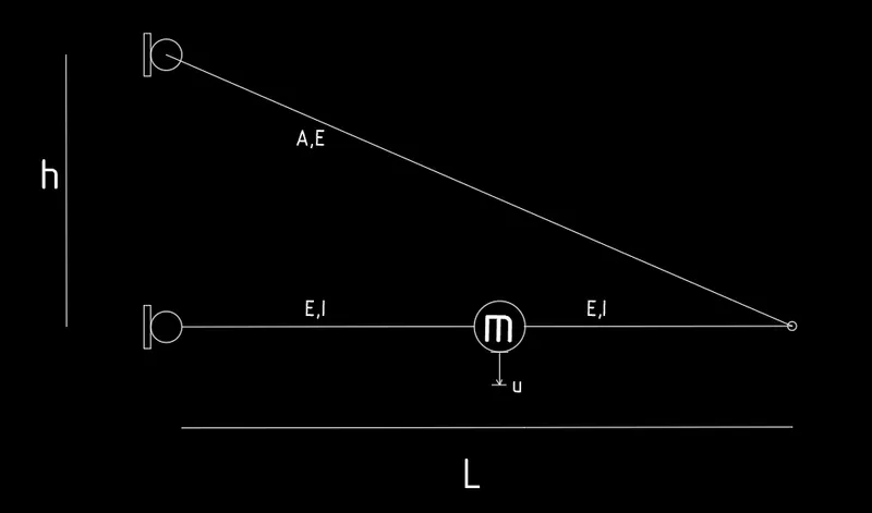
PROCEDURE: -
For the given figure,
Lets assume the inclined struct as vertical strut.
Now the structure looks as
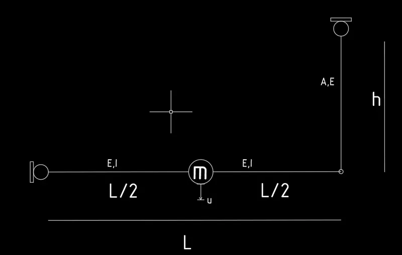
Lets draw the F.B.D for the above system
Lets divide the system into Horizontal strut and vertical strut
Reactions on horizontal strut because of the mass "m" is
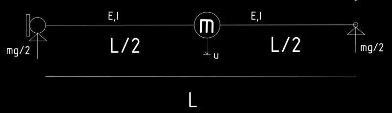
To keep the system in equilibrium the force in the vertical strut would be
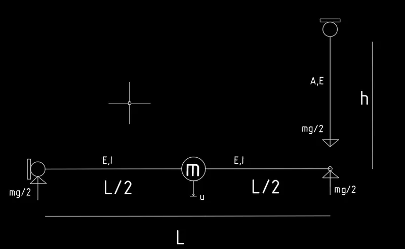
The stiffness co-eff of horizontal strut beacause of mass "m"
P = mg
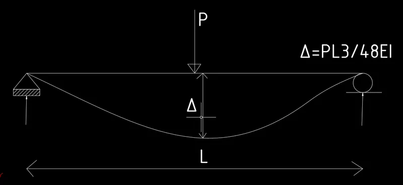
The stiffness co-eff of pinned-pinned beam is
`K_1= (48EI)/(L^3)`
To get the Effective stiffness we have to add the axial stiffness provided by the inclined strut.
Lets calculate the deformation caused by inclined strut at mass "m"
Reaction at Right node is mg/2 beacause of mss "m".
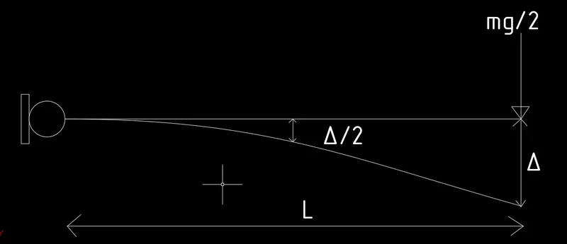
`Delta_(ea,vert) = 2*Delta`
F = `K_(ea,vert)` * `2*Delta`
`F = (mg)/2`
`(mg)/2 = K_(ea,vert)*2Delta`
`(mg)/Delta = 4* K_(ea,vert)`
`K_2 = 4* K_(ea,vert)`
Now, we have to calculate inclined stiffness
For this, we have to convert vertical axial stiffness to inclined axial stiffness.
The inclined component of Load P = `p/cos theta`
The inclined component of displacement u = `u cos theta`
`K_(ea)= p/u`
`K_(ea)= p/(ucos^2theta)`
`p/u= K_(ea)cos^2theta`
but `p/u = K_(ea,vert)`
Replace p/u with `K_(ea,vert)`
`K_(ea,vert) = K_(ea)cos^2theta`
we know that
`cos^2 theta = h^2/(L^2+h^2)`
`K_2 = 4*K_(ea,vert)`
`K_2= (4K_(ea)*h^2)/(L^2+h^2`
If two springs are connected such that under action of force their displacements are different and their forces are same,then springs are in series.
All the stiffness of the beams are not acting simultaneously, acting one after the other
then the beams are in series.
`1/K_e=1/K_1+1/K_2`
`K_1= (48EI)/(L^3)`
`K_2= (4K_(ea)*h^2)/(L^2+h^2`
`1/K_e=1/((48EI)/l^3)+1/((4k_(ea)h^2)/(l^2+h^2)`
`1/K_e=1/((48EI)/l^3)+1/((4EAh^2)/(l^2+h^2)^(3/2)`
`1/K_e=((4EAh^2)/(l^2+h^2)^(3/2)+(48EI)/l^3)/(((48EI)/l^3)*((4EAh^2)/(l^2+h^2)^(3/2))`
`K_e=((48EI)/l^3*(4EAh^2)/(l^2+h^2)^(3/2))/((4EAh^2)/(l^2+h^2)^(3/2)+(48EI)/l^3`
RESULT: -
We determined the Effective Stiffness of the given systems.
a)
Effective stiffness =
`K_e=(3EIK)/(KL^3+3EI)`
b)
Effective stiffness =
`K_e= (6EI)/h^3 + (KL^2)/(L^2+h^2`
c)
Effective stiffness =
`K_e=((48EI)/l^3*(4EAh^2)/(l^2+h^2)^(3/2))/((4EAh^2)/(l^2+h^2)^(3/2)+(48EI)/l^3`