Calculation of Stiffness in Structural elements
Question 1:
Compute lateral stiffness of the one-story frame with an intermediate realistic stiffness of the beam. The system has 3 DOFs as shown. Assume L = 2h and Elb = Elc
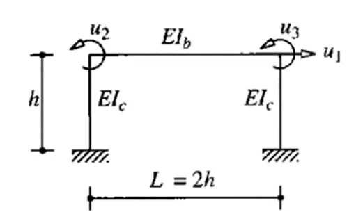
AIM
To compute lateral stiffness of one storey building with the given parameters.
PROCEDURE
The stiffness matrix of the above problem can be written as
`[[k_11, k_12, k_13], [k_21, k_22, k_23], [ k_31, k_32, k_33]] * [ [u_1] , [u_2], [u_3]] = F_s`
To obtain the stiffness matrix,
Consider unit force at u1 = 1 and u2=u3=0, we get;
`k_11 = frac{2(12EI_c)}{h^3} , k_21= k_31 = frac {6EI_c}{h^2}`
Similarly, considering u2=1 and u1=u3=0, we get;
`k_12 = frac{6EI_c}{h^2} , k_22 = frac {4EI_c}{h} + frac {4EI_b}{L}, k_32 = frac {2EI_b}{L}`
Similarly, considering u3 = 1 and u1=u2=0, we get;
`k_13 = frac{6EI_c}{h^2} , k_23 = frac {EI_c}{h} , k_33 = frac {2EI_c}{L}`
Since we know, Ic= Ib and L=2h, we can write the stiffness matrix as follows:
`frac {EI_c}{h^3} [[24,6h,6h],[6h,6h^2,h^2],[6h,h^2,6h^2]] * [[u_1],[u_2],[u_3]] = [[f_s],[0],[0]]`
From the second and third equations, using static condensation method the joint rotations can be expressed in terms of lateral displacement as follows:
`[[u_2],[u_3]] = -[[6h^2, h^2],[h^2,6h^2]]^-1 [[6h],[6h]] * u_1 = -frac {6}{7h} * [[1],[1]] * u_1`
Substituting this in the above equation and solving, we get;
`k=frac{96EI_c}{7h^3}`
Question 2:
For the following structures:
- Determine the number of degrees of freedom for dynamic analysis
- Establish the equation of motion
- Calculate their natural frequencies
(a)
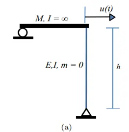
AIM
To find the number of degrees of freedom, establish the equation of motion and calculate the natural frequency for the given system.
PROCEDURE
DOF = 1
Equation of motion is obtained as
`m ddot u + ku = 0`
Stiffness of the given frame is
`k = sqrt frac {3EI} {h^3}`
we know that
`omega_n = sqrt frac {k}{m}`
Now, substituting the value of k, in the above equation, we get
`omega_n = sqrt frac {3EI}{mh^3}`
(b)
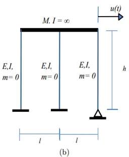
AIM
To find the number of degrees of freedom, establish the equation of motion and calculate the natural frequency for the given system.
PROCEDURE
DOF = 1
Equation of motion is obtained as
`m ddot u + ku = 0`
Stiffness of the given frame is
`k = frac{2(12)EI} {h^3} + frac {3EI} {h^3}`
`k = frac{27EI} {h^3}`
we know that
`omega_n = sqrt frac {k}{m}`
Now, substituting the value of k, in the above equation, we get
`omega_n = sqrt frac {27EI}{mh^3}`
Question 3:
Consider the propped cantilever shown in the figure below. The beams are made from the same steel section and have lengths as shown on the diagram. Determine the natural period of this system if a large mass, M, is placed at the intersection of the beams at point A. The weight of the beams in comparison with the mass M is very small.
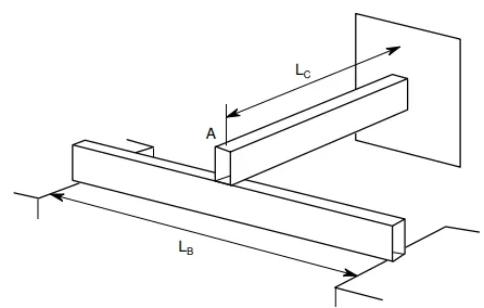
AIM
To calculate the natural period of the given system.
PROCEDURE
In the above diagram, there are two beams connected to each other: a cantilever beam and a simply supported beam
For cantilever beam, stiffness value is
`k= frac {3EI} {L_c ^3 }`
For simply supported beam, stiffness value is
`k= frac {48EI} {L _b^3 }`
Thus, Ke = k1+k2 =
`k= 3EI [frac {16} {L_b ^3 } +frac{1}{L_c^3}]`
we know that
`omega_n = sqrt frac {k}{m}`
Thus,
`omega_n = sqrt {frac {3EI}{m}[frac {16} {L_b ^3 } +frac{1}{L_c^3}]}`
Time period is given as
`T _n= frac {2pi}{omega_n}`
Question 4
Determine an expression for the effective stiffness of the following systems:
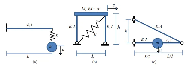
(a)
There are 2 stiffness components connected to the mass. One is a fixed cantilever beam, another is a spring. Both are connected in series with the mass.
So the effective stiffness of the system with components in series.
`frac {1}{k_e} = frac {1} {k_1} + frac{1}{k_2}`
k1 stiffnes of beam
k2 stiffness of spring (k)
`k_1 = frac {3EI} {L ^3 }`
`frac {1}{k_e} = frac {L^3} {3EI} + frac{1}{k}`
`frac {1}{k_e} = frac {kL^3 + 3EI} {3EIk}`
`k_e = frac {3EIk} {kL^3 + 3EI}`
(b)
There are 3 stiffness components connected to the mass. Two of them are fixed-end columns and the third is a spring. All are connected in series to the mass. But the spring is connected inclined to the system, hence its actual stiffness would be different
`k_e = k_1 + k_2+ k_3`
k1 = stiffness of column-1
k2= stiffness of column-2
k3= stiffness of spring K
Stiffness of both the column = `frac {3EI}{h^3}`
To determine the stiffness of spring in the system we have to resolve the deformation(u) and the horizontal force (say F) into perpendicular components
Therefore, Inclined component of force = `F/ cos theta`
inclined component of deformation = `u cos theta`
Force on spring, Force = stiffness(k) x deformation
`F/cos theta = k * u cos theta`
`k= F/(u cos^2 theta) = K/ (cos^2 theta)`
Here, `cos theta = frac {L}{sqrt(L^2 + h^2)}`
therefore,actual stiffness of spring `k= (KL^2)/(L^2+h^2)`
Hence effective stiffness = `(3EI)/h^3 + (3EI)/h^3 + (KL^2)/(L^2+h^2)`
`= (6EI)/h^3 +(KL^2)/(L^2+h^2)`
(c)
There are 2 stiffness components connected to the mass. One is a fixed beam with bending stiffness and another inclined fixed beam with axial stiffness.
k1 = bending stiffness of beam
k2 = axial stiffness of inclined beam
The stiffness of the centrally loaded beam is `frac {48EI}{L^3}`
Determination of stiffness of inclined strut
Assume the strut as vert ical having stiffness kv
Load acting on the strut = mg/2
If the beam gets deflected under load at right end is mg/2 is delta, then by geometry the strut would get deflected by twice of that
therefore `(mg)/2 = k_v * 2 Delta`
`(mg)/Delta =4k_v`
`k_2= 4k_v`
Now resolving the vertical component to get actual stiffness
`k_2= (4k_vh^2)/(L^2+h^2)`
As the two members have their indivdual deflections this implies that the two members are in series
Hence, `1/(k_(eq)) = 1/k_1 + 1/ k_2`
`1/(k(eq))= frac {L^3}{48EI} + frac{L^2+h^2}{4k_vh^2}`
the axial stiffness = `(EA)/(L)`
here the length of iinclined member is = `sqrt(L^2+h^2)`
substituting the value in final equation
`1/(k(eq))= frac {L^3}{48EI} + frac{(L^2+h^2)sqrt(L^2+h^2)}{4EAh^2}`