Calculation of Stiffness in Structural elements
Question 1:
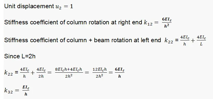
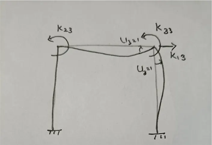
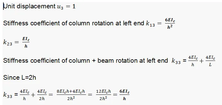
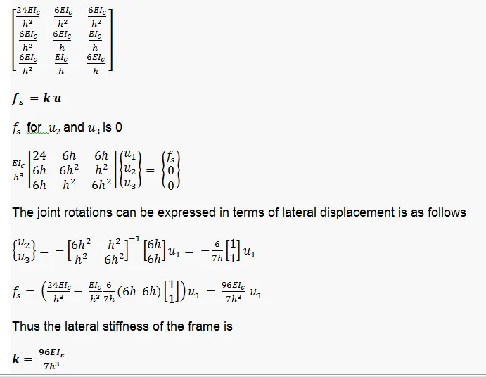
Compute lateral stiffness of the one story frame with an intermediate realistic stiffness of the beam. The system has 3 DOFs as shown. Assume L = 2h and Elb = Elc
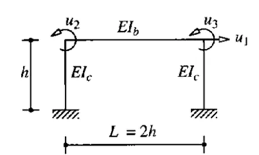
ANS :
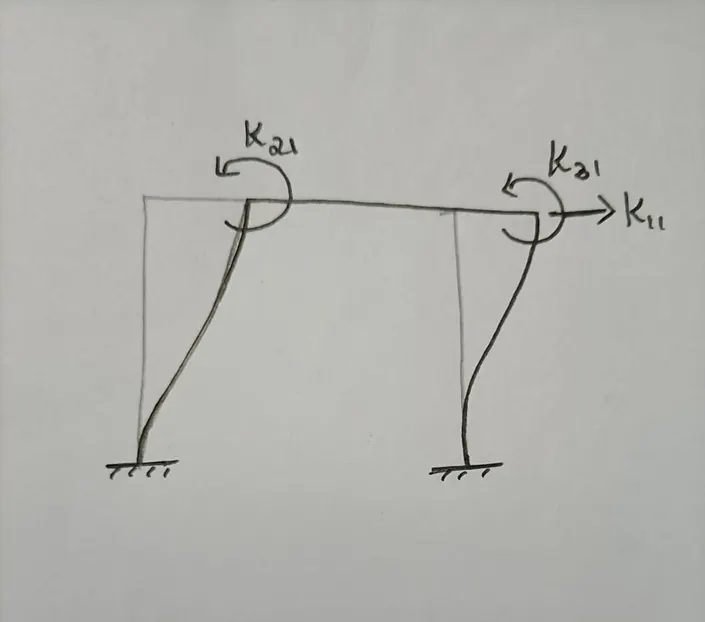
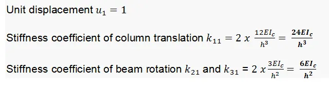
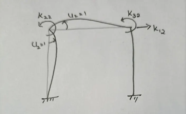
Question 2:
For the following structures:
- Determine the number of degrees-of-freedom for dynamic analysis
- Establish the equation of motion
- Calculate their natural frequencies
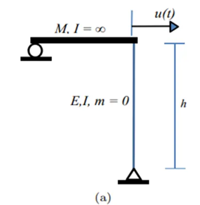
ANS :
Position of the element can be described by coordinate u(t) as shown in figure
The system has single degree of freedom
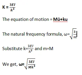
Since the column has fixed end at the bottom, the stiffness coefficient will be as follows
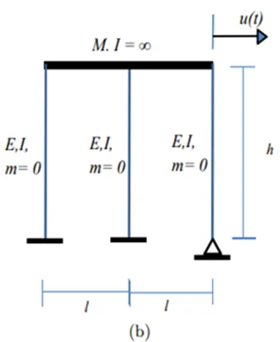
ANS :
Position of the element can be described by coordinate u(t) as shown in figure, because the beam with infinite stiffness will include uniform translation in all columns
The system has single degree of freedom
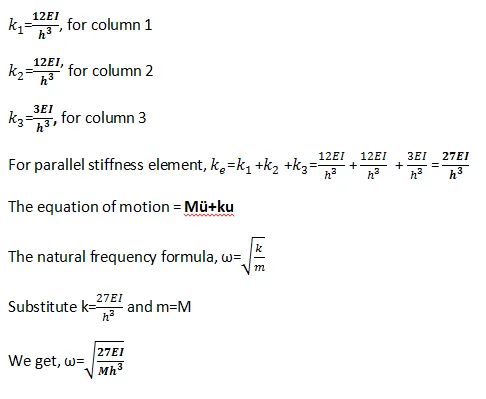
As per the given figure there are two columns with both the ends fixed and one column has pinned fixed end, so the stiffness coefficient will be as follows
Question 3:
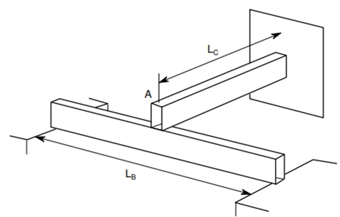
Consider the propped cantilever shown in the figure below. The beams are made from the same steel section and have lengths as shown on the diagram. Determine the natural period of this system if a large mass, M, is placed at the intersection of the beams at point A. The weight of the beams in comparison with the mass M is very small.
ANS:
As per the given question both the elements are made of same material and section. It means they have same modulus of elasticity and second moment of inertia, but the lengths are different.
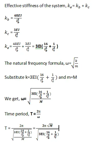
When a mass M is applied at the intersection point A, both the elements will respond simultaneously. This means they are connected in parallel.
Question 4
Determine an expression for the effective stiffness of the following systems:
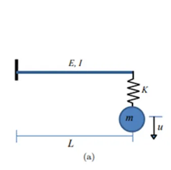
ANS :
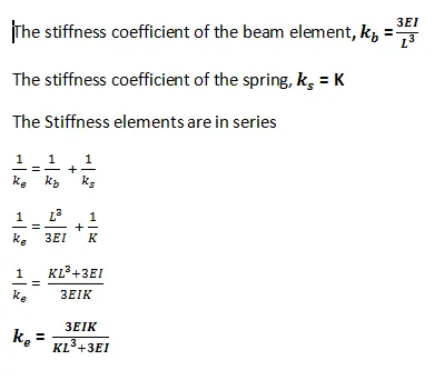
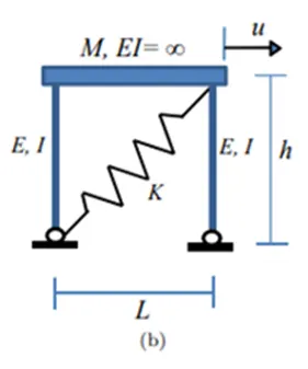
ANS :
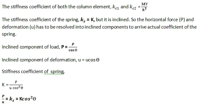
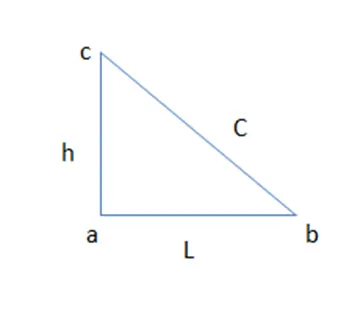
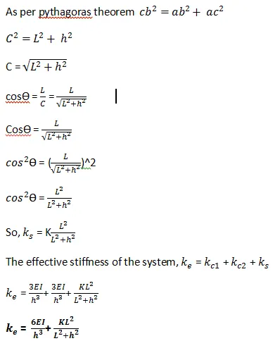
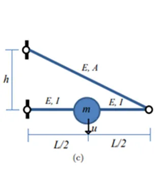
ANS :
The stiffness coefficient of the pinned pinned beam is,

The effective stiffness coefficient for the system has to be formed by adding the relative axial stiffness provided by the inclined strut connected at the right end. The force acting on the right end is mg/2 and the deformation caused by the strut at the point of m is half of its right end nodal deformation.
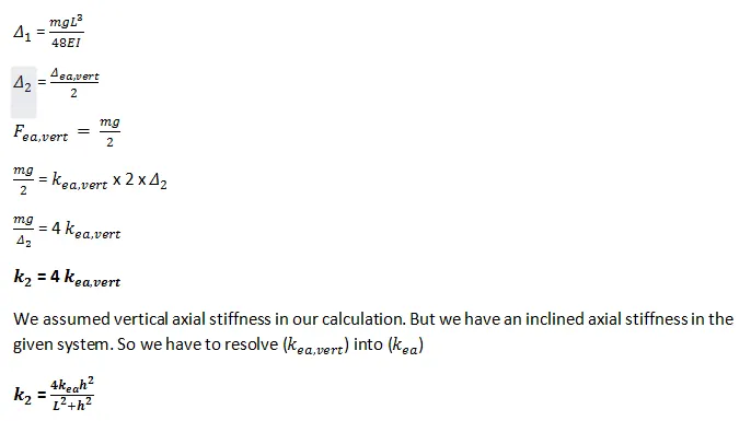
The effective stiffness shall be arrived as
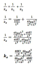
Note : Equations were not coping properly from word file so i have taken screen shots and pasted it and also word file is attached