Calculation of Stiffness in Structural elements
Question 1:
Compute lateral stiffness of the one-story frame with an intermediate realistic stiffness of the beam. The system has 3 DOFs as shown. Assume L = 2h and Elb = Elc
Answer:
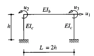
- In the above-given diagram, three different deflections can be seen on the 2D frame.
- U1 is a horizontal deflection whereas U2 and U3 are rotational deflections on the left and right end respectively.
- It is given that the length of the beam is twice the height of the column and the elasticity of the columns and the beam are equal.
- The system has 3 degrees of freedom.
- We need to calculate the stiffness coefficient for each.
- The calculation can be given as follows:
- For U1:
- Let's suppose unit displacement, U1 = 1.
- The stiffness coefficient of both the columns can be given as = 2 * 12EI/h³ = 24EI/h³
- The stiffness coefficient for the beam can be given as= EI/h²
- For U2:
- Let's suppose unit displacement, U2 = 1.
- Stiffness coefficient at the right end = 6EI/h²
- Stiffness coefficient of the column and the beam experiencing the rotation on the left
= 4EI/h + 4EI/L
= 4EI/h + 4EI/2h
= 6EI/h
- For U3:
- Let's suppose unit displacement, U3 = 1.
- Stiffness coefficient at the left end = 6EI/h²
- Stiffness coefficient of the column and the beam experiencing the rotation on the right
= 4EI/h + 4EI/L
= 4EI/h + 4EI/2h
= 6EI/h
- For U1:
- Now we will create a matrix and finally deduce the equation of " f = ku "
- After solving all the values we finally get the answer as U = 96*EI/7h³
Question 2:
For the following structures:
- Determine the number of degrees of freedom for dynamic analysis
- Establish the equation of motion
- Calculate their natural frequencies
Answer:
a)
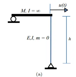
- From the above figure, we can see that only one displacement occurred on the frame. Thus the DOF of the frame is 1
- The equation of the motion for this frame can be given as:
mu" + ku = 0 - Now for natural frequency, we need to find the value of the stiffness coefficient. The stiffness coefficient can be found out as below:
- The column has a fixed end at the bottom, so the stiffness coefficient will be
k1= 3EI/h³ - Now the natural frequency (`omega`)
= `root`(k/m)
= `root`(3EI/mh³)
- The column has a fixed end at the bottom, so the stiffness coefficient will be
b)
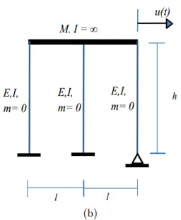
- From the above figure, we can see that only one displacement occurred on the frame. Thus the DOF of the frame is 1
- The equation of the motion for this frame can be given as:
mu" + ku = 0 - Now for natural frequency, we need to find the value of the stiffness coefficient. The stiffness coefficient can be found below:
- The column has a fixed end at the bottom, so the stiffness coefficient will be
k1= 3EI/h³ - The other two columns' stiffness coefficients can be given as:
k2 = k3 = 12EI/h³ - ke = k1 + k2 + k3 = 27EI/h³
- Now the natural frequency (`omega`)
= `root`(k/m)
= `root`(27EI/mh³)
- The column has a fixed end at the bottom, so the stiffness coefficient will be
Question 3:
Consider the propped cantilever shown in the figure below. The beams are made from the same steel section and have lengths as shown on the diagram. Determine the natural period of this system if a large mass, M, is placed at the intersection of the beams at point A. The weight of the beams in comparison with the mass M is very small.
Answer:
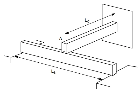
- From the above figure, we can see that two different beams of the same cross-section and material are there.
- The above beam is a prop cantilever type of beam.
- If at point A a load of mass "m" acts in a downward direction then both the beams will show a deflection.
- The below beam will experience deflection at the mid-span, while the cantilever beam will experience deflection at the end, i.e., at point A.
- The stiffness coefficient for the beams can be given as:
kb = 48Ei/Lb³
kc = 3EI/Lc³
ke = kb + kc = 3EI[ (1/Lc³) + (16/Lb³) ] - Now the natural frequency (`omega`)
= `root`k/m
= `root`(ke/m) - Natural period (T)
= 2`pi`/`omega`
= 2`pi`/ `root`(ke/m)
Question 4
Determine an expression for the effective stiffness of the following systems:
Answer:
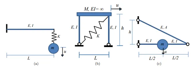
a)
- In the figure (a) we can see there is a cantilever beam which has a supspendend mass "m" at the unsupported end.
- To find the stiffness of the beam:
- Stiffness of the beam; k1 = 3EI/l³
- Stifnedd of spring; k2 = K
- ke = 1/k1 + 1/k2
= 3EIK/( KL³ + 3EI)
b)
- In the figure (b) we can see a frame of two columns and a beam having DOF as 1.
- A spring is attached diagonally.
- For effective stiffness of the whole frame:
- Stiffness for both columns; k1 = 6EI/h³
- As mentioned the stifness of the spring is K but we need to find the inclined stiffness.
- K = P/U
- P = p/cos`theta`
- U = ucos`theta`
- `therefore`K= kcos²`theta`
- Now cos`theta` = h/ `root`( l² + h² )
- `therefore` K = k*h²/( l² + h² )
- ke = k1 + K = 6EI/h³ + k*h²/( l² + h² )
c)
- In the figure (c) we can see that there is a series connection of two beams, of which one is inclined.
- Stiffness of the horizontal beam; k1 = 48EI/L³
- Now for the inclined component;
- There will be two components of that, one is vertical and the other one will be horizontal.
- Calculating the value of it as same as the above example - Q4(b), we can find out the value of the k2.
- k2 = 4k * h²/ ( L² + h²)
- 1/ke = 1/k1 + 1/k2